EP0225569B1 - Procédé de fabrication d'un palier - Google Patents
Procédé de fabrication d'un palier Download PDFInfo
- Publication number
- EP0225569B1 EP0225569B1 EP86116620A EP86116620A EP0225569B1 EP 0225569 B1 EP0225569 B1 EP 0225569B1 EP 86116620 A EP86116620 A EP 86116620A EP 86116620 A EP86116620 A EP 86116620A EP 0225569 B1 EP0225569 B1 EP 0225569B1
- Authority
- EP
- European Patent Office
- Prior art keywords
- bearing assembly
- cement
- mandrel
- fabricating
- set forth
- Prior art date
- Legal status (The legal status is an assumption and is not a legal conclusion. Google has not performed a legal analysis and makes no representation as to the accuracy of the status listed.)
- Expired - Lifetime
Links
- 238000004519 manufacturing process Methods 0.000 title claims description 17
- 229920001971 elastomer Polymers 0.000 claims description 37
- 239000005060 rubber Substances 0.000 claims description 26
- 239000004568 cement Substances 0.000 claims description 22
- 239000004744 fabric Substances 0.000 claims description 20
- 239000011152 fibreglass Substances 0.000 claims description 14
- 239000000806 elastomer Substances 0.000 claims description 11
- 238000000034 method Methods 0.000 claims description 11
- 239000000835 fiber Substances 0.000 claims description 8
- 239000013536 elastomeric material Substances 0.000 claims description 7
- 229920003023 plastic Polymers 0.000 claims description 6
- 239000004033 plastic Substances 0.000 claims description 5
- 230000008569 process Effects 0.000 claims description 5
- 229920005989 resin Polymers 0.000 claims description 3
- 239000011347 resin Substances 0.000 claims description 3
- 239000000088 plastic resin Substances 0.000 claims description 2
- 238000007789 sealing Methods 0.000 claims description 2
- 239000010410 layer Substances 0.000 claims 11
- 230000035515 penetration Effects 0.000 claims 2
- 239000011248 coating agent Substances 0.000 claims 1
- 238000000576 coating method Methods 0.000 claims 1
- 238000005470 impregnation Methods 0.000 claims 1
- 239000002356 single layer Substances 0.000 claims 1
- 239000003822 epoxy resin Substances 0.000 description 13
- 229920000647 polyepoxide Polymers 0.000 description 13
- KAKZBPTYRLMSJV-UHFFFAOYSA-N Butadiene Chemical compound C=CC=C KAKZBPTYRLMSJV-UHFFFAOYSA-N 0.000 description 4
- 239000004593 Epoxy Substances 0.000 description 4
- 239000011521 glass Substances 0.000 description 4
- UQMRAFJOBWOFNS-UHFFFAOYSA-N butyl 2-(2,4-dichlorophenoxy)acetate Chemical compound CCCCOC(=O)COC1=CC=C(Cl)C=C1Cl UQMRAFJOBWOFNS-UHFFFAOYSA-N 0.000 description 3
- 239000000463 material Substances 0.000 description 3
- 239000000203 mixture Substances 0.000 description 3
- 238000004073 vulcanization Methods 0.000 description 3
- 230000000712 assembly Effects 0.000 description 2
- 238000000429 assembly Methods 0.000 description 2
- 230000005540 biological transmission Effects 0.000 description 2
- 230000003247 decreasing effect Effects 0.000 description 2
- 230000000694 effects Effects 0.000 description 2
- 230000005484 gravity Effects 0.000 description 2
- 239000007788 liquid Substances 0.000 description 2
- 239000004848 polyfunctional curative Substances 0.000 description 2
- 229920000642 polymer Polymers 0.000 description 2
- 230000003014 reinforcing effect Effects 0.000 description 2
- 229920003051 synthetic elastomer Polymers 0.000 description 2
- 239000005061 synthetic rubber Substances 0.000 description 2
- XLYOFNOQVPJJNP-UHFFFAOYSA-N water Substances O XLYOFNOQVPJJNP-UHFFFAOYSA-N 0.000 description 2
- 238000004804 winding Methods 0.000 description 2
- NLHHRLWOUZZQLW-UHFFFAOYSA-N Acrylonitrile Chemical compound C=CC#N NLHHRLWOUZZQLW-UHFFFAOYSA-N 0.000 description 1
- 229920000459 Nitrile rubber Polymers 0.000 description 1
- 238000005299 abrasion Methods 0.000 description 1
- 230000009471 action Effects 0.000 description 1
- 230000008901 benefit Effects 0.000 description 1
- 238000010586 diagram Methods 0.000 description 1
- ZBCBWPMODOFKDW-UHFFFAOYSA-N diethanolamine Chemical class OCCNCCO ZBCBWPMODOFKDW-UHFFFAOYSA-N 0.000 description 1
- 239000012530 fluid Substances 0.000 description 1
- 230000009477 glass transition Effects 0.000 description 1
- 230000009931 harmful effect Effects 0.000 description 1
- 238000010438 heat treatment Methods 0.000 description 1
- 229920002681 hypalon Polymers 0.000 description 1
- 239000011159 matrix material Substances 0.000 description 1
- 230000007246 mechanism Effects 0.000 description 1
- 150000002825 nitriles Chemical class 0.000 description 1
- 229920001084 poly(chloroprene) Polymers 0.000 description 1
- 239000013535 sea water Substances 0.000 description 1
- 239000000725 suspension Substances 0.000 description 1
- 239000002759 woven fabric Substances 0.000 description 1
Images


Classifications
-
- F—MECHANICAL ENGINEERING; LIGHTING; HEATING; WEAPONS; BLASTING
- F16—ENGINEERING ELEMENTS AND UNITS; GENERAL MEASURES FOR PRODUCING AND MAINTAINING EFFECTIVE FUNCTIONING OF MACHINES OR INSTALLATIONS; THERMAL INSULATION IN GENERAL
- F16C—SHAFTS; FLEXIBLE SHAFTS; ELEMENTS OR CRANKSHAFT MECHANISMS; ROTARY BODIES OTHER THAN GEARING ELEMENTS; BEARINGS
- F16C33/00—Parts of bearings; Special methods for making bearings or parts thereof
- F16C33/02—Parts of sliding-contact bearings
- F16C33/04—Brasses; Bushes; Linings
- F16C33/22—Sliding surface consisting mainly of rubber or synthetic rubber
-
- B—PERFORMING OPERATIONS; TRANSPORTING
- B29—WORKING OF PLASTICS; WORKING OF SUBSTANCES IN A PLASTIC STATE IN GENERAL
- B29L—INDEXING SCHEME ASSOCIATED WITH SUBCLASS B29C, RELATING TO PARTICULAR ARTICLES
- B29L2031/00—Other particular articles
- B29L2031/04—Bearings
- B29L2031/045—Bushes therefor
-
- F—MECHANICAL ENGINEERING; LIGHTING; HEATING; WEAPONS; BLASTING
- F16—ENGINEERING ELEMENTS AND UNITS; GENERAL MEASURES FOR PRODUCING AND MAINTAINING EFFECTIVE FUNCTIONING OF MACHINES OR INSTALLATIONS; THERMAL INSULATION IN GENERAL
- F16C—SHAFTS; FLEXIBLE SHAFTS; ELEMENTS OR CRANKSHAFT MECHANISMS; ROTARY BODIES OTHER THAN GEARING ELEMENTS; BEARINGS
- F16C2220/00—Shaping
- F16C2220/28—Shaping by winding impregnated fibres
-
- F—MECHANICAL ENGINEERING; LIGHTING; HEATING; WEAPONS; BLASTING
- F16—ENGINEERING ELEMENTS AND UNITS; GENERAL MEASURES FOR PRODUCING AND MAINTAINING EFFECTIVE FUNCTIONING OF MACHINES OR INSTALLATIONS; THERMAL INSULATION IN GENERAL
- F16C—SHAFTS; FLEXIBLE SHAFTS; ELEMENTS OR CRANKSHAFT MECHANISMS; ROTARY BODIES OTHER THAN GEARING ELEMENTS; BEARINGS
- F16C2326/00—Articles relating to transporting
- F16C2326/30—Ships, e.g. propelling shafts and bearings therefor
-
- Y—GENERAL TAGGING OF NEW TECHNOLOGICAL DEVELOPMENTS; GENERAL TAGGING OF CROSS-SECTIONAL TECHNOLOGIES SPANNING OVER SEVERAL SECTIONS OF THE IPC; TECHNICAL SUBJECTS COVERED BY FORMER USPC CROSS-REFERENCE ART COLLECTIONS [XRACs] AND DIGESTS
- Y10—TECHNICAL SUBJECTS COVERED BY FORMER USPC
- Y10T—TECHNICAL SUBJECTS COVERED BY FORMER US CLASSIFICATION
- Y10T29/00—Metal working
- Y10T29/49—Method of mechanical manufacture
- Y10T29/49636—Process for making bearing or component thereof
- Y10T29/49643—Rotary bearing
- Y10T29/49647—Plain bearing
- Y10T29/49668—Sleeve or bushing making
- Y10T29/4967—Nonmetallic
Definitions
- This invention relates to a bearing assembly and more particularly to the method of making a liquid' lubricated bearing assembly having an annular inner sleeve with a plurality of circumferentially spaced resilient elastomeric bearing surfaces secured within an outer rigid non-metallic shell.
- Elastomeric journal bearings are particularly suited for supporting for rotation marine propeller shafts because of their ability to withstand the harmful effects of the corrosive fluids and the abrasion resulting from bits of foreign materials which are carried in suspension in the sea water that passes between the propeller shaft and the bearing elements of the bearing assembly.
- the elastomeric sleeve of the bearing assembly and its bearing surfaces along with a rigid non-metallic shell can be made efficiently.
- EP-A-0 035 782 discloses a method of fabricating a bearing assembly for elastomeric journal bearings, said bearing assembly is comprised of a fiberglass reinforced elastomer inner portion and a fiberglass reinforced plastic outer portion.
- a sheet of fabric loosely woven from reinforcing glass cords is bent into a hoop and inserted into a mold casing.
- An elastomer is injected into the mold casing and cured to produce a bearing blank.
- This bearing blank is pressed from the mold casing and mounted on a mandrel. As the mandrel is rotated a woven reinforcing fabric is wound onto the outer periphery of the bearing blank.
- the fabric is impregnated with a plastic resin to constitute the matrix of an outer shell. When the resin is cured, the bearing may be removed from the mandrel and the outer shell may be machined to the desired outer diameter.
- the present invention is particularly advantageous to use in the manufacture of small size bearings because the unique method facilitates their manufacture at a more cost effective process than heretofore.
- the method employed has the further advantage of being able to produce such assemblies utilizing normal machine shop equipment and procedure.
- the present invention is directed to a new and improved process for fabricating an elastomeric bearing with a rigid non-metallic outer shell by first wrapping a layer of uncured rubber onto a mandrel that has a polygonal cross-section. A layer of cement is then applied to the layer of uncured rubber after which fiberglass is wrapped around the mandrel to form a thin layer that is bonded to the cement.. Thereafter, additional fiberglass is wrapped while being impregnated with an epoxy resin, which on curing forms a rigid outer shell. The entire assembly is then cured to vulcanize the rubber to form a completed bearing assembly.
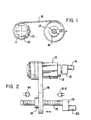
- Figs. 1 and 4 a mandrel 10 having an octagonal shaped outer surface configuration and a cylindrical inner bore 11 that is received by a shaft 12.
- Shaft 12 as schematically shown in Figs. 1 and 2, is suitably supported for rotation through the output of a transmission means 13 powered by a variable speed motor 14.
- a supply spool 16 Mounted on a threaded shaft 15 which is parallel to the axis of shaft 12 is a supply spool 16 having a ribbon of an elastomer or rubber 18 wound thereon.
- the speed of rotation of shaft 15 is controlled by a transmission means 19 which in turn is controlled by a variable speed motor 20.
- the reciprocating movement of supply spool 16 is controlled by adjustable limit switches S-1 and S-2. As seen in Figs. 1 and 2, a single thickness of rubber ribbon 18 is wound onto mandrel 10 to form the uncured bearing surface of the bearing assembly.
- the elastomeric material of which the ribbon 18 is made in a suitable natural, synthetic rubber or a rubber having a combination of these materials that can be vulcanized to exhibit a low coefficient of friction when lubricated with water.
- the elastomeric material should have adequate resiliency, strength and sufficient heat resistance to assure a universal application as a bearing assembly.
- acceptable elastomers for use as a ribbon is conventional nitrile rubber compositions, particularly rubber compositions comprising polymers of butadiene and acrylonitrile where butadiene is the major component of the polymer. Neoprene, nitrile, hypalon, Viton, SBR or any of the general family of elastomeric materials may be used. Natural and other synthetic rubber compositions are available for such use, having the properties discussed above.
- a single wide piece of rubber may be wound onto the mandrel.
- the respective ends of the ribbon of rubber on mandrel 10 are wrapped with a sealing tape 21 wherein the tape .21 extends over onto mandrel 10 to protect such mandrel from cement and the epoxy resin that is to be applied to the fiberglass as to be described.
- a thin layer or film of a rubber bonding cement 23 is then sprayed, brushed or rolled onto the exterior surface of the uncured rubber ribbon 18 on mandrel 10.
- a thin layer or layers of glass fabric sheets or ribbon is then wound onto the layer of cement 23 such as to impregnate the fabric with such cement to assure bonding.
- the number of glass fabric cement impregnated layers applied to the ribbon of rubber is determined by the strength needed. In some instances it may be desirable to coat the second or subsequent layers of glass fabric with the cement prior to their application to the first layer that is in contact with the bonding cement 23 to assure a complete bonding.
- mandrel 10 with the ribbon of rubber 18 and the film of bonding cement 23 is placed on a support or shaft 25 for rotation (Fig. 3).
- Shaft 25 is suitably rotated by means not shown but old and well known in the art.
- a woven fabric of fiberglass 30 is then wound onto the outer periphery of the bearing assembly being formed on mandrel 10 to first contact the cement and, as stated earlier, such initial layers are cement impregnated. Thereafter as the fiberglass 30 is wound thereon, the fabric is coated with an epoxy resin from a reservoir 31 with the aid of a doctor blade.
- the epoxy resin can be applied manually or by any knwon mechanical means.
- the number of layers of impregnated fiberglass fabric 30 that are wound around the mandrel 10 is determined by the desired size needed.
- a specific example of the epoxy resin useful in the present invention is one by the trade name "APCO” available from Applied Plastics Co., Inc. of EI Segundo, California.
- the epoxy resin has a specific gravity of 1.165 and its accompanying hardener has a specific gravity of 1.809.
- the epoxy resin has a Shore D 25°C hardness of 84 with a glass transition temperature of 196°F.
- Another epoxy resin that can be used is "Everfix Epoxy Resin” having a density of 8.5lbs. per gallon.
- the hardener used with such epoxy resin is a modified aliphatic amine adduct available through Fiber Glass-Evercoat Co., Inc., 6600 Cor- nell Road, Cincinnati, Ohio.
- the fiberglass fabric 30 is supplied from a storage roll 35 supported on an axle or shaft 36 driven in synchronism with shaft 25.
- a brake mechanism 38 is cooperative with shaft 36 to facilitate the winding operation.
- the bearing assembly on completing the winding of the fiberglass is then slowly rotated until the epoxy resin has gelled and set. Additional time is then given to the epoxy resin to harden to form a rigid outer plastic shell 40. This can be accomplished by continuing the rotation of the bearing assembly in the mandrel or to set aside the bearing assembly until the epoxy had hardened. Thereafter the elastomeric material or rubber ribbon is cured into a sleeve as by placing the entire bearing assembly into a hot air oven, a steam autoclave or liquid curing bath. In such instance, the rigid fiberglass-epoxy or plastic outer shell 40 becomes a mold to contain the rubber 18 and the layer of cement 23 thereby resisting the curing pressures as the rubber 18 expands and vulcanizes.
- An alternative method of curing the layer of rubber 18 is to retain the uncurred bearing assembly on the hollow mandrel 10 and to remove it from the support or shaft 25 and thence after the epoxy has hardened to introduce steam or hot air into bore 11 of mandrel 10 to effect vulcanization of the rubber 18.
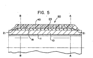
- Another method to effect vulcanization of the rubber 18 is to utilize CALROD type heating mandrels or inserts within the bore 11 of mandrel 10. By such vulcanization process the rubber is cured and the rubber cement layer 23 adheres to the fiberglass layer or layers and to the fiberglass impregnated with the epoxy to form a unitary integral bearing assembly 50.
- the housing assembly 50 is removed from the curing environment or apparatus used, such as the autoclave, and allowed to cool. As the bearing assembly 50 cools, the mandrel 10 shrinks decreasing its outside diameter while simultaneously therewith the layer of rubber 18 shrinks decreasing its inside diameter while retaining its bond to the rigid plastic outer shell 40. This combined action frees the bearing assembly 50 ' from the mandrel 10 and facilitates the withdrawal of the mandrel 10 from the bearing assembly 50. Thereafter the bearing assembly 50 is machined along lines A-A and B-B (Fig. 5) to a finished specified length as well as machined to a specified outside diameter.
Landscapes
- Engineering & Computer Science (AREA)
- General Engineering & Computer Science (AREA)
- Mechanical Engineering (AREA)
- Moulding By Coating Moulds (AREA)
- Sliding-Contact Bearings (AREA)
Claims (9)
Applications Claiming Priority (2)
| Application Number | Priority Date | Filing Date | Title |
|---|---|---|---|
| US06/803,441 US4718959A (en) | 1985-12-02 | 1985-12-02 | Method of making a bearing assembly |
| US803441 | 1985-12-02 |
Publications (3)
| Publication Number | Publication Date |
|---|---|
| EP0225569A2 EP0225569A2 (fr) | 1987-06-16 |
| EP0225569A3 EP0225569A3 (en) | 1987-08-05 |
| EP0225569B1 true EP0225569B1 (fr) | 1990-01-31 |
Family
ID=25186511
Family Applications (1)
| Application Number | Title | Priority Date | Filing Date |
|---|---|---|---|
| EP86116620A Expired - Lifetime EP0225569B1 (fr) | 1985-12-02 | 1986-11-29 | Procédé de fabrication d'un palier |
Country Status (5)
| Country | Link |
|---|---|
| US (1) | US4718959A (fr) |
| EP (1) | EP0225569B1 (fr) |
| JP (1) | JPS62146617A (fr) |
| DE (1) | DE3668580D1 (fr) |
| MX (1) | MX160974A (fr) |
Families Citing this family (9)
| Publication number | Priority date | Publication date | Assignee | Title |
|---|---|---|---|---|
| FR2675072B1 (fr) * | 1991-04-15 | 1994-11-25 | Europ Propulsion | Procede de fabrication de butees lamifiees notamment pour articulations de tuyeres de propulseurs. |
| DE4430037C2 (de) * | 1994-08-24 | 1996-12-12 | Metzeler Gimetall Ag | Lagerbuchse |
| WO2013060966A1 (fr) * | 2011-10-26 | 2013-05-02 | Snecma | Mandrin d'impregnation a bache vide pour la fabrication d'un carter de turbine a gaz en materiau composite |
| US9452562B2 (en) * | 2011-10-26 | 2016-09-27 | Snecma | Impregnation clamping mandrel for making gas turbine casings made of composite material |
| CN102720758A (zh) * | 2012-05-30 | 2012-10-10 | 中国科学院长春应用化学研究所 | 一种复合材料背衬水润滑橡胶轴承及其制备方法 |
| CN102825814B (zh) * | 2012-09-05 | 2015-04-08 | 中国科学院长春应用化学研究所 | 一种以硬质橡胶为内衬水润滑轴承的制造方法 |
| CN104863964B (zh) * | 2015-04-15 | 2017-07-18 | 泉州市德源轴承实业有限公司 | 一种缠绕式滑动轴承的成型方法 |
| CN110806316B (zh) * | 2019-10-11 | 2021-07-13 | 中国人民解放军海军工程大学 | 用于水润滑轴承受力状态检测的光纤光栅传感装置及其监测系统 |
| RU2726348C1 (ru) * | 2019-10-16 | 2020-07-13 | ФЕДЕРАЛЬНОЕ ГОСУДАРСТВЕННОЕ БЮДЖЕТНОЕ ОБРАЗОВАТЕЛЬНОЕ УЧРЕЖДЕНИЕ ВЫСШЕГО ОБРАЗОВАНИЯ "Брянский государственный технический университет" | Подшипник скольжения |
Family Cites Families (8)
| Publication number | Priority date | Publication date | Assignee | Title |
|---|---|---|---|---|
| US2589786A (en) * | 1945-04-10 | 1952-03-18 | Glenn L Martin Co | Method of forming hollow plastic bodies |
| US3507023A (en) * | 1968-05-02 | 1970-04-21 | Textron Inc | Plastic-impregnated fabric journal bearing |
| GB1477650A (en) * | 1974-11-29 | 1977-06-22 | Pneumatiques Caoutchouc Mfg | Strips for use in or as transmission belts |
| US4331496A (en) * | 1980-03-10 | 1982-05-25 | The B. F. Goodrich Company | Bearing assembly and method for making same |
| US4344806A (en) * | 1981-03-23 | 1982-08-17 | The B. F. Goodrich Company | Method of making a bearing |
| US4596619A (en) * | 1982-05-17 | 1986-06-24 | Hercules Incorporated | Process for lining composite vessels |
| US4570315A (en) * | 1983-03-07 | 1986-02-18 | The B. F. Goodrich Company | Method of making a bearing |
| US4512836A (en) * | 1983-08-22 | 1985-04-23 | Mcdonnell Douglas Corporation | Method of producing composite structural members |
-
1985
- 1985-12-02 US US06/803,441 patent/US4718959A/en not_active Expired - Fee Related
-
1986
- 1986-11-29 DE DE8686116620T patent/DE3668580D1/de not_active Expired - Fee Related
- 1986-11-29 EP EP86116620A patent/EP0225569B1/fr not_active Expired - Lifetime
- 1986-12-01 MX MX4487A patent/MX160974A/es unknown
- 1986-12-02 JP JP61286120A patent/JPS62146617A/ja active Pending
Also Published As
| Publication number | Publication date |
|---|---|
| JPS62146617A (ja) | 1987-06-30 |
| DE3668580D1 (de) | 1990-03-08 |
| EP0225569A2 (fr) | 1987-06-16 |
| US4718959A (en) | 1988-01-12 |
| MX160974A (es) | 1990-06-29 |
| EP0225569A3 (en) | 1987-08-05 |
Similar Documents
| Publication | Publication Date | Title |
|---|---|---|
| EP0035782B1 (fr) | Assemblage de palier et procédé pour sa fabrication | |
| US4368568A (en) | Elastomeric material covered rolls and a method of making the same | |
| US7285177B2 (en) | Thin-walled reinforced sleeve with integral compressible layer | |
| CA2173534C (fr) | Cylindre revetu et methode de fabrication correspondante | |
| CA1250878A (fr) | Palier | |
| US4718959A (en) | Method of making a bearing assembly | |
| CA1231362A (fr) | Palier | |
| US4570315A (en) | Method of making a bearing | |
| US4577379A (en) | Bearing assembly and method for assembling a bearing | |
| US4677721A (en) | Method for fabricating an elastomeric bearing assembly | |
| US3697348A (en) | Method of making gaskets | |
| US4344806A (en) | Method of making a bearing | |
| CA1256150A (fr) | Ensemble porteur | |
| US4663810A (en) | Method for fabricating an elastomeric bearing assembly | |
| US4256523A (en) | Method for the manufacture of a pipe | |
| US5248361A (en) | Method of manufacturing laminated flexible bearings, in particular for engine nozzle joints | |
| CN1532333A (zh) | 带有用于改善强度和粘接性能的树脂浸渍密集纤维内衬层的包覆辊 | |
| US2932856A (en) | Method for manufacturing roller assemblies | |
| JPH0214895B2 (fr) | ||
| JP2987342B2 (ja) | 釣竿の製造方法 | |
| JP2002081436A (ja) | ゴムロールの製造方法 | |
| JPS5824432A (ja) | 耳付きゴム弾性管の製造方法 | |
| JPH05269867A (ja) | 繊維強化樹脂製成形品の製造方法 | |
| JPH0132770B2 (fr) |
Legal Events
| Date | Code | Title | Description |
|---|---|---|---|
| PUAI | Public reference made under article 153(3) epc to a published international application that has entered the european phase |
Free format text: ORIGINAL CODE: 0009012 |
|
| AK | Designated contracting states |
Kind code of ref document: A2 Designated state(s): DE FR GB SE |
|
| PUAL | Search report despatched |
Free format text: ORIGINAL CODE: 0009013 |
|
| AK | Designated contracting states |
Kind code of ref document: A3 Designated state(s): DE FR GB SE |
|
| 17P | Request for examination filed |
Effective date: 19880130 |
|
| 17Q | First examination report despatched |
Effective date: 19881121 |
|
| RAP1 | Party data changed (applicant data changed or rights of an application transferred) |
Owner name: THE B.F. GOODRICH COMPANY |
|
| GRAA | (expected) grant |
Free format text: ORIGINAL CODE: 0009210 |
|
| AK | Designated contracting states |
Kind code of ref document: B1 Designated state(s): DE FR GB SE |
|
| REF | Corresponds to: |
Ref document number: 3668580 Country of ref document: DE Date of ref document: 19900308 |
|
| ET | Fr: translation filed | ||
| PGFP | Annual fee paid to national office [announced via postgrant information from national office to epo] |
Ref country code: FR Payment date: 19901023 Year of fee payment: 5 |
|
| PLBE | No opposition filed within time limit |
Free format text: ORIGINAL CODE: 0009261 |
|
| STAA | Information on the status of an ep patent application or granted ep patent |
Free format text: STATUS: NO OPPOSITION FILED WITHIN TIME LIMIT |
|
| PG25 | Lapsed in a contracting state [announced via postgrant information from national office to epo] |
Ref country code: GB Effective date: 19901129 |
|
| PG25 | Lapsed in a contracting state [announced via postgrant information from national office to epo] |
Ref country code: SE Effective date: 19901130 |
|
| 26N | No opposition filed | ||
| GBPC | Gb: european patent ceased through non-payment of renewal fee | ||
| PG25 | Lapsed in a contracting state [announced via postgrant information from national office to epo] |
Ref country code: DE Effective date: 19910801 |
|
| PG25 | Lapsed in a contracting state [announced via postgrant information from national office to epo] |
Ref country code: FR Effective date: 19920731 |
|
| REG | Reference to a national code |
Ref country code: FR Ref legal event code: ST |
|
| EUG | Se: european patent has lapsed |
Ref document number: 86116620.5 Effective date: 19910705 |