EP0225620B1 - Dispositif d'admission pour moteur à combustion interne à plusieurs cylindres - Google Patents
Dispositif d'admission pour moteur à combustion interne à plusieurs cylindres Download PDFInfo
- Publication number
- EP0225620B1 EP0225620B1 EP86116966A EP86116966A EP0225620B1 EP 0225620 B1 EP0225620 B1 EP 0225620B1 EP 86116966 A EP86116966 A EP 86116966A EP 86116966 A EP86116966 A EP 86116966A EP 0225620 B1 EP0225620 B1 EP 0225620B1
- Authority
- EP
- European Patent Office
- Prior art keywords
- resonance
- combustion engine
- internal combustion
- collector
- tubes
- Prior art date
- Legal status (The legal status is an assumption and is not a legal conclusion. Google has not performed a legal analysis and makes no representation as to the accuracy of the status listed.)
- Expired
Links
- 238000002485 combustion reaction Methods 0.000 title claims description 80
- 238000010276 construction Methods 0.000 claims description 3
- 238000011144 upstream manufacturing Methods 0.000 claims description 3
- 230000008859 change Effects 0.000 claims description 2
- 238000005192 partition Methods 0.000 claims description 2
- 239000003570 air Substances 0.000 description 50
- 230000002349 favourable effect Effects 0.000 description 5
- 230000000694 effects Effects 0.000 description 4
- 230000010355 oscillation Effects 0.000 description 4
- 230000005284 excitation Effects 0.000 description 2
- 230000003584 silencer Effects 0.000 description 2
- 239000007787 solid Substances 0.000 description 2
- 239000012080 ambient air Substances 0.000 description 1
- 230000015572 biosynthetic process Effects 0.000 description 1
- 230000015556 catabolic process Effects 0.000 description 1
- 238000013016 damping Methods 0.000 description 1
- 230000001419 dependent effect Effects 0.000 description 1
- 238000010586 diagram Methods 0.000 description 1
- 238000006073 displacement reaction Methods 0.000 description 1
- 238000002347 injection Methods 0.000 description 1
- 239000007924 injection Substances 0.000 description 1
- 230000003993 interaction Effects 0.000 description 1
- 238000000034 method Methods 0.000 description 1
- 230000008569 process Effects 0.000 description 1
- 238000010926 purge Methods 0.000 description 1
- 230000009467 reduction Effects 0.000 description 1
- 238000004904 shortening Methods 0.000 description 1
- 230000007704 transition Effects 0.000 description 1
- 230000001960 triggered effect Effects 0.000 description 1
- 230000003313 weakening effect Effects 0.000 description 1
Images



Classifications
-
- F—MECHANICAL ENGINEERING; LIGHTING; HEATING; WEAPONS; BLASTING
- F02—COMBUSTION ENGINES; HOT-GAS OR COMBUSTION-PRODUCT ENGINE PLANTS
- F02B—INTERNAL-COMBUSTION PISTON ENGINES; COMBUSTION ENGINES IN GENERAL
- F02B27/00—Use of kinetic or wave energy of charge in induction systems, or of combustion residues in exhaust systems, for improving quantity of charge or for increasing removal of combustion residues
- F02B27/02—Use of kinetic or wave energy of charge in induction systems, or of combustion residues in exhaust systems, for improving quantity of charge or for increasing removal of combustion residues the systems having variable, i.e. adjustable, cross-sectional areas, chambers of variable volume, or like variable means
- F02B27/0226—Use of kinetic or wave energy of charge in induction systems, or of combustion residues in exhaust systems, for improving quantity of charge or for increasing removal of combustion residues the systems having variable, i.e. adjustable, cross-sectional areas, chambers of variable volume, or like variable means characterised by the means generating the charging effect
- F02B27/0247—Plenum chambers; Resonance chambers or resonance pipes
- F02B27/0252—Multiple plenum chambers or plenum chambers having inner separation walls, e.g. comprising valves for the same group of cylinders
-
- F—MECHANICAL ENGINEERING; LIGHTING; HEATING; WEAPONS; BLASTING
- F02—COMBUSTION ENGINES; HOT-GAS OR COMBUSTION-PRODUCT ENGINE PLANTS
- F02B—INTERNAL-COMBUSTION PISTON ENGINES; COMBUSTION ENGINES IN GENERAL
- F02B27/00—Use of kinetic or wave energy of charge in induction systems, or of combustion residues in exhaust systems, for improving quantity of charge or for increasing removal of combustion residues
- F02B27/02—Use of kinetic or wave energy of charge in induction systems, or of combustion residues in exhaust systems, for improving quantity of charge or for increasing removal of combustion residues the systems having variable, i.e. adjustable, cross-sectional areas, chambers of variable volume, or like variable means
- F02B27/0205—Use of kinetic or wave energy of charge in induction systems, or of combustion residues in exhaust systems, for improving quantity of charge or for increasing removal of combustion residues the systems having variable, i.e. adjustable, cross-sectional areas, chambers of variable volume, or like variable means characterised by the charging effect
- F02B27/021—Resonance charging
-
- F—MECHANICAL ENGINEERING; LIGHTING; HEATING; WEAPONS; BLASTING
- F02—COMBUSTION ENGINES; HOT-GAS OR COMBUSTION-PRODUCT ENGINE PLANTS
- F02B—INTERNAL-COMBUSTION PISTON ENGINES; COMBUSTION ENGINES IN GENERAL
- F02B27/00—Use of kinetic or wave energy of charge in induction systems, or of combustion residues in exhaust systems, for improving quantity of charge or for increasing removal of combustion residues
- F02B27/02—Use of kinetic or wave energy of charge in induction systems, or of combustion residues in exhaust systems, for improving quantity of charge or for increasing removal of combustion residues the systems having variable, i.e. adjustable, cross-sectional areas, chambers of variable volume, or like variable means
- F02B27/0205—Use of kinetic or wave energy of charge in induction systems, or of combustion residues in exhaust systems, for improving quantity of charge or for increasing removal of combustion residues the systems having variable, i.e. adjustable, cross-sectional areas, chambers of variable volume, or like variable means characterised by the charging effect
- F02B27/0215—Oscillating pipe charging, i.e. variable intake pipe length charging
- F02B27/0221—Resonance charging combined with oscillating pipe charging
-
- F—MECHANICAL ENGINEERING; LIGHTING; HEATING; WEAPONS; BLASTING
- F02—COMBUSTION ENGINES; HOT-GAS OR COMBUSTION-PRODUCT ENGINE PLANTS
- F02B—INTERNAL-COMBUSTION PISTON ENGINES; COMBUSTION ENGINES IN GENERAL
- F02B27/00—Use of kinetic or wave energy of charge in induction systems, or of combustion residues in exhaust systems, for improving quantity of charge or for increasing removal of combustion residues
- F02B27/02—Use of kinetic or wave energy of charge in induction systems, or of combustion residues in exhaust systems, for improving quantity of charge or for increasing removal of combustion residues the systems having variable, i.e. adjustable, cross-sectional areas, chambers of variable volume, or like variable means
- F02B27/0226—Use of kinetic or wave energy of charge in induction systems, or of combustion residues in exhaust systems, for improving quantity of charge or for increasing removal of combustion residues the systems having variable, i.e. adjustable, cross-sectional areas, chambers of variable volume, or like variable means characterised by the means generating the charging effect
- F02B27/0268—Valves
- F02B27/0273—Flap valves
-
- F—MECHANICAL ENGINEERING; LIGHTING; HEATING; WEAPONS; BLASTING
- F02—COMBUSTION ENGINES; HOT-GAS OR COMBUSTION-PRODUCT ENGINE PLANTS
- F02B—INTERNAL-COMBUSTION PISTON ENGINES; COMBUSTION ENGINES IN GENERAL
- F02B27/00—Use of kinetic or wave energy of charge in induction systems, or of combustion residues in exhaust systems, for improving quantity of charge or for increasing removal of combustion residues
- F02B27/02—Use of kinetic or wave energy of charge in induction systems, or of combustion residues in exhaust systems, for improving quantity of charge or for increasing removal of combustion residues the systems having variable, i.e. adjustable, cross-sectional areas, chambers of variable volume, or like variable means
- F02B27/0226—Use of kinetic or wave energy of charge in induction systems, or of combustion residues in exhaust systems, for improving quantity of charge or for increasing removal of combustion residues the systems having variable, i.e. adjustable, cross-sectional areas, chambers of variable volume, or like variable means characterised by the means generating the charging effect
- F02B27/0289—Intake runners having multiple intake valves per cylinder
-
- F—MECHANICAL ENGINEERING; LIGHTING; HEATING; WEAPONS; BLASTING
- F02—COMBUSTION ENGINES; HOT-GAS OR COMBUSTION-PRODUCT ENGINE PLANTS
- F02B—INTERNAL-COMBUSTION PISTON ENGINES; COMBUSTION ENGINES IN GENERAL
- F02B75/00—Other engines
- F02B75/16—Engines characterised by number of cylinders, e.g. single-cylinder engines
- F02B75/18—Multi-cylinder engines
- F02B2075/1804—Number of cylinders
- F02B2075/1824—Number of cylinders six
-
- Y—GENERAL TAGGING OF NEW TECHNOLOGICAL DEVELOPMENTS; GENERAL TAGGING OF CROSS-SECTIONAL TECHNOLOGIES SPANNING OVER SEVERAL SECTIONS OF THE IPC; TECHNICAL SUBJECTS COVERED BY FORMER USPC CROSS-REFERENCE ART COLLECTIONS [XRACs] AND DIGESTS
- Y02—TECHNOLOGIES OR APPLICATIONS FOR MITIGATION OR ADAPTATION AGAINST CLIMATE CHANGE
- Y02T—CLIMATE CHANGE MITIGATION TECHNOLOGIES RELATED TO TRANSPORTATION
- Y02T10/00—Road transport of goods or passengers
- Y02T10/10—Internal combustion engine [ICE] based vehicles
- Y02T10/12—Improving ICE efficiencies
Definitions
- the invention is based on the preamble of the independent claim from JP-A 59/82523.
- the intake system As a resonance system with resonance tubes and resonance containers.
- the resonance containers are connected via suction lines to groups of combustion chambers with the same ignition or injection intervals, as is shown and described, for example, in DE-C 1 935 155 for a 6-cylinder internal combustion engine equipped with an exhaust gas turbocharger.
- an intake system for a multi-cylinder internal combustion engine is known from JP-A 56 115 818, in which an oscillating tube system is combined with a resonance system.
- the collector provided for the vibrating tube system is divided into two volumes by means of a controllable throttle valve, which serve as a resonance volume or as a resonance container.
- the vibrating tube system combined with a resonance system has only one suction line to each combustion chamber of the multi-cylinder internal combustion engine.
- Systems of this type show a first favorable curve profile for the air expenditure in a transition area from lower to medium speeds and also a second favorable curve profile for the air expenditure in the upper speed range.
- the invention is therefore based on the object of developing a multi-cylinder internal combustion engine in such a way that the air expenditure is improved from the lower to the upper operating range.
- the basic idea of the invention is to generate different resonances in the resonance system in a multi-cylinder internal combustion engine with an intake system combined from a vibrating tube system and a resonance system by means of several vibrating tubes which can be switched on and / or off depending on the operating point and are provided for each combustion chamber or cylinder.
- adjacent resonance ranges are advantageously achieved in terms of speed. This extends the effective range of the resonance system from a relatively narrow speed range to a much larger speed range.
- the two resonance containers are short-circuited, i.e. the two resonance volumes are combined to form the collector volume.
- the influence on the combined intake system in the case of exclusively vibrating pipe operation can be minimized in such a way that a vibrating pipe charge subsequent to the resonance charging is achieved with only first vibrating pipes of the combustion chambers or cylinders, a flat course of the air expenditure curve close to "1".
- Relatively long vibrating tubes of relatively small cross-section are preferably preferred for this vibrating tube supercharging in the middle speed range of the internal combustion engine. This is the one in St.d.T. Typical slump between resonance charging in the lower speed range and vibrating tube charging in the upper speed range avoided.
- At least one further second oscillating tube of at least a relatively large cross section is connected for each combustion chamber or cylinder.
- Switching on the second vibrating tubes means a changed vibration behavior for all openly controlled vibrating tubes due to the relatively shorter vibrating tubes compared to the long vibrating tubes, as the latter is known per se for high speeds.
- the enlarged effective resonance cross section results in a shift in the resonance frequency to higher speeds, which further improves the air consumption in the second half of the lower speed range towards the lower middle speed range.
- the further course of the air expenditure curve for the middle and upper speed range is again essentially effected via the oscillating tubes and its characteristics are essentially identical to the curve course of the embodiment according to claims 1 and 2.
- a preferred embodiment with regard to the construction with respect to the others Embodiment of the invention is described in more detail in claims 5 and 6.
- the short-circuiting of the resonance tank described in claim 6 via intake manifold connected to the expansion tank, together with the weakening of the resonance vibration with increasing engine speed, causes the resonance frequency to be shifted outside the desired speed range.
- the fresh air drawn in flows to the large via the short and preferably large-diameter intake ports, so that the resonance pipes are shunted and, controlled or not controlled, have no influence on the vibration behavior of the vibrating pipes.
- a multi-cylinder internal combustion engine with an intake system according to the invention additionally has a gas exchange control device with an intersection of inlet and outlet.
- the overlap can be used to flush the combustion chamber.
- the gas exchange control device preferably for exhaust valves has a separate control shaft with a control shaft adjusting device for changing the phase position of the control shaft relative to the crankshaft, then the extent of the overlap can be changed on the outlet side depending on the operating point, in particular depending on the speed.
- the multi-cylinder internal combustion engine with the intake system according to the invention and / or the above-described gas exchange control device can additionally be equipped with a charger.
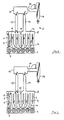
- a 6-cylinder in-line internal combustion engine 1 is equipped with an intake system 2, which is formed from a vibrating tube system 3 and a resonance system 4.
- an intake system 2 which is formed from a vibrating tube system 3 and a resonance system 4.
- two oscillating tubes 6 and 7 are assigned to each combustion chamber 5 of the internal combustion engine 1.
- the first and second vibrating tubes 6 and 7 are connected to a collector 8 at the end remote from the engine.
- the second vibrating tubes 7 are of relatively large diameter and relatively short.
- the first vibrating tubes 6, are of relatively small diameter and relatively long length, which is preferably achieved by an arcuate course between the respective combustion chamber 5 and the collector 8.
- a shut-off element 9 is arranged near the combustion chamber.
- the collector 8 can be divided by a shut-off device 10 into two resonance containers 11 and 12 of the same volume.
- the two resonance tanks 11 and 12 are each connected to three combustion chambers 5 of the internal combustion engine 1 via the first and second oscillating tubes 6 and 7, with a suction sequence of 240 ° KW being given in each group of the three combustion chambers 5.
- Tubes 13 and 14 connected, which serve as resonance tubes when the collector 8 is divided into the resonance containers 11 and 12.
- the resonance tubes 13 and 14 cooperate with an expansion tank 15, which is formed with an independently controlled air inlet 16.
- An air flow meter 17 and an intake silencer 18 are arranged upstream of the air inlet 16.
- the collector shut-off device 10 and the oscillating pipe shut-off devices 9 are controlled relative to the independently controlled air inlet 16 either in the same direction or alternately in opposite directions by means of a computer, depending on the operating point. With appropriate control of the aforementioned shut-off devices, an improved resonance charging in the lower speed range of the internal combustion engine 1 is thus achieved.
- the improved resonance charging is shown in FIG. 9 on the basis of the solid curve for the air expenditure, the dotted curve corresponding to the air expenditure of an intake system formed in a conventional manner from a vibrating tube system and a resonance system.
- the solid curve representing the course of the air expenditure over the entire speed range of the internal combustion engine 1 at full load comprises first curve sections A and B, which are achieved by resonance charging.
- the natural frequency of the resonance containers 11 and 12 and the resonance tubes 13 and 14 connected to them is tuned for the lowest speed range of the internal combustion engine 1.
- the resonance containers 11 and 12 each have a defined volume, the resonance tubes 13 and 14 each having a specific length and a specific diameter.
- the second, short vibrating pipes 7 are closed by the shut-off elements 9.
- the resonance oscillation propagates to the respective combustion chamber 5 only via the first longer oscillating tube 6 with a small cross section.
- Each vibrating tube 6 is designed in terms of its length and its cross section with a view to a relatively small volume in order to dampen the resonance vibration as little as possible.
- the shut-off elements 9 of the second short oscillating tubes 7 are additionally opened according to FIG. 2.
- the fresh air drawn in thus flows to the respective combustion chamber 5 via a considerably enlarged cross-section of the oscillating tube.
- Switching on the second vibrating tubes 7 causes the resonance to be shifted to higher speeds of the internal combustion engine 1.
- Corresponding tuning of the vibrating tubes in their geometrical dimensions results in a curved portion B following the curved portion A without significant breakdown.
- the resonance vibration weakens.
- the two resonance containers 11 and 12 are connected to one another by opening the shut-off element 10 according to FIG. 3.
- the vibrating tube shut-off elements 9 are moved in opposite directions relative to the collector shut-off element 10 in order to close the second, short vibrating tubes 7.
- the fresh air therefore flows to each combustion chamber 5 exclusively via the first, relatively long oscillating tube 6 of relatively small cross-section.
- the relatively small pipe cross-section causes a high flow rate.
- a certain reloading effect is brought about with the relatively long oscillating tubes 6 towards the inlet end.
- the length of the vibrating tubes 6 is of further importance for high air expenditure in the medium speed range. Since the length and diameter of the vibrating tubes 6 is also important for the speed range corresponding to curve A with resonance charging; A compromise must be found with regard to the respective length of the vibrating tubes 6, which results in a high air expenditure both in the lower speed range corresponding to the curve section and in the middle speed range corresponding to curve section A.
- Each suction process triggered in a combustion chamber 5 causes a suction wave migrating against the incoming fresh air in the connected, open oscillating tube 6 or 7.
- Such a suction wave triggers such a natural vibration in the lower speed range in the resonance system 4 switched according to FIGS. 1 and 2 that a resonance pressure wave is present at the open inlet.
- the diameter of the relatively long vibrating tubes 6 is particularly important for this.
- the suction wave reflected at the open tube end is applied as a pressure wave at the open inlet and thus acts to promote filling.
- the second, short oscillation tubes 7 are connected to the first, long oscillation tubes 6 by opening the shut-off elements 9.
- the 6-cylinder in-line internal combustion engine 19 with combustion chambers 20 shown in FIG. 5 with 8 is included 1 with 4 modified intake system 21 compared to the internal combustion engine 1 of FIG. 1, by means of which the air expenditure and thus the combustion chamber filling can be increased further in the lower speed range, as shown by the dashed curve in FIG. 9.
- Each combustion chamber 20 of the internal combustion engine 19 is connected to two oscillating tubes 22 and 23.
- Each first oscillating tube 22 is of an arcuate shape of relatively great length (not shown in the drawing) and has a relatively small cross section.
- every second vibrating tube 23 is relatively short and has a relatively large cross section.
- a shut-off device 24 is assigned to each short oscillating tube 23 near the combustion chamber.
- the first, long oscillating tubes 22 are connected to a collector 25.
- a collector 25 Structurally adjacent to the collector 25 is an expansion tank 26 with which the second, short oscillating tubes 23 are connected in an air-guiding manner.
- the expansion tank 26 has an independently controllable air inlet 27 which is connected upstream to an air quantity or air mass meter 28 and an intake silencer 29.
- the collector 25 divides a partition 30 into the resonance containers 31 and 32. Furthermore, the collector 25 in the region of each resonance container 31 and 32 each has an intake port 33 and 34 connected to the compensating container 26. Each of the intake ports 33, 34 is equipped with a shut-off device 35.
- the resonance tanks 31 and 32 are each connected to the expansion tank 26 via a long resonance tube 36 and a short resonance tube 37.
- the short resonance pipes 37 are each equipped with a shut-off device 38 at the confluence with the resonance containers 31 and 32.
- the cross section of the resonance pipes 13, 14 is in each case in smaller cross sections for several Resonance tubes 36, 37 divided into a resonance container 31, 32.
- the resonance tubes 36 and 37 are of different lengths, the relatively shorter resonance tubes 37 being closable in a controlled manner by the shut-off device 38 depending on the operating point.
- a cross section is sought in addition to a relatively large length, which is approximately the cross section of the first, long one Vibration tubes 22 corresponds.
- This large pipe length with a relatively small cross section brings about a considerable increase in the air expenditure at the lowest speeds, as is shown by the curve section A 'in FIG. 9. 5, the shut-off elements 35 in the intake ports 33, 34, the shut-off elements 38 in the short resonance tubes 37 and finally the shut-off elements 24 of the second short oscillating tubes 23 are brought under computer control into the closed position.
- the shut-off elements 38 are brought into the open position in the short resonance tubes 37. This increases the effective resonance tube cross section. Due to the different lengths of the resonance tubes 36 and 37, in conjunction with the enlarged effective resonance cross section, there is a shift in the resonance frequency to higher speeds according to the curve section B 'in FIG. 9. As can be seen from FIG. 6, the shut-off elements 35 are in this resonance charge the intake manifold 33 and 34 and the shut-off devices 24 of the short swing pipes in the closed position.
- the resonance oscillation weakens and the intake system 21 is therefore switched over from the resonance charging to the oscillating tube charging.
- the shut-off devices 35 in the intake ports 33 and 34 are brought into the open position.
- the resonance tanks 31 and 32, which each form one half of the collector 25, are thus short-circuited via the structurally adjacent expansion tank 26, whereby the collector 25 assumes its function in the oscillating tube system 40 due to the excitation frequency reduced from 240 ° KW to 120 ° KW.
- the fresh air is therefore largely supplied to the combustion chambers 20 of the internal combustion engine 19 via the open intake ports 33 and 34, the collector 25 and the first, long oscillating tubes 22.
- the second, short oscillating tubes 23 are switched on by opening the shut-off elements 24.
- shorter vibrating tubes are achieved in their effective length with the effect of a displacement of the vibrating tube charging to higher speeds.
- the corresponding course of the air expenditure therefore again essentially corresponds to the curve section D in FIG. 9.
- the air expenditure can also be further improved in resonance mode if internal combustion engines 1 and 19 are each equipped with a gas exchange control device which has or enables an overlap of inlet and outlet.
- a gas exchange control device which has or enables an overlap of inlet and outlet.
- the resonance pressure wave present at the open inlet can purge the combustion chamber via the just open outlet and then with the outlet closed lead to an increase in the load.
- the increase in the cylinder charge is additionally caused by reduced backflow losses before the intake closure between the UT and the intake control.
- Such a gas exchange control causes an internal combustion engine 1 or 19 to shift the curve pieces A and B 'in the direction of the air expenditure value "1".
- each of the internal combustion engines designed according to the invention can be equipped with a charger.
- any internal combustion engine equipped according to the invention can also suck in freely from the ambient air via the resonance pipes, a resonance pipe of each resonance system then simultaneously forming an independently controlled air inlet.
Landscapes
- Engineering & Computer Science (AREA)
- Chemical & Material Sciences (AREA)
- Combustion & Propulsion (AREA)
- Mechanical Engineering (AREA)
- General Engineering & Computer Science (AREA)
- Characterised By The Charging Evacuation (AREA)
Claims (9)
Applications Claiming Priority (2)
| Application Number | Priority Date | Filing Date | Title |
|---|---|---|---|
| DE19853544122 DE3544122A1 (de) | 1985-12-13 | 1985-12-13 | Mehrzylinder-brennkraftmaschine mit ansauganlage |
| DE3544122 | 1985-12-13 |
Publications (3)
| Publication Number | Publication Date |
|---|---|
| EP0225620A2 EP0225620A2 (fr) | 1987-06-16 |
| EP0225620A3 EP0225620A3 (en) | 1988-04-20 |
| EP0225620B1 true EP0225620B1 (fr) | 1989-10-04 |
Family
ID=6288376
Family Applications (1)
| Application Number | Title | Priority Date | Filing Date |
|---|---|---|---|
| EP86116966A Expired EP0225620B1 (fr) | 1985-12-13 | 1986-12-06 | Dispositif d'admission pour moteur à combustion interne à plusieurs cylindres |
Country Status (3)
| Country | Link |
|---|---|
| EP (1) | EP0225620B1 (fr) |
| DE (2) | DE3544122A1 (fr) |
| ES (1) | ES2011243B3 (fr) |
Cited By (1)
| Publication number | Priority date | Publication date | Assignee | Title |
|---|---|---|---|---|
| DE4018612A1 (de) * | 1990-06-11 | 1991-12-12 | Audi Ag | Ansaugsystem fuer eine mehrzylinder-brennkraftmaschine |
Families Citing this family (15)
| Publication number | Priority date | Publication date | Assignee | Title |
|---|---|---|---|---|
| US4756284A (en) * | 1986-01-21 | 1988-07-12 | Mazda Motor Corporation | Intake system for internal combustion engine |
| DE3702827A1 (de) * | 1987-01-30 | 1988-08-11 | Bayerische Motoren Werke Ag | Ansauganlage mit einer steuervorrichtung, insbesondere fuer brennkraftmaschinen |
| HU209183B (en) * | 1988-10-18 | 1994-03-28 | Autoipari Kutato Fejlesztoe | Resomance system of variable geometry for fresh-gas conduit of internal combustion engines |
| DE3909837A1 (de) * | 1989-03-25 | 1990-09-27 | Audi Ag | Saugrohranlage fuer eine mehrzylinder-brennkraftmaschine |
| AT404161B (de) * | 1989-10-16 | 1998-09-25 | Avl Verbrennungskraft Messtech | Ansaugsystem für mehrzylinder-hubkolben- brennkraftmaschinen |
| DE4012558A1 (de) * | 1990-04-20 | 1991-10-24 | Bayerische Motoren Werke Ag | Verfahren zur generierung von frischgasschwingungen in einer ansauganlage fuer brennkraftmaschinen |
| DE4039992A1 (de) * | 1990-12-14 | 1992-06-17 | Daimler Benz Ag | Verfahren zur steuerung der luftzufuhr bei einer brennkraftmaschine |
| GB9103597D0 (en) * | 1991-02-21 | 1991-04-10 | Vickers Plc | Exhaust gas control system |
| DE4431539A1 (de) | 1994-09-03 | 1996-03-07 | Opel Adam Ag | Ansaugsystem für eine mehrzylindrige Brennkraftmaschine |
| DE4435554A1 (de) * | 1994-10-05 | 1996-04-18 | Porsche Ag | Saugrohranlage für eine Brennkraftmaschine mit zwei Reihen von Zylindern |
| DE19531985A1 (de) * | 1995-08-30 | 1997-03-06 | Marco Herr | Ansaugsystem für eine Kolbenbrennkraftmaschine |
| NL1002516C2 (nl) * | 1996-03-04 | 1997-09-05 | Netherlands Car Bv | Verbrandingsmotor. |
| DE19800063B4 (de) * | 1998-01-02 | 2006-04-13 | Volkswagen Ag | Sauganlage zur Verbrennungsluftversorgung einer Brennkraftmaschine und Verfahren zu deren Steuerung |
| EP0980968A1 (fr) * | 1998-08-20 | 2000-02-23 | FILTERWERK MANN + HUMMEL GmbH | Dispositif d'admission pour moteur à combustion interne |
| DE59903052D1 (de) * | 1998-08-20 | 2002-11-14 | Mann & Hummel Filter | Ansaugvorrichtung für eine brennkraftmaschine |
Family Cites Families (8)
| Publication number | Priority date | Publication date | Assignee | Title |
|---|---|---|---|---|
| FR1457282A (fr) * | 1964-12-14 | 1966-01-24 | Inst Francais Du Petrole | Perfectionnements à l'alimentation des moteurs à piston rotatif |
| HU173034B (hu) * | 1975-05-13 | 1979-02-28 | Autoipari Kutato Intezet | Sistema truboprovodov dlja podvoda svezhego gaza k shesticilindrovomu dvigatelju s turbonasosom |
| JPS6014169B2 (ja) * | 1980-01-16 | 1985-04-11 | 日産デイ−ゼル工業株式会社 | 多気筒機関の吸気装置 |
| DE3044292C2 (de) * | 1980-11-25 | 1985-06-20 | Adam Opel AG, 6090 Rüsselsheim | Steuerung eines mehrzylindrigen, fremdgezündeten Einspritz-Verbrennungsmotor |
| JPS5982522A (ja) * | 1982-10-30 | 1984-05-12 | Mazda Motor Corp | エンジンの吸気装置 |
| US4592310A (en) * | 1984-01-26 | 1986-06-03 | Mazda Motor Corporation | Intake device for internal combustion engine |
| JPS60224933A (ja) * | 1984-04-24 | 1985-11-09 | Nissan Motor Co Ltd | 内燃機関の吸気装置 |
| DE3424433A1 (de) * | 1984-07-03 | 1986-01-09 | Dr.Ing.H.C. F. Porsche Ag, 7000 Stuttgart | Luftansauganlage einer mehrzylinder-brennkraftmaschine |
-
1985
- 1985-12-13 DE DE19853544122 patent/DE3544122A1/de not_active Withdrawn
-
1986
- 1986-12-06 EP EP86116966A patent/EP0225620B1/fr not_active Expired
- 1986-12-06 ES ES86116966T patent/ES2011243B3/es not_active Expired - Lifetime
- 1986-12-06 DE DE8686116966T patent/DE3666064D1/de not_active Expired
Cited By (2)
| Publication number | Priority date | Publication date | Assignee | Title |
|---|---|---|---|---|
| DE4018612A1 (de) * | 1990-06-11 | 1991-12-12 | Audi Ag | Ansaugsystem fuer eine mehrzylinder-brennkraftmaschine |
| DE4018612C2 (de) * | 1990-06-11 | 2003-04-30 | Audi Ag | Ansaugsystem für eine Mehrzylinder-Brennkraftmaschine |
Also Published As
| Publication number | Publication date |
|---|---|
| EP0225620A2 (fr) | 1987-06-16 |
| DE3666064D1 (en) | 1989-11-09 |
| DE3544122A1 (de) | 1987-06-19 |
| ES2011243B3 (es) | 1990-01-01 |
| EP0225620A3 (en) | 1988-04-20 |
Similar Documents
| Publication | Publication Date | Title |
|---|---|---|
| DE10217760B4 (de) | Frischgasversorgungsanlage für eine Brennkraftmaschine | |
| EP0225620A2 (fr) | Dispositif d'admission pour moteur à combustion interne à plusieurs cylindres | |
| DE2949790C2 (de) | Kolbenbrennkraftmaschine | |
| DE3502699C2 (fr) | ||
| DE3711096C2 (de) | Ansaugsystem für eine Mehrzylinder-Brennkraftmaschine | |
| DE68916158T2 (de) | Einlassanordnung für Brennkraftmaschine mit V-förmig angeordneten Zylinderreihen. | |
| EP0987412A2 (fr) | Système d'admission | |
| EP0278117B1 (fr) | Moteur à combustion du type à pistons à chargement des cylindres augmenté par résonance d'alimentation en gaz frais | |
| DE4111153A1 (de) | Einlasssteuerung fuer verbrennungskraftmaschinen | |
| EP1094210B1 (fr) | Système d'admission pour l'alimentation de air comburant d'un moteur à combustion interne | |
| WO1997008434A1 (fr) | Systeme d'admission d'un moteur a combustion interne a piston | |
| DE3743056A1 (de) | Ansaugstrang fuer eine hubkolben-brennkraftmaschine | |
| EP0364770B1 (fr) | Système d'admission à résonance pour un moteur à combustion interne | |
| EP1754872B1 (fr) | Moteur Otto avec soupapes à commande variable et fonctionnenment à cycle Atkinson | |
| DE3529388C2 (fr) | ||
| DE8021214U1 (de) | Verbrennungsmotor-Ansauganordnung | |
| DE102004023590B4 (de) | Verfahren zum Betrieb eines Verbrennungsmotors sowie Verbrennungsmotor zur Ausführung des Verfahrens | |
| EP0098543A1 (fr) | Arrangement d'admission d'air à registre pour moteurs à combustion interne, en particulier moteurs polycylindriques à combustion interne à injection | |
| DE102008036494A1 (de) | Brennkraftmaschine und zugehöriges Betriebsverfahren | |
| DE102013001424A1 (de) | Einlass- und Auslassvorrichtung eines Mehrzylindermotors, Verbrennungsmotor, Verfahren zum Steuern bzw. Regeln einer Luftladung dafür | |
| DE4103870A1 (de) | Verbrennungsmotor-ansaugsystem mit mechanischem auflader | |
| EP1178189B1 (fr) | Système d'admission | |
| DE10237687B4 (de) | Resonanz-Ansaugsystem für eine Brennkraftmaschine | |
| DE69605198T2 (de) | Einlasssystem für verbrennungsmotoren mit mehreren zylindern | |
| DE102008061539A1 (de) | Brennkraftmaschine |
Legal Events
| Date | Code | Title | Description |
|---|---|---|---|
| PUAI | Public reference made under article 153(3) epc to a published international application that has entered the european phase |
Free format text: ORIGINAL CODE: 0009012 |
|
| AK | Designated contracting states |
Kind code of ref document: A2 Designated state(s): DE ES FR GB IT SE |
|
| PUAL | Search report despatched |
Free format text: ORIGINAL CODE: 0009013 |
|
| AK | Designated contracting states |
Kind code of ref document: A3 Designated state(s): DE ES FR GB IT SE |
|
| 17P | Request for examination filed |
Effective date: 19881006 |
|
| 17Q | First examination report despatched |
Effective date: 19890124 |
|
| GRAA | (expected) grant |
Free format text: ORIGINAL CODE: 0009210 |
|
| AK | Designated contracting states |
Kind code of ref document: B1 Designated state(s): DE ES FR GB IT SE |
|
| REF | Corresponds to: |
Ref document number: 3666064 Country of ref document: DE Date of ref document: 19891109 |
|
| ET | Fr: translation filed | ||
| GBT | Gb: translation of ep patent filed (gb section 77(6)(a)/1977) | ||
| ITF | It: translation for a ep patent filed | ||
| PLBI | Opposition filed |
Free format text: ORIGINAL CODE: 0009260 |
|
| 26 | Opposition filed |
Opponent name: MERCEDES- BENZ AG Effective date: 19900704 |
|
| PGFP | Annual fee paid to national office [announced via postgrant information from national office to epo] |
Ref country code: SE Payment date: 19901123 Year of fee payment: 5 |
|
| PGFP | Annual fee paid to national office [announced via postgrant information from national office to epo] |
Ref country code: GB Payment date: 19901204 Year of fee payment: 5 |
|
| PGFP | Annual fee paid to national office [announced via postgrant information from national office to epo] |
Ref country code: ES Payment date: 19901205 Year of fee payment: 5 |
|
| PGFP | Annual fee paid to national office [announced via postgrant information from national office to epo] |
Ref country code: DE Payment date: 19901207 Year of fee payment: 5 |
|
| PGFP | Annual fee paid to national office [announced via postgrant information from national office to epo] |
Ref country code: FR Payment date: 19901228 Year of fee payment: 5 |
|
| ITTA | It: last paid annual fee | ||
| RDAG | Patent revoked |
Free format text: ORIGINAL CODE: 0009271 |
|
| STAA | Information on the status of an ep patent application or granted ep patent |
Free format text: STATUS: PATENT REVOKED |
|
| 27W | Patent revoked |
Effective date: 19910425 |
|
| GBPR | Gb: patent revoked under art. 102 of the ep convention designating the uk as contracting state | ||
| EUG | Se: european patent has lapsed |
Ref document number: 86116966.2 Effective date: 19910911 |