EP0225678A1 - Vorrichtung zur Behandlung von Druckplatten mit einer Flüssigkeit - Google Patents
Vorrichtung zur Behandlung von Druckplatten mit einer Flüssigkeit Download PDFInfo
- Publication number
- EP0225678A1 EP0225678A1 EP86202235A EP86202235A EP0225678A1 EP 0225678 A1 EP0225678 A1 EP 0225678A1 EP 86202235 A EP86202235 A EP 86202235A EP 86202235 A EP86202235 A EP 86202235A EP 0225678 A1 EP0225678 A1 EP 0225678A1
- Authority
- EP
- European Patent Office
- Prior art keywords
- liquid
- conveyor
- basin
- brushes
- vessel
- Prior art date
- Legal status (The legal status is an assumption and is not a legal conclusion. Google has not performed a legal analysis and makes no representation as to the accuracy of the status listed.)
- Granted
Links
- 239000007788 liquid Substances 0.000 title claims abstract description 44
- 230000007423 decrease Effects 0.000 claims abstract description 3
- 238000005507 spraying Methods 0.000 claims description 3
- 238000011144 upstream manufacturing Methods 0.000 claims description 3
- 210000004209 hair Anatomy 0.000 claims description 2
- 230000000063 preceeding effect Effects 0.000 claims 4
- 238000000926 separation method Methods 0.000 description 4
- 238000005406 washing Methods 0.000 description 3
- 210000002105 tongue Anatomy 0.000 description 2
- 238000001035 drying Methods 0.000 description 1
- 238000010438 heat treatment Methods 0.000 description 1
- 239000000463 material Substances 0.000 description 1
- 239000002245 particle Substances 0.000 description 1
- 239000007921 spray Substances 0.000 description 1
Images

Classifications
-
- G—PHYSICS
- G03—PHOTOGRAPHY; CINEMATOGRAPHY; ANALOGOUS TECHNIQUES USING WAVES OTHER THAN OPTICAL WAVES; ELECTROGRAPHY; HOLOGRAPHY
- G03F—PHOTOMECHANICAL PRODUCTION OF TEXTURED OR PATTERNED SURFACES, e.g. FOR PRINTING, FOR PROCESSING OF SEMICONDUCTOR DEVICES; MATERIALS THEREFOR; ORIGINALS THEREFOR; APPARATUS SPECIALLY ADAPTED THEREFOR
- G03F7/00—Photomechanical, e.g. photolithographic, production of textured or patterned surfaces, e.g. printing surfaces; Materials therefor, e.g. comprising photoresists; Apparatus specially adapted therefor
- G03F7/26—Processing photosensitive materials; Apparatus therefor
- G03F7/30—Imagewise removal using liquid means
Definitions
- the present invention concerns an apparatus for treating printing plates with a liquid, the apparatus comprising: a vessel containing the liquid; at least two rotatable brushes immersed at least partially in the liquid; and means for conveying the printing plates to be treated along the brushes.
- the printing plate to be treated contacts the liquid contained in the vessel, of which liquid the quality steadily decreases as a consequence of the use of the active contents of the liquid and the polution of the liquid by particles washed out of the plates to be treated. Consequently this liquid has to be changed regularly.
- the quality of the liquid varies considerably so that it is possible that the plate to be treated is treated with a liquid, which is used and polluted considerably and that pollutions stay back on the plate thus treated.
- the quality of the delivered plates thus varies considerably.
- the aim of the invention is to provide an apparatus for treating printing plates with a liquid wherein the plates continue to be delivered clean and with a constant quality.
- this aim is reached because above the vessel open at the top a conveyor is provided for conveying the printing plates to be treated; that the vessel is divided into at least two basins by at least one wall provided in the vessel and extending in the direction perpendicular to the direction of movement of the conveyor; that means are provided for making the liquid move from a basin into the basin being next in the direction opposite the direction of movement of the conveyor; and that means are provided for supplying liquid to the basin being most upstream and for drawing liquid from the basin being most downstream.
- the apparatus comprises a tray 1 situated on legs 2.
- a vessel comprising three basins 3, 4, 5 is applied in the tray, in which basins liquid 6 is contained.
- the basins are separated mutually by separation walls 7, 8, extending perpendicular to the longitudinal direction of the tray 1, wherein the seperation wall 7 between the first basin 3 and the middle basin 4 is higher than the separation wall 8 between the middle basin 4 and the last basin 5.
- a supply pipe 9 is connected with the first basin 3, through which supply line liquid is supplied by means of a pump, which is not depicted in the drawings. The liquid thus supplied fills the basin 3 until the liquid flows over the separation wall 7 into the middle basin 4. This basin too is being filled until the liquid flows over the separation wall 8 into the last basin 5.
- a drainpipe 10 is connected with the last basin 5 through which drainpipe the used liquid is drained from the last basin 5, however a predetermined liquid level is maintained in the last basin 5.
- first basin 3 is a group of three
- middle basin is a group of four
- last basin 5 is a group of three rotatable cilindrical brushes 11, 12, 13 fitted, of which the shaft extends horizontally, perpendicular to the longitudinal direction of the tray 1.
- Each of the brushes 11, 12, 13 is rigidly fixed on to a shaft 14 rotatably journalled in the tray 1.
- the mutual distances of the brushes are chosen so that the hairs of adjacent brushes mesh.
- an electric motor 16 is fitted, on the driveshaft 17 of which a sprocket 18 is fixed.
- a chain 19 is applied around the sprocket 18, zig-zag around each of the sprocket 15 around a chain tension device 20 and around guide wheels 21. Rotation of the electric motor will make any of the brushes 11, 12, 13 rotate and so that adjacent brushes rotate in opposite directions.
- a suction nozzle 22 which extends over the full width of the tray 1 on which suction nozzle 22 a suction pipe 23 is connected.
- a cap 24 comprising a head wall 25 and a top wall 26 is provided over the tray 1.
- a nozzle 27 extending over the full width of the cap 24 is provided for spraying warm air
- two nozzles 28 extending over the full width of the cap 24 are provided for spraying warm air.
- the nozzles 27, 28 are both connected to a air supply line to supply warm air:
- the side walls of the tray 1 are extended in the upward direction so that they for a part of a L-shaped duct 38 which connects with the cap 24 and the tray 1.
- a shaft 39 extending perpendicular to the longitudinal direction of the tray 1 is provided.
- a sprocket 40 is provided which is driven through a chain 42 which is applied around the sprocket 40 and a sprocket 41 provided on the drive shaft 17 of the motor 16.
- two sprockets 43 are provided on the shaft 39 and there between a freely rotatable conducting drum 44 is provided.
- a shaft 47 are all provided perpendicular to the longitudinal direction of the tray 1.
- Sprockets 48 are adapted under respective ends of the shafts 45, 46 and 47.
- Two chains 49 are applied around the sprockets 43 and around the sprockets 48, and on the chain 49 pairs of hooks 50 are provided with equal mutual distances, which will be described afterwards.
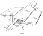
- a belt 53 applied around two drums 51, 52 is provided, in which the drum 52 is fixed rigidly on a shaft 54. Further a sprocket 55 is provided on the shaft 54, which sprocket is driven by means of a chain 56 and a sprocket 57 fixed rigidly on the shaft 47. Further a guide plate 58 is applied near the bend of the L-shaped duct and at the end of the L-shaped duct a guide plate 59 is applied. Subsequently the fixation of the plates to be treated will be described referring to figure 2. A clamp 61 is fixed to the plate 72 to be treated.
- the clamp 61 comprises a plate of resiliant material bended to form two clamp jaws 62, 63 which are urged resiliantly to eachother.
- the clamp jaws comprise each a row of teeth 64, 65 which engage the plate 72 to be clamped and to be processed.
- a tongue 66 entends to the other clamping jaw.
- Each of these tongues 66 comprises a hole through which extends a shaft 62.
- a brace 68 is rigidly provided, while on each end of the shaft 67 a operating knob 69 is provided. By turning the operating knob 69 the brace urges the clamping jaws from eachother to allow to insert or to remove a plate between the row of teeth 64, 65.
- a shaft 70 extends between the clamping jaws 62, 63 unto both sides of the clamping jaws 62, 63.
- a printing plate 72 to be treated is clamped between the rows of teeth 64, 65. Then the shaft 70 of the clamp 61 is hooked behind a pair of hooks provided on the belt 36, so that the clamp 61 and the plate 72 to be treated are drawn into the apparatus, wherein the plate 72 is supported by the guide plate 71.
- the plate 72 is processed by the rotating brushes 13 to a processing by the liquid 6, during which processing the plate 72 is conveyed slowly by the belt 30.
- the plate 72 is pressed against the belt and against the pressing plate 60.
- the plate 72 is further being conveyed alongside the brushes 12 in a basin.4 and subsequently along the brushes 11 in the basin 3.
- the liquid considerably polluted and used in the first basin is supplied to the middle basin 4, where the plates 72 are being adapted to a first processing. From the middle basin 4 the liquid which increases to be polluted is supplied to the last basin 5, where the plates are being subjected to a first washing treatment.
- the plate 72 is conveyed along the suction nozzle 22, where the liquid adhering to the plate 72 is being sucked off.
- the belt 30 then leads the plate 72 along three consecutive nozzles which spray warm air to the plate 30 to dry the plate 72.
Landscapes
- Physics & Mathematics (AREA)
- General Physics & Mathematics (AREA)
- Cleaning In General (AREA)
- Drying Of Solid Materials (AREA)
- Inking, Control Or Cleaning Of Printing Machines (AREA)
Applications Claiming Priority (2)
| Application Number | Priority Date | Filing Date | Title |
|---|---|---|---|
| NL8503402 | 1985-12-10 | ||
| NL8503402A NL8503402A (nl) | 1985-12-10 | 1985-12-10 | Inrichting voor het met een vloeistof behandelen van drukplaten. |
Publications (2)
| Publication Number | Publication Date |
|---|---|
| EP0225678A1 true EP0225678A1 (de) | 1987-06-16 |
| EP0225678B1 EP0225678B1 (de) | 1990-03-14 |
Family
ID=19846992
Family Applications (1)
| Application Number | Title | Priority Date | Filing Date |
|---|---|---|---|
| EP19860202235 Expired EP0225678B1 (de) | 1985-12-10 | 1986-12-10 | Vorrichtung zur Behandlung von Druckplatten mit einer Flüssigkeit |
Country Status (3)
| Country | Link |
|---|---|
| EP (1) | EP0225678B1 (de) |
| DE (1) | DE3669597D1 (de) |
| NL (1) | NL8503402A (de) |
Cited By (12)
| Publication number | Priority date | Publication date | Assignee | Title |
|---|---|---|---|---|
| US4952961A (en) * | 1988-07-28 | 1990-08-28 | Machinehandel Houtstra Bv | Apparatus for processing a printing plate with a liquid |
| FR2695738A1 (fr) * | 1992-09-17 | 1994-03-18 | Du Pont | Procédé de production de plaques d'impression flexographique photopolymérisables. |
| FR2695736A1 (fr) * | 1992-09-17 | 1994-03-18 | Du Pont | Appareil de lavage de plaques d'impression flexographique. |
| DE4231103A1 (de) * | 1992-09-17 | 1994-03-24 | Du Pont Deutschland | Verfahren zum Transport einer flexographischen Druckplatte durch eine Bearbeitungsvorrichtung und Vorrichtung zur Herstellung flexographischer Druckplatten |
| US5557857A (en) * | 1992-09-17 | 1996-09-24 | E. I. Du Pont De Nemours And Company | Apparatus for the aftertreatment of photopolymerizable printing plates |
| WO2019050490A1 (en) * | 2017-09-11 | 2019-03-14 | Mega Elektromekani̇k Maki̇na İmalat İthalat İhracat Sanayi̇ Ve Ti̇caret Li̇mi̇ted Şi̇rketi̇ | SYSTEM AND METHOD FOR ONLINE PROCESSING OF WATER-WASHABLE FLEXOGRAPHIC PHOTOPOLYMER PRINTING PLATES |
| WO2019206906A1 (en) * | 2018-04-26 | 2019-10-31 | Xeikon Prepress N.V. | Apparatus and method for treating and transporting a relief printing plate precursor |
| NL2020835B1 (en) * | 2018-04-26 | 2019-11-05 | Xeikon Prepress Nv | Apparatus and method for treating a relief plate precursor |
| NL2020836B1 (en) * | 2018-04-26 | 2019-11-05 | Xeikon Prepress Nv | Apparatus and method for treating a relief plate precursor |
| WO2020208145A1 (en) * | 2019-04-11 | 2020-10-15 | Xeikon Prepress N.V. | Apparatus and method for treating a relief printing plate precursor with liquid |
| WO2021198012A1 (en) * | 2020-03-30 | 2021-10-07 | Xeikon Prepress N.V. | Apparatus and method for treating a relief plate precursor with improved liquid evacuation |
| PL244692B1 (pl) * | 2021-02-16 | 2024-02-26 | Print Systems Spolka Z Ograniczona Odpowiedzialnoscia Spolka Komandytowa | Automatyczny podajnik matryc flexograficznych i/lub typograficznych |
Citations (5)
| Publication number | Priority date | Publication date | Assignee | Title |
|---|---|---|---|---|
| GB1212317A (en) * | 1968-05-28 | 1970-11-11 | Ewald Puls | Apparatus for the automatic developing of printing plates |
| FR2054129A5 (de) * | 1969-07-07 | 1971-04-16 | Bio Bielefelder Offset | |
| FR2225217A1 (de) * | 1973-04-16 | 1974-11-08 | Kalle Ag | |
| US4004045A (en) * | 1974-08-09 | 1977-01-18 | Stelter Manfred K | Method for fluid film application |
| US4213420A (en) * | 1978-08-09 | 1980-07-22 | Martino Peter V | Apparatus for processing a particulating printing plate |
-
1985
- 1985-12-10 NL NL8503402A patent/NL8503402A/nl not_active Application Discontinuation
-
1986
- 1986-12-10 EP EP19860202235 patent/EP0225678B1/de not_active Expired
- 1986-12-10 DE DE8686202235T patent/DE3669597D1/de not_active Expired - Lifetime
Patent Citations (5)
| Publication number | Priority date | Publication date | Assignee | Title |
|---|---|---|---|---|
| GB1212317A (en) * | 1968-05-28 | 1970-11-11 | Ewald Puls | Apparatus for the automatic developing of printing plates |
| FR2054129A5 (de) * | 1969-07-07 | 1971-04-16 | Bio Bielefelder Offset | |
| FR2225217A1 (de) * | 1973-04-16 | 1974-11-08 | Kalle Ag | |
| US4004045A (en) * | 1974-08-09 | 1977-01-18 | Stelter Manfred K | Method for fluid film application |
| US4213420A (en) * | 1978-08-09 | 1980-07-22 | Martino Peter V | Apparatus for processing a particulating printing plate |
Cited By (26)
| Publication number | Priority date | Publication date | Assignee | Title |
|---|---|---|---|---|
| US4952961A (en) * | 1988-07-28 | 1990-08-28 | Machinehandel Houtstra Bv | Apparatus for processing a printing plate with a liquid |
| US5365629A (en) * | 1992-09-17 | 1994-11-22 | E. I. Du Pont De Nemours And Company | Apparatus for washing out flexographic printing plates |
| FR2695738A1 (fr) * | 1992-09-17 | 1994-03-18 | Du Pont | Procédé de production de plaques d'impression flexographique photopolymérisables. |
| DE4231103A1 (de) * | 1992-09-17 | 1994-03-24 | Du Pont Deutschland | Verfahren zum Transport einer flexographischen Druckplatte durch eine Bearbeitungsvorrichtung und Vorrichtung zur Herstellung flexographischer Druckplatten |
| US5552262A (en) * | 1992-09-17 | 1996-09-03 | E. I. Du Pont De Nemours And Company | Process for production of photopolymerizable flexographic printing plates |
| US5557857A (en) * | 1992-09-17 | 1996-09-24 | E. I. Du Pont De Nemours And Company | Apparatus for the aftertreatment of photopolymerizable printing plates |
| FR2695736A1 (fr) * | 1992-09-17 | 1994-03-18 | Du Pont | Appareil de lavage de plaques d'impression flexographique. |
| US11052653B2 (en) | 2017-09-11 | 2021-07-06 | Mega Elektromekanik Makina Imalat Ithalat Ihracat Sanayi Ve Ticaret Limited Sirketi | System and method for in-line processing of water washable flexo photopolymer printing plates |
| WO2019050490A1 (en) * | 2017-09-11 | 2019-03-14 | Mega Elektromekani̇k Maki̇na İmalat İthalat İhracat Sanayi̇ Ve Ti̇caret Li̇mi̇ted Şi̇rketi̇ | SYSTEM AND METHOD FOR ONLINE PROCESSING OF WATER-WASHABLE FLEXOGRAPHIC PHOTOPOLYMER PRINTING PLATES |
| NL2020835B1 (en) * | 2018-04-26 | 2019-11-05 | Xeikon Prepress Nv | Apparatus and method for treating a relief plate precursor |
| WO2019206906A1 (en) * | 2018-04-26 | 2019-10-31 | Xeikon Prepress N.V. | Apparatus and method for treating and transporting a relief printing plate precursor |
| NL2020836B1 (en) * | 2018-04-26 | 2019-11-05 | Xeikon Prepress Nv | Apparatus and method for treating a relief plate precursor |
| WO2019206911A1 (en) * | 2018-04-26 | 2019-10-31 | Xeikon Prepress N.V. | Apparatus and method for treating a relief plate precursor having a transport system |
| EP4614232A3 (de) * | 2018-04-26 | 2025-11-19 | XSYS Prepress N.V. | Vorrichtung und verfahren zur behandlung eines reliefplattenvorläufers |
| US20210362530A1 (en) * | 2018-04-26 | 2021-11-25 | Xeikon Prepress N.V. | Apparatus and method for treating a relief plate precursor having a transport system |
| US12078932B2 (en) * | 2018-04-26 | 2024-09-03 | Xsys Prepress N.V. | Apparatus and method for treating a relief plate precursor having a transport system |
| US11953834B2 (en) | 2018-04-26 | 2024-04-09 | Xsys Prepress N.V. | Apparatus and method for treating and transporting a relief printing plate precursor |
| WO2020208145A1 (en) * | 2019-04-11 | 2020-10-15 | Xeikon Prepress N.V. | Apparatus and method for treating a relief printing plate precursor with liquid |
| CN114126774A (zh) * | 2019-04-11 | 2022-03-01 | 赛康印前公众有限公司 | 用液体处理凸版印刷版前体的装置和方法 |
| CN114126774B (zh) * | 2019-04-11 | 2024-05-07 | 阿合斯印前有限公司 | 用液体处理凸版印刷版前体的装置和方法 |
| US12023907B2 (en) | 2019-04-11 | 2024-07-02 | Xsys Prepress N.V. | Apparatus and method for treating a relief printing plate precursor with liquid |
| NL2022926B1 (en) * | 2019-04-11 | 2020-10-20 | Xeikon Prepress Nv | Apparatus and method for treating a relief precursor with liquid |
| NL2025238B1 (en) * | 2020-03-30 | 2021-10-22 | Xeikon Prepress Nv | Apparatus and method for treating a relief plate precursor with improved liquid evacuation |
| WO2021198012A1 (en) * | 2020-03-30 | 2021-10-07 | Xeikon Prepress N.V. | Apparatus and method for treating a relief plate precursor with improved liquid evacuation |
| US12447733B2 (en) | 2020-03-30 | 2025-10-21 | Xsys Prepress N.V. | Apparatus and method for treating a relief plate precursor with improved liquid evacuation |
| PL244692B1 (pl) * | 2021-02-16 | 2024-02-26 | Print Systems Spolka Z Ograniczona Odpowiedzialnoscia Spolka Komandytowa | Automatyczny podajnik matryc flexograficznych i/lub typograficznych |
Also Published As
| Publication number | Publication date |
|---|---|
| DE3669597D1 (de) | 1990-04-19 |
| EP0225678B1 (de) | 1990-03-14 |
| NL8503402A (nl) | 1986-08-01 |
Similar Documents
| Publication | Publication Date | Title |
|---|---|---|
| EP0225678B1 (de) | Vorrichtung zur Behandlung von Druckplatten mit einer Flüssigkeit | |
| US5268100A (en) | Manure separator | |
| CA2192010C (en) | Sludge processor | |
| KR102143204B1 (ko) | 멸치자숙용 발 세척장치 | |
| EP0771745A1 (de) | Verfahren und Vorrichtung zum Waschen und hygienischer Reinigung von Förderbändern,insbesondere für die Ernährungsmittel- Industrie | |
| KR100420106B1 (ko) | 마른 고추 세척장치 | |
| SE7902440L (sv) | Anordning for behandling av hellbart gods | |
| US2503556A (en) | Vegetable washer | |
| WO2003015946A1 (en) | Mat cleaning apparatus | |
| US4408364A (en) | Apparatus for washing an aloe vera leaf | |
| US4542968A (en) | Device for treating photo printing plates | |
| WO2005068665A1 (en) | Apparatus and method for processing fur | |
| EP0322252A2 (de) | Vorrichtung und Verfahren zum Schälen von Kartoffeln und ähnlichen Produkten | |
| US5749155A (en) | Device for removing liquid on a gauze conveyor and hollow roll comprising a tube for use in such a device | |
| US1852405A (en) | Fruit washer and drier | |
| KR200190667Y1 (ko) | 밤탈피장치 | |
| US2632901A (en) | Egg washing machine and roller therefor | |
| US2791798A (en) | Poultry gizzard skinner | |
| JPH11155413A (ja) | 卵の処理装置 | |
| KR200424958Y1 (ko) | 김치 제조용 염수 세척 장치 | |
| US5365629A (en) | Apparatus for washing out flexographic printing plates | |
| US1750612A (en) | Vegetable washer | |
| US3105255A (en) | Machine for cleaning elongated objects | |
| US3157285A (en) | Cotton cleaner | |
| CN216255300U (zh) | 一种用于猕猴桃除尘去毛的清洗装置 |
Legal Events
| Date | Code | Title | Description |
|---|---|---|---|
| PUAI | Public reference made under article 153(3) epc to a published international application that has entered the european phase |
Free format text: ORIGINAL CODE: 0009012 |
|
| AK | Designated contracting states |
Kind code of ref document: A1 Designated state(s): DE FR NL |
|
| 17P | Request for examination filed |
Effective date: 19871216 |
|
| 17Q | First examination report despatched |
Effective date: 19881122 |
|
| GRAA | (expected) grant |
Free format text: ORIGINAL CODE: 0009210 |
|
| AK | Designated contracting states |
Kind code of ref document: B1 Designated state(s): DE FR NL |
|
| REF | Corresponds to: |
Ref document number: 3669597 Country of ref document: DE Date of ref document: 19900419 |
|
| ET | Fr: translation filed | ||
| PLBE | No opposition filed within time limit |
Free format text: ORIGINAL CODE: 0009261 |
|
| STAA | Information on the status of an ep patent application or granted ep patent |
Free format text: STATUS: NO OPPOSITION FILED WITHIN TIME LIMIT |
|
| 26N | No opposition filed | ||
| REG | Reference to a national code |
Ref country code: FR Ref legal event code: TP |
|
| NLS | Nl: assignments of ep-patents |
Owner name: FIRMA WINDMOELLER & HOELSCHER TE LENGERICH, BONDSR |
|
| NLS | Nl: assignments of ep-patents |
Owner name: E.I. DU PONT DE NEMOURS AND COMPANY TE WILMINGTON, |
|
| REG | Reference to a national code |
Ref country code: FR Ref legal event code: TP |
|
| PGFP | Annual fee paid to national office [announced via postgrant information from national office to epo] |
Ref country code: NL Payment date: 20011228 Year of fee payment: 16 |
|
| PG25 | Lapsed in a contracting state [announced via postgrant information from national office to epo] |
Ref country code: NL Free format text: LAPSE BECAUSE OF NON-PAYMENT OF DUE FEES Effective date: 20030701 |
|
| NLV4 | Nl: lapsed or anulled due to non-payment of the annual fee |
Effective date: 20030701 |
|
| PGFP | Annual fee paid to national office [announced via postgrant information from national office to epo] |
Ref country code: FR Payment date: 20050825 Year of fee payment: 20 |
|
| PGFP | Annual fee paid to national office [announced via postgrant information from national office to epo] |
Ref country code: DE Payment date: 20051209 Year of fee payment: 20 |