EP0225682A1 - Testen von Fernmeldekabeln - Google Patents
Testen von Fernmeldekabeln Download PDFInfo
- Publication number
- EP0225682A1 EP0225682A1 EP86305857A EP86305857A EP0225682A1 EP 0225682 A1 EP0225682 A1 EP 0225682A1 EP 86305857 A EP86305857 A EP 86305857A EP 86305857 A EP86305857 A EP 86305857A EP 0225682 A1 EP0225682 A1 EP 0225682A1
- Authority
- EP
- European Patent Office
- Prior art keywords
- conductor
- conductors
- cable
- face
- solid mass
- Prior art date
- Legal status (The legal status is an assumption and is not a legal conclusion. Google has not performed a legal analysis and makes no representation as to the accuracy of the status listed.)
- Granted
Links
- 238000012360 testing method Methods 0.000 title claims abstract description 40
- 239000004020 conductor Substances 0.000 claims abstract description 120
- 239000000523 sample Substances 0.000 claims abstract description 37
- 239000007787 solid Substances 0.000 claims abstract description 33
- 239000000463 material Substances 0.000 claims abstract description 19
- 239000003989 dielectric material Substances 0.000 claims abstract description 8
- 238000000034 method Methods 0.000 claims description 25
- 238000012544 monitoring process Methods 0.000 claims description 5
- 238000010998 test method Methods 0.000 claims description 5
- 230000001419 dependent effect Effects 0.000 claims description 3
- 238000005259 measurement Methods 0.000 abstract description 3
- 230000009969 flowable effect Effects 0.000 abstract 1
- 239000011162 core material Substances 0.000 description 12
- 230000008569 process Effects 0.000 description 7
- 230000007246 mechanism Effects 0.000 description 4
- 239000003822 epoxy resin Substances 0.000 description 3
- 229920000647 polyepoxide Polymers 0.000 description 3
- 238000002360 preparation method Methods 0.000 description 3
- 229920005989 resin Polymers 0.000 description 2
- 239000011347 resin Substances 0.000 description 2
- 230000015572 biosynthetic process Effects 0.000 description 1
- 150000001875 compounds Chemical class 0.000 description 1
- 238000005520 cutting process Methods 0.000 description 1
- 238000010586 diagram Methods 0.000 description 1
- 230000008030 elimination Effects 0.000 description 1
- 238000003379 elimination reaction Methods 0.000 description 1
- 238000004519 manufacturing process Methods 0.000 description 1
- 238000012986 modification Methods 0.000 description 1
- 230000004048 modification Effects 0.000 description 1
- 238000000465 moulding Methods 0.000 description 1
- 230000037361 pathway Effects 0.000 description 1
- 230000008439 repair process Effects 0.000 description 1
- 230000000717 retained effect Effects 0.000 description 1
- 230000009897 systematic effect Effects 0.000 description 1
- 238000012956 testing procedure Methods 0.000 description 1
Images

Classifications
-
- G—PHYSICS
- G01—MEASURING; TESTING
- G01R—MEASURING ELECTRIC VARIABLES; MEASURING MAGNETIC VARIABLES
- G01R31/00—Arrangements for testing electric properties; Arrangements for locating electric faults; Arrangements for electrical testing characterised by what is being tested not provided for elsewhere
- G01R31/50—Testing of electric apparatus, lines, cables or components for short-circuits, continuity, leakage current or incorrect line connections
- G01R31/58—Testing of lines, cables or conductors
- G01R31/60—Identification of wires in a multicore cable
-
- G—PHYSICS
- G01—MEASURING; TESTING
- G01R—MEASURING ELECTRIC VARIABLES; MEASURING MAGNETIC VARIABLES
- G01R31/00—Arrangements for testing electric properties; Arrangements for locating electric faults; Arrangements for electrical testing characterised by what is being tested not provided for elsewhere
- G01R31/50—Testing of electric apparatus, lines, cables or components for short-circuits, continuity, leakage current or incorrect line connections
- G01R31/58—Testing of lines, cables or conductors
Definitions
- This invention relates to the testing of telecommunications cables.
- every single conductor pair is tested to determine whether there are any electrical shorts between each wire and any other wire of the cable or any breakage in any wire.
- the test required for this is performed in two stages. In a first stage, at one end of the cable all the electrical conductors are electrically isolated from each other. At the other end of the cable the wires are electrically connected to each other. Then each individual wire is removed from this common connection and is placed exteriorly of the cable in an electrical circuit in which the wire is connected in series with the common connection of all the other wires.
- the present invention is concerned with a method of testing conductors of a telecommunications cable and also with an apparatus to enable the method to be used and in which a complete cable may be tested, not only for faults, but also for its characteristics in a much shorter period of time.
- the method of the invention is concerned with testing electrical cable and involves the holding of the conductor ends at one end of the cable in fixed relative positions and electrically isolated from one another and of then passing an electrical current through a probe and into each conductor in turn to enable the value of any desired electrical property to be measured.
- the conductor end portions are embedded in a solid mass of material and some of the material is then removed to form a planar end face with the conductor ends terminating and exposed at this end face.
- the present invention provides a method of electrically testing conductors of a telecommunications cable having a cable core which comprises a plurality of individually insulated electrical conductors in which the method comprises providing the core with one end which is stripped of surrounding cable material, with the insulated conductor ends at said one end separated from one another, causing a flowing hardenable dielectric material to fill spaces between the conductors, hardening the material to form a solid mass in which conductor end portions are embedded in fixed relative positions and are electrically isolated from one another, removing some of the hardened material and part of each conductor end portion, to provide a planar end face of the solid mass with the electrically isolated conductor ends terminating at and exposed at the end face, and sequentially contacting the exposed ends of conductors to be tested with an electrically conductive probe, passing an electrical current through the probe and into any conductor which it contacts, and measuring the value of a desired electrical property as the current passes along the conductor.
- the method preferably comprises forming the solid mass from a material which reflects light at a different intensity from that of the conductor ends and after providing the planar end face, monitoring the light reflected from it.
- this monitored light is then converted into signals in which the light signals for the conductor ends differ from those for the solid mass, and these signals are stored in a memory.
- the probe is then moved, dependent upon the stored signals, from one conductor position to another automatically so as to contact sequentially, each conductor to be tested.
- the preferred method avoids any manual tedium for the testing process.
- the invention includes apparatus for the electrical testing of conductors of a telecommunications cable which comprises means for embedding conductor ends at one end of a cable core in spaced relationship within a solid mass of dielectric material, a work station for holding said one end of cable core and the solid mass in fixed position after a planar end face has been provided in the solid mass at the core end, probe means movable into positions to contact exposed ends of conductors at the planar end face, the probe means connectable to a source of electrical potential, and control means for moving the probe means into contact with the exposed ends of the conductors.
- the apparatus includes means for monitoring light reflected from the planar end face and for converting it to electrical signals, memory means for storing the signals, the control means movable dependently upon the stored signals to move the energy transmitting means into said positions.
- a cable 10 which is carried upon a reel 12 has its outer coiled end prepared for testing.
- This preparation involves the removal of the cable jacket and sheath 14 to expose end portions 16 of the insulated electrical conductors of the cable core. Sufficient jacket and sheath should be removed to enable the test procedure to take place.
- the conductor end portions tend to spring away from each other as shown in Figure 1 so that the twisted together pairs of conductors become separated. These separated pairs are then embedded within a solid mass of hardened dielectric material 18 as shown in Figure 2.
- the solid mass is molded into position around the conductor end portions with a molten epoxy resin material or other fast curing compound.
- a simple mold is provided in the form of a container 20 which may be split to remove it from the molded mass. This is placed on the ground, the molten epoxy resin material poured into it, and the conductor end portions inserted into the container to be immersed in the material as shown in Figure 2, thereby providing a seal with the jacket to prevent or restrain the flowing resin from flowing along the jacket.
- the cable mounted upon its reel is then located with the outer end held in a work station, i.e. in an aperture in a work table 26.
- a work station i.e. in an aperture in a work table 26.
- the jacket and the solid mass are both held by a clamping arrangement in the work table.
- the insulated conductors without surrounding jacket and sheath extend for a suitable distance beneath the table to enable specific faulty conductors to be located upon a fault being found during a test operation as will be described.
- the testing apparatus also comprises a video camera 34 which is disposed above the table 26 and is directed downwardly towards it.
- the camera is mounted upon a bracket 36 which also carries an electromagnetic energy transmitting contact member in the form of an electrical probe 38 which projects from a housing 40.
- Control means is provided for moving the camera and the bracket together across the table 26.
- This control means comprises a robot mechanism 39, the housing for which is shown and which is movable upon a stand 40.
- control means also comprises a computer 41 retained in a housing 42 together with a test set 43 for making measurements and a signal or memory store 44 which is connected to the camera 34 through an analog to digital converter 46 to receive signals corresponding to the intensity of light picked up by the camera which thus provides a means for monitoring light reflected from the planar end face of the solid mass.
- the computer is operably connected to the robot mechanism 39 for controlling its movement dependent upon the signals received from the memory.
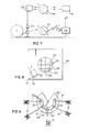
- a grid 50 is secured to any suitable position upon the table 26 ( Figure 7).
- This grid has a plurality of points 52 which reflect light at a different intensity from the background of the grid.
- the camera and the probe 38 are then moved across the grid to determine base line positions with which positions on the surface 22 will then be referenced. This determination is done by locating the probe at each of three of the points 52.
- the positions of these points are then stored in the memory to provide a system or coordinates, i.e. x and y axes, appropriate to the probe 38.
- the camera is then positioned to locate each of the same three points 52.
- Signals are fed from the camera through the converter 46 to the memory 44, these signals corresponding to the intensity of light received from the grid and also received from the points 52 thereby enabling the two axes x and y extending between certain points 52 to be determined appropriate to the camera position and held in the memory.
- the robot 39 is commanded to move the camera across the table to a position directly above the planar end face 22 and the small areas of the end face are dealt with systematically and in order.
- the camera is focused upon a small area of the end face (say for instance that identified by item 53 in Figure 8).
- the light intensity received from this small area by the camera is sent as analog signals to the converter 46 and then into the memory as digital signals wherein it is stored for use when controlling movement of the probe across the area 53.
- the signals received by the memory for the solid mass of material itself differ from those received from the conductor ends, because the reflected light from the conductor ends is different from that of the black solid mass.
- the memory then compares the signals for the conductor ends with the positions for the axes x and y.
- the computer then controls the movement of the probe from the information stored in the memory concerning the conductor positions relative to the x and y axes which are related to both the camera and probe positions.
- the robot mechanism 39 is moved intermittently to position the probe sequentially directly above each of the conductor ends. When above each conductor end, the probe is moved into contact with the conductor end for passing a current through it.
- each conductor end is dealt with in the particular frame of reference, i.e. the area 53.
- the camera moves to the next area, for instance area 54 and the same procedure is followed, i.e.
- the total process which has been described above including the removal of the jacket sheath, formation of the solid mass and the testing of each individual conductor is exceedingly short as compared to a standard testing operation. For instance, it has been found that after the jacket and sheath material has been removed, a period of about 15 minutes is required for molding, about 60 minutes is required for the epoxy resin to harden and to be ground down to provide the end face.
- the probe is moved from wire to wire at a speed of about 3 wires per second during one testing operation which is performed to determine whether an electrical short has been produced between any conductor and any other conductor.
- this total operation takes around 40 minutes compared to a conventional test for indicating electrical pathways between conductors and which normally takes about 4 hours.
- the process may be accelerated by preparing succeeding cables for testing while one cable is being tested.
- This is indicated by Figure 9 in which the robot mechanism is disposed substantially on the center of an arcuate table 58 in which a plurality i.e. five, work stations 60 are provided.
- Figure 9 shows the camera being traversed across one of these work stations while the other work stations are being made ready for test purposes.
- previously prepared cables 10 are already disposed for testing, and each of the cables has already been formed with it solid mass at an outer cable end and with its planar end face 22 which is already held securely in position in the work station in a similar way to that shown in Figure 5.
- the total test time for individual cables is reduced substantially because of this overlap of operations.
- test procedure may be performed upon the apparatus described above, the test being done in two stages as will be described.
- the conductors at one end of the cable are shorted to ground or to each other.
- the probe is then passed under robot control across the end face 22 at the other end of the cable and passes current, in turn, into each conductor.
- the resistance to the current is then measured to determine for any wire breakage. As resistance may be affected by the pressure of any probe upon a conductor and also upon the conductor temperature, inductance is also measured, because from inductance a more accurate resistance may be determined. Any differences in inductance from what should be expected will indicate a broken conductor.
Landscapes
- Physics & Mathematics (AREA)
- General Physics & Mathematics (AREA)
- Testing Of Short-Circuits, Discontinuities, Leakage, Or Incorrect Line Connections (AREA)
- Locating Faults (AREA)
- Input Circuits Of Receivers And Coupling Of Receivers And Audio Equipment (AREA)
- Communication Cables (AREA)
- Monitoring And Testing Of Exchanges (AREA)
Applications Claiming Priority (2)
| Application Number | Priority Date | Filing Date | Title |
|---|---|---|---|
| CA494213 | 1985-10-30 | ||
| CA000494213A CA1262373A (en) | 1985-10-30 | 1985-10-30 | Testing of telecommunication cables |
Publications (2)
| Publication Number | Publication Date |
|---|---|
| EP0225682A1 true EP0225682A1 (de) | 1987-06-16 |
| EP0225682B1 EP0225682B1 (de) | 1991-01-02 |
Family
ID=4131750
Family Applications (1)
| Application Number | Title | Priority Date | Filing Date |
|---|---|---|---|
| EP86305857A Expired - Lifetime EP0225682B1 (de) | 1985-10-30 | 1986-07-30 | Testen von Fernmeldekabeln |
Country Status (7)
| Country | Link |
|---|---|
| US (1) | US4794339A (de) |
| EP (1) | EP0225682B1 (de) |
| JP (1) | JPS62106375A (de) |
| CA (1) | CA1262373A (de) |
| DE (1) | DE3676465D1 (de) |
| FI (1) | FI864409A7 (de) |
| NO (1) | NO863676L (de) |
Cited By (2)
| Publication number | Priority date | Publication date | Assignee | Title |
|---|---|---|---|---|
| AU616250B2 (en) * | 1988-04-18 | 1991-10-24 | Ergon Energy Corporation Limited | Instrument transformer testing apparatus |
| FR2670298A1 (fr) * | 1990-12-10 | 1992-06-12 | Aerospatiale | Systeme pour tester la continuite electrique et l'isolement des conducteurs electriques d'une piece de cablage. |
Families Citing this family (10)
| Publication number | Priority date | Publication date | Assignee | Title |
|---|---|---|---|---|
| US4928066A (en) * | 1989-04-07 | 1990-05-22 | Amp Incorporated | Continuity coupling in a harness making machine |
| CA2061670C (en) * | 1991-02-21 | 1998-02-03 | Masaru Yamaguchi | Detection system for abnormal cable connections in communications apparatuses |
| EP0541843B1 (de) * | 1991-11-12 | 1997-01-15 | Molex Incorporated | Drahtanwesenheits- und Identifiziersystem |
| US5543718A (en) * | 1994-04-08 | 1996-08-06 | Dcm Industries, Inc. | Cable testing device |
| US6621276B2 (en) * | 2000-12-26 | 2003-09-16 | Pirelli Cavi E Sistemi S.P.A. | Termination assembly for power cable testing and methods for its use |
| US20030152153A1 (en) * | 2002-02-14 | 2003-08-14 | Simon Thomas D. | Signaling through electromagnetic couplers |
| US7088198B2 (en) | 2002-06-05 | 2006-08-08 | Intel Corporation | Controlling coupling strength in electromagnetic bus coupling |
| US6887095B2 (en) | 2002-12-30 | 2005-05-03 | Intel Corporation | Electromagnetic coupler registration and mating |
| US9444921B2 (en) * | 2007-10-29 | 2016-09-13 | Centurylink Intellectual Property Llc | System to provide real loops for sidetone measurement with analog telephones |
| US20090114442A1 (en) * | 2007-11-05 | 2009-05-07 | Components Express, Inc. | Camera Link Booster Cable Assembly |
Citations (3)
| Publication number | Priority date | Publication date | Assignee | Title |
|---|---|---|---|---|
| DD51676A (de) * | ||||
| US3252087A (en) * | 1961-06-15 | 1966-05-17 | Marine Electric Corp | Method and apparatus for identifying wires |
| DE1259990B (de) * | 1963-10-01 | 1968-02-01 | Siemens Ag | Anordnung zur Durchfuehrung elektrischer Reihenmessungen an vieladrigen Fernmeldekabeln |
Family Cites Families (3)
| Publication number | Priority date | Publication date | Assignee | Title |
|---|---|---|---|---|
| US3986106A (en) * | 1975-03-31 | 1976-10-12 | Shuck Edward E | Portable set for automatic sequential test of multiple wire pairs |
| US4038501A (en) * | 1975-07-10 | 1977-07-26 | Volk Victor F | Apparatus and method for automatically connecting to the individual conductors of a multiconductor cable |
| US4527119A (en) * | 1982-05-17 | 1985-07-02 | Testamatic, Incorporated | High speed, low mass, movable probe and/or instrument positioner, tool and like items suitable for use in a controlled environment chamber |
-
1985
- 1985-10-30 CA CA000494213A patent/CA1262373A/en not_active Expired
- 1985-11-01 US US06/793,944 patent/US4794339A/en not_active Expired - Fee Related
-
1986
- 1986-07-30 EP EP86305857A patent/EP0225682B1/de not_active Expired - Lifetime
- 1986-07-30 DE DE8686305857T patent/DE3676465D1/de not_active Expired - Fee Related
- 1986-09-15 NO NO863676A patent/NO863676L/no unknown
- 1986-09-30 JP JP61230193A patent/JPS62106375A/ja active Pending
- 1986-10-29 FI FI864409A patent/FI864409A7/fi not_active Application Discontinuation
Patent Citations (3)
| Publication number | Priority date | Publication date | Assignee | Title |
|---|---|---|---|---|
| DD51676A (de) * | ||||
| US3252087A (en) * | 1961-06-15 | 1966-05-17 | Marine Electric Corp | Method and apparatus for identifying wires |
| DE1259990B (de) * | 1963-10-01 | 1968-02-01 | Siemens Ag | Anordnung zur Durchfuehrung elektrischer Reihenmessungen an vieladrigen Fernmeldekabeln |
Cited By (4)
| Publication number | Priority date | Publication date | Assignee | Title |
|---|---|---|---|---|
| AU616250B2 (en) * | 1988-04-18 | 1991-10-24 | Ergon Energy Corporation Limited | Instrument transformer testing apparatus |
| FR2670298A1 (fr) * | 1990-12-10 | 1992-06-12 | Aerospatiale | Systeme pour tester la continuite electrique et l'isolement des conducteurs electriques d'une piece de cablage. |
| EP0490728A1 (de) * | 1990-12-10 | 1992-06-17 | Eurocopter France | Einrichtung zum Testen des elektrischen Durchgangs und der Isolierung elektrischer Leiter einer Verkabelung |
| US5220285A (en) * | 1990-12-10 | 1993-06-15 | Societe Anonyme Die: Aerospatiale Societe Nationale Industrielle | System for testing the electrical continuity and insulation of the electrical conductors of a portion of wiring |
Also Published As
| Publication number | Publication date |
|---|---|
| JPS62106375A (ja) | 1987-05-16 |
| FI864409A0 (fi) | 1986-10-29 |
| US4794339A (en) | 1988-12-27 |
| DE3676465D1 (de) | 1991-02-07 |
| FI864409L (fi) | 1987-05-01 |
| EP0225682B1 (de) | 1991-01-02 |
| FI864409A7 (fi) | 1987-05-01 |
| CA1262373A (en) | 1989-10-17 |
| NO863676L (no) | 1987-05-04 |
| NO863676D0 (no) | 1986-09-15 |
Similar Documents
| Publication | Publication Date | Title |
|---|---|---|
| US4794339A (en) | Method and apparatus for electrically testing telecommunications cables | |
| US4549039A (en) | Telecommunications cable splice closures | |
| US4110880A (en) | Cable harness assembly and electrical testing machine | |
| EP0061811B1 (de) | Vorrichtung zur Positionierung einer elektrischen Leitung und zur Montage eines Steckers an deren Ende | |
| JP4566407B2 (ja) | 地下ケーブルにおける絶縁性低下を診断するための方法 | |
| CN1331805A (zh) | 测试集成电路的引线架结构 | |
| CN111123047B (zh) | 用于电线电缆电压和绝缘电阻试验的一体化自动检测系统 | |
| US4285118A (en) | Cable harness assembly and electrical testing machine | |
| US4947546A (en) | Method of making a cable assembly | |
| EP0482169A1 (de) | Gerät zum automatischen testen von kabelbäumen. | |
| US4901189A (en) | Terminal block and methods of making | |
| US5203721A (en) | Molded plastic coaxial cable side tap connector | |
| FR2661508B1 (fr) | Procede pour verifier l'efficacite du blindage electromagnetique d'un cordon conducteur, et dispositif pour la mise en óoeuvre du procede. | |
| US2862179A (en) | Circuit identifier and tester | |
| US4819329A (en) | Method of manufacturing multiwire lead assemblies | |
| CA2178822C (en) | Method and apparatus for the verification of an electrical insulator device based on the analysis of the electric field along the insulator | |
| US4038501A (en) | Apparatus and method for automatically connecting to the individual conductors of a multiconductor cable | |
| EP0021560B1 (de) | Verfahren zum Feststellen von elektrischen Kurzschlüssen | |
| JPS5875072A (ja) | 通信ケ−ブルカツドの電気特性測定用接続器 | |
| CN115267438A (zh) | 用于测量棒棒空气间隙先导放电电流的装置 | |
| SU1497780A1 (ru) | Способ изготовлени жгутов электропроводов | |
| SU856062A1 (ru) | Способ изготовлени жгута электропроводов | |
| CN121500039A (zh) | 评价高压交流聚丙烯电缆绝缘与屏蔽匹配性的方法及系统 | |
| JPH0524001Y2 (de) | ||
| JPS6150261B2 (de) |
Legal Events
| Date | Code | Title | Description |
|---|---|---|---|
| PUAI | Public reference made under article 153(3) epc to a published international application that has entered the european phase |
Free format text: ORIGINAL CODE: 0009012 |
|
| AK | Designated contracting states |
Kind code of ref document: A1 Designated state(s): DE FR GB NL SE |
|
| 17P | Request for examination filed |
Effective date: 19870803 |
|
| 17Q | First examination report despatched |
Effective date: 19890811 |
|
| GRAA | (expected) grant |
Free format text: ORIGINAL CODE: 0009210 |
|
| AK | Designated contracting states |
Kind code of ref document: B1 Designated state(s): DE FR GB NL SE |
|
| REF | Corresponds to: |
Ref document number: 3676465 Country of ref document: DE Date of ref document: 19910207 |
|
| ET | Fr: translation filed | ||
| PG25 | Lapsed in a contracting state [announced via postgrant information from national office to epo] |
Ref country code: GB Effective date: 19910730 |
|
| PG25 | Lapsed in a contracting state [announced via postgrant information from national office to epo] |
Ref country code: SE Effective date: 19910731 |
|
| PLBE | No opposition filed within time limit |
Free format text: ORIGINAL CODE: 0009261 |
|
| STAA | Information on the status of an ep patent application or granted ep patent |
Free format text: STATUS: NO OPPOSITION FILED WITHIN TIME LIMIT |
|
| 26N | No opposition filed | ||
| PG25 | Lapsed in a contracting state [announced via postgrant information from national office to epo] |
Ref country code: NL Effective date: 19920201 |
|
| NLV4 | Nl: lapsed or anulled due to non-payment of the annual fee | ||
| GBPC | Gb: european patent ceased through non-payment of renewal fee | ||
| PG25 | Lapsed in a contracting state [announced via postgrant information from national office to epo] |
Ref country code: FR Effective date: 19920331 |
|
| PG25 | Lapsed in a contracting state [announced via postgrant information from national office to epo] |
Ref country code: DE Effective date: 19920401 |
|
| REG | Reference to a national code |
Ref country code: FR Ref legal event code: ST |
|
| EUG | Se: european patent has lapsed |
Ref document number: 86305857.4 Effective date: 19920210 |