EP0225710B1 - Appareil d'impression - Google Patents
Appareil d'impression Download PDFInfo
- Publication number
- EP0225710B1 EP0225710B1 EP86308242A EP86308242A EP0225710B1 EP 0225710 B1 EP0225710 B1 EP 0225710B1 EP 86308242 A EP86308242 A EP 86308242A EP 86308242 A EP86308242 A EP 86308242A EP 0225710 B1 EP0225710 B1 EP 0225710B1
- Authority
- EP
- European Patent Office
- Prior art keywords
- character
- wheel
- hammer
- band
- printing
- Prior art date
- Legal status (The legal status is an assumption and is not a legal conclusion. Google has not performed a legal analysis and makes no representation as to the accuracy of the status listed.)
- Expired
Links
- 238000007639 printing Methods 0.000 title claims description 74
- 238000005096 rolling process Methods 0.000 claims description 7
- 230000004044 response Effects 0.000 claims description 2
- 230000001419 dependent effect Effects 0.000 claims 3
- 230000001131 transforming effect Effects 0.000 claims 1
- 241000723353 Chrysanthemum Species 0.000 description 98
- 235000005633 Chrysanthemum balsamita Nutrition 0.000 description 98
- 230000001186 cumulative effect Effects 0.000 description 8
- 238000006073 displacement reaction Methods 0.000 description 8
- 238000010586 diagram Methods 0.000 description 7
- 238000000034 method Methods 0.000 description 7
- 230000007246 mechanism Effects 0.000 description 4
- 230000008569 process Effects 0.000 description 4
- 239000000654 additive Substances 0.000 description 3
- 230000000996 additive effect Effects 0.000 description 3
- 230000006872 improvement Effects 0.000 description 3
- 238000010276 construction Methods 0.000 description 2
- 230000007423 decrease Effects 0.000 description 2
- 230000001965 increasing effect Effects 0.000 description 2
- 239000000463 material Substances 0.000 description 2
- 239000007787 solid Substances 0.000 description 2
- 238000004804 winding Methods 0.000 description 2
- 238000004891 communication Methods 0.000 description 1
- 230000008878 coupling Effects 0.000 description 1
- 238000010168 coupling process Methods 0.000 description 1
- 238000005859 coupling reaction Methods 0.000 description 1
- 238000001514 detection method Methods 0.000 description 1
- 230000001939 inductive effect Effects 0.000 description 1
- 239000011159 matrix material Substances 0.000 description 1
- 239000000203 mixture Substances 0.000 description 1
- 230000004048 modification Effects 0.000 description 1
- 238000012986 modification Methods 0.000 description 1
- 230000003287 optical effect Effects 0.000 description 1
- 230000000284 resting effect Effects 0.000 description 1
- 230000003319 supportive effect Effects 0.000 description 1
- 230000007704 transition Effects 0.000 description 1
- 230000007723 transport mechanism Effects 0.000 description 1
Images




Classifications
-
- B—PERFORMING OPERATIONS; TRANSPORTING
- B41—PRINTING; LINING MACHINES; TYPEWRITERS; STAMPS
- B41J—TYPEWRITERS; SELECTIVE PRINTING MECHANISMS, i.e. MECHANISMS PRINTING OTHERWISE THAN FROM A FORME; CORRECTION OF TYPOGRAPHICAL ERRORS
- B41J19/00—Character- or line-spacing mechanisms
- B41J19/18—Character-spacing or back-spacing mechanisms; Carriage return or release devices therefor
- B41J19/20—Positive-feed character-spacing mechanisms
- B41J19/202—Drive control means for carriage movement
-
- B—PERFORMING OPERATIONS; TRANSPORTING
- B41—PRINTING; LINING MACHINES; TYPEWRITERS; STAMPS
- B41J—TYPEWRITERS; SELECTIVE PRINTING MECHANISMS, i.e. MECHANISMS PRINTING OTHERWISE THAN FROM A FORME; CORRECTION OF TYPOGRAPHICAL ERRORS
- B41J1/00—Typewriters or selective printing mechanisms characterised by the mounting, arrangement or disposition of the types or dies
- B41J1/22—Typewriters or selective printing mechanisms characterised by the mounting, arrangement or disposition of the types or dies with types or dies mounted on carriers rotatable for selection
- B41J1/24—Typewriters or selective printing mechanisms characterised by the mounting, arrangement or disposition of the types or dies with types or dies mounted on carriers rotatable for selection the plane of the type or die face being perpendicular to the axis of rotation
Definitions
- the present invention relates to a printing apparatus of the type wherein a print wheel is presented to a hammer mechanism for printing of a character upon paper or other sheet material.
- the print wheel can take the form of a daisy wheel wherein a plurality of type-bearing fingers are held in and elastically restored to the plane of a central supporting disc, or to take the form of a type wheel where the fingers are elastically supported at an angle, typically 90°, to the plane of the central supportive disc.
- the print wheel is rotated until a desired character falls beneath a hammer mechanism which is operated to cause hammer, selected typeface character and ink ribbon to come together onto the paper to leave a printed record.
- a printhead assembly is first positioned where the character is to be typed or printed and the daisy wheel either thereafter or simultaneously with the printhead positioning is rotated until the desired character is under the hammer.
- the hammer is then operated to cause the above described printing operation.
- Separate motors are required to position the print wheel and to position the printhead assembly. At least one of the motors is required to be situated on the printhead assembly severely limiting the degree of miniaturisation possible in such a printer.
- the daisy wheel or other print wheel is required to accelerate and decelerate in two directions inducing bi-directional stress in the daisy wheel or print wheel rotating apparatus.
- the present invention seeks to provide improvement over the prior art by providing a print wheel printer wherein only a single motor is required both for the positioning of the printhead assembly and for the rotary positioning of the print wheel.
- the present invention seeks further to provide improvement over the prior art by allowing that the single motor can be positioned away from the printhead assembly thereby allowing for miniaturisation of the printer to permit the use of a print wheel or daisy wheel printer in those situations where previously only a low quality dot-matrix printer could be used.
- controllers are provided for a print wheel printer wherein the print wheel is rotated bi-directionally towards a desired printed character being beneath the printing hammer.
- the present invention seeks to provide improvement over the prior art by allowing the use of a controller where the print wheel is rotated uni-directionally between successive printing operations thereby allowing by a simple process the enciphering and deciphering of documents such that they may readily be prepared and read but cannot be rapidly deciphered without knowledge of a simple deciphering key and without use of such a uni-directional controller.
- US-A 3 356 199 discloses a high speed printer utilising a continuously rotating type wheel having at least one group of type characters on its face.
- the characters are arranged spirally relative to the centre of the wheel. During the continuous rotation of the wheel it is moved continuously in a plane parallel to the path of the printing line. The spiral arrangement of the characters enables a desired character to be printed with each angular rotation of the wheel.
- the present invention relates to a printing apparatus having a printhead assembly wherein a print wheel is rotatable to present a selected character to a hammer and wherein said printhead assembly is movable relative to a line whereon characters are to be printed at a plurality of spaced printing locations, said apparatus including driving means operative to rotate said print wheel to present in turn, to said hammer, each of a complete ordered set of characters for printing in sympathy with movement of said printhead assembly along said line by a distance equal to the spacing between successive printing locations; said complete set comprising a first character, undisplaced print wheel; each other character in said complete set being displaced on said print wheel to be printed early on said line by a portion of said space between successive printing locations equal to the fraction of the angle occupied by said ordered set measured from said first character whereat said each other character is located.
- the invention is characterised in that said driving means includes a first portion of band, a second portion of band, and a differential wheel; said differential wheel including a first portion of a first diameter for engaging and rolling along said first portion of band and a second portion of a second diameter for engaging and rolling along said second portion of band; said first portion of band being movable in a first direction relative to said line; said second portion of band being simultaneously, equally and oppositely movable with said first portion of band relative to said path; and said differential wheel being bodily displacable along said line a distance equal to the difference between the distance rolled along said first portion of band and the distance rolled along said second portion of band; said print wheel being coupled to rotate in response to rotation of said differential wheel.
- the differential wheel has the print wheel co-axially mounted thereon and is rotated by an endless belt looped around the first and second portions driven either directly by a motor on the printhead carriage assembly or by a motor at an extreme end driving a driven pulley transferring its rotation to the endless band or belt.
- the differential wheel moves the carriage along a fixed path at the same time as the daisy wheel rotates and when any desired character falls beneath a hammer assembly it is typed in the usual manner.
- the typed characters or typeface on the daisy wheel is displaced such that although the printhead carriage assembly does not move an exact character space, necessarily, between typing operations the typed characters are always properly spaced.
- the endless belt wrapped around the differential wheel is replaced by an endless timing belt with teeth engaging first and second portions of first and second diameters of a toothed gear wheel.
- the hammer may be placed at any angle around the daisy wheel. Where the hammer is spaced from the axis of rotation of the daisy wheel along the line of printing the typeface characters are radially displaced along the individual fingers of the daisy wheel and where the hammer is displaced along an axis at 90 ° to the line of printing the typeface characters are tangentially displaced on the individual fingers of the daisy wheel. Where the hammer assembly is in a combination of these positions the typeface characters are displaced by a mixture of tangential and horizontal displacements on the individual fingers of the daisy wheel.
- endless belts of the first and second preferred embodiments are replaced by rigid racks having a transfer roller therebetween.
- the print wheel carriage assembly is moved along the line of printing in any of a number of manners known in the art and a roller rolls along a flat platform disposed along the line of printing for its rolling motion to be coupled to the daisy wheel or print wheel.
- a controller suitable for use with all the preferred embodiments in the present application calculates the number of print wheel positions required to be moved between printing of adjacent characters and ensures that that number of print wheel positions or steps is executed before operation of the hammer mechanism. Because the print wheel always rotates uni-directionally in each sweep along the line of print, the controller allows for simple enciphering either by printing that character a predetermined number of steps further around from the desired character or by providing an incremental off-set such that the printed character is away from the desired printed character by a number of daisy wheel steps which increases by a predetermined number on each occasion of printing. When deciphering such enciphered print it is merely necessary to apply a simple addition process or subtraction process using the known off-sets in the reverse to either of the above described manners in order to achieve rapid deciphering.
- Fig. 1 shows the carriage transport portion of a first preferred embodiment of the present invention.
- a printhead carriage 10 is mounted to slide on a guide rod 12 by means of a bush or sliding bearing 14 in both directions as illustrated by the first arrow 16.
- a differential wheel 18 is mounted on an axle 20 through a mounting hole or opening 22 in the printhead carriage 10 to rotate on the printhead carriage 10 and to transfer any translational forces it may experience to the printhead carriage 10.
- An endless belt or band 24 passes around the differential wheel 18 in a manner later to be described and is supported at its extreme ends by an idler pulley 26 and a driven pulley 28 urged to rotate by a motor 30.
- the printhead carriage assembly 10 in moving along the guide rod 12 moves along a line of printing adjacent to paper, typeribbon and a platen well known in the art and not described in the present application. It is however to be understood that in this and all the other preferred embodiments of the present application that such elements exist in the printing apparatus.
- Fig. 2 shows a cross-sectional view of the differential wheel 18 of the first preferred embodiment shown in Fig. 1.
- the differential wheel 18 is circular and comprises a first portion 32 of a first diameter and a second portion 34 of a second diameter. Walls 36 prevent the endless belt 24 from slipping from the first 32 and second 34 portions of the differential wheel 18.
- Fig. 3 shows the manner in which the endless belt 24 of Fig. 1 is looped around the first 32 and second 34 portions of the differential wheel 18.
- a first portion 38 of the endless belt or band 24 moves, by way of example as illustrated by a second arrow 40 as the driven pulley 28 is rotated by the motor 30.
- a second portion 42 of the belt or band 24 moves, when the first portion moves as indicated by the second arrow 40, as indicated by a third arrow 44, it being understood that if the direction of rotation of the driven pulley 28 were to be reversed, then the direction of the second and third arrows 40, 44 would also be reversed.
- a first loop 46 in the first portion 38 of the belt or band 24 passes around the first portion 32 of the differential wheel 18.
- a second loop 48 in the second portion 42 of the endless belt or band 24 passes around the second portion 34 of the differential wheel 18. Both loops 46, 48 are wound on their respective portion 32, 34 of the differential wheel 18 such that as the driven pulley 28 is rotated by the motor 30 both loops 46, 48 cause the differential wheel 18 to be urged to rotate in the same angular sense and direction.
- the first loop 46 around the first portion 32 of the differential wheel 18 causes the differential wheel 18 to rotate and the first portion 32 of the differential wheel 18 moves along the first portion 38 of the belt or band 24 by a first distance.
- the second loop 48 in the second portion 42 of the endless belt 24 causes, by engagement with the second portion 34 of the differential wheel 18, the differential wheel 18 to rotate in the same sense as the first loop 46 causes the differential wheel 18 to rotate.
- the second loop 48 thus tends to cause the differential wheel 18 to move along the second portion 42 of the endless belt or band 24 by a second distance.
- the differential motion of the first 38 and second 42 portions of band in opposite directions by equal amounts as indicated by the second 40 and third 44 arrows means that the axle 20 of the differential wheel 18 moves the printhead carriage 10 along the guide rod 12 by a distance equal to the difference that the differential wheel 18 rolls respectively along the first portion 32 of the differential wheel 18 and the second portion 34 of the differential wheel 18.
- the distance moved along the guide rod 12 for each rotation of the driven pulley 28 can be controlled by selection of the ratio of the diameters of the first 32 and second 34 portions of the differential wheel 18.
- the printhead carriage 10 may be caused to move along the guide rod 12 as much or as little distance as is desired per driven pulley 28 revolution.
- carriage 10 Whilst in this embodiment the carriage 10 has been shown as being constrained to move along a line of printing by a guide rod 12 it is to be understood that any system of grooves guides recesses or wires can be used for the same purpose.
- the motor 30 can be a stepping motor wherein a plurality of stable positions per revolution is provided, the position of the carriage 10 being determined by counting the number of steps. Equally, the motor 30 can be a directly driven motor driving either directly or indirectly some form of rotational position encoder whose output is indicative of the rotation of a shaft of the motor.
- Fig. 4 shows a modification on the preferred embodiment shown in Fig. 1 where the idler pulley 26 and the driven pulley 28 have been replaced by a pair of idling wheels 50 supporting the endless belt or band 24 at its extreme ends.
- the motor 30 is transferred from the body of the printing apparatus where it is stationary in Fig. 1 to the printhead carriage 10 itself where it drives the differential wheel 18 either directly or through a gear box mechanism.
- the rotation imparted to the differential wheel 18 causes paying out of the endless belt or band 24 equally and oppositely in each direction along the line of printing, the difference in circumferential distance travelled in the first 32 and second 34 portions of the differential wheel 18 once again being taken up by movement of the carriage 10 along the guide rod 12.
- Fig. 5 shows a second preferred transport mechanism in the present invention constituting a second preferred embodiment.
- the endless band 24 is replaced by an endless toothed timing belt having a first portion 52 resting with its teeth engaged with a first portion 54 having a first diameter of a differential gear wheel 56.
- a second portion 58 of the endless timing belt engages its teeth with teeth in a second portion 60 having a second diameter of the differential gear wheel 56.
- Pressure rolls 62 urge the first 52 and second 58 portions of the timing belt onto the first 54 and second 60 portions of the differential gear wheel 56 as indicated by fourth 64 and fifth 66 arrows.
- the differential gear wheel 56 is fixed to the printhead carriage 10 in the same manner as the differential wheel 18 and similarly translates the carriage 10 along the guide rod 12.
- first 46 and second 48 loops are shown as comprising a single turn around the first 32 and second 34 portions of the differential wheel 18, they may comprise more than one turn.
- Fig. 6 shows how a daisy wheel is affixed to rotate with the differential wheel 18 or the differential gear wheel 56 of the first and second preferred embodiments.
- the daisy wheel 68 is centrally mounted coaxially on the axle 20 to rotate with the differential wheel 18, it being understood that whenever reference is made to the differential wheel 18 this also means the differential gear wheel 56 of the second embodiment.
- a hammer assembly 70 is shown in Fig. 6 in a first preferred position on the printhead carriage 10 where a hammer 72 is mounted spaced away from the axle 20 in a direction at 90° to the guide rod 12 and thereby 90 ° to the line on paper (not shown) whereon printing is to take place. The distance between the hammer 72 and the axle 20 is chosen for the hammer 72 to strike the rear of typeface bearing fingers on the daisy wheel 68 at their distal ends.
- Fig. 7 shows an exemplary daisy wheel 68 of Fig. 6.
- the daisy wheel 68 comprises a central hub 74 having central mounting means such as a recess or boss 76 operative to engage the daisy wheel 68 with the axle 20 or otherwise maintain the daisy wheel 68 centrally located upon the differential wheel 18, and a reference key 78 for ensuring that the daisy wheel 68 fits upon the differential wheel 18 (or 56) in a predetermined angular orientation.
- central mounting means such as a recess or boss 76 operative to engage the daisy wheel 68 with the axle 20 or otherwise maintain the daisy wheel 68 centrally located upon the differential wheel 18, and a reference key 78 for ensuring that the daisy wheel 68 fits upon the differential wheel 18 (or 56) in a predetermined angular orientation.
- the daisy wheel 68 further comprises a plurality of flexible fingers 80 at the distal end of each of which is provided a typeface portion 82 which is struck by the hammer 72 on its non-typeface side to cause printing.
- a predetermined typeface character is chosen as a first typeface character 84.
- a second typeface character 86 90 ° around the daisy wheel 68 from the first typeface character 84 is chosen as the second typeface character.
- a third typeface character 88 is selected 180 ° around the daisy wheel 68 from the first typeface character 84 and a fourth typeface character 90 is chosen 270° around the daisy wheel 68 from the first typeface character 84.
- the first 84 second 86 third 88 and fourth 90 typeface characters represent successive stages in a sequence of characters around the daisy wheel 68 and are here chosen to exemplify the manner in which the typed character in each position is moved relative to its flexible finger 80 to accommodate the operation of the present invention.
- Fig. 8 shows the manner in which the typeface characters are tangentially moved upon the daisy wheel 68 when the position of the hammer 72 shown in Fig. 6 is adopted.
- each print character on its typeface portion 82 is presented to the hammer 72 in sequence and as each desired character on its typeface portion 82 passes beneath the hammer 72 so the hammer 72 is operated to type that selected character.
- the diameter of the first portion 32 and of the second portion 34 or of the first geared portion 52 and the second geared portion 60 of the differential wheel 18 or the differential timing wheel 56 are chosen such that the daisy wheel 68 makes one complete revolution as the carriage assembly 10 moves along the guide rod 12 by the space allocated to one printed character along the line of print to be made (and not here shown).
- Fig. 8 shows the typeface of the selected characters 84, 86, 88, 90 of Fig. 7 seen from the raised or embossed side and thus having the characters in mirror image.
- the first character 84 in the set has its type character (here exemplified by the letter A) is symmetrical about a centre line 92 of the flexible finger 80 on which it is mounted.
- the second typeface character 86 has its printed character (here exemplified by the letter H) displaced by one quarter of a letter spacing from the centre line 92 of its finger 80 such that when the hammer 72 strikes the typeface portion 82 of the second typeface character 86 its letter is printed one quarter of a letter spacing early along the line of printing compared with a letter symmetrical about the centre line 92.
- the third typeface character 88 has its type character displaced with respect to its centre line 92 by a distance equal to one half of a letter spacing such that when the hammer 72 strikes the typeface portion 82 of the third typeface character 88 its letter (here exemplified by S) is printed half a character space along the line of printing earlier than if its type character were symmetrical about the centre line 92.
- the third typeface character 90 has its type character (here exemplified by the number 7) displaced from the centre line 92 by three quarters of a character spacing such that when the hammer 72 strikes the typeface portion 82 of the fourth typeface character 90 the type character on the fourth typeface character 90 is printed on the line of printing three quarters of a letter spacing earlier than it would be printed if its type character were symmetrical about the centre line 92.
- a last character 94 next adjacent to the first character 84 (and not shown in Fig. 8), the type character thereon is displaced away from the centre line 92 by one complete letter spacing such that when the hammer 72 strikes the typeface portion 82 on the last character 94 its letter or number is printed one letter space earlier along the line of printing than it would be printed if its type character were symmetrical about the centre line 92.
- each of the typeface portions 82 of the daisy wheel 68 bears a character whose tangential displacement from its centre line 92 is a proportional part of a letter spacing along the line of printing for the printed character to be early on the line of printing in proportion to the angular part of a full revolution that the particular typeface character 82 is around from the first typeface character 84 in a preferred direction.
- the transition from the last character 94 to the first typeface character 84 represents a "join" in the sequence where the displacement of the typeface on the typeface portion 82 abruptly moves from one full letter spacing back to zero.
- a sixth arrow 96 indicates how the daisy wheel 68 rotates as the carriage 10 progresses along a line of printing.
- the daisy wheel 68 executes one complete revolution and then goes on to rotate the desired character typeface portion 82 for striking by the hammer 72. If however the next character to be printed involves the rotation as indicated by the sixth arrow 96 of the daisy wheel "over the join" between the last character 94 and the first typeface character 84, then the daisy wheel 68 is simply rotated from its last printing position to its next printing position without execution of an additional full rotation. In this manner all characters printed along the line of printing are properly spaced and the hammer assembly 70 operates only once for each occasion that the "join" between the last typeface character 94 and the first typeface character 84 passes before the hammer 72.
- the daisy wheel is caused to execute a number of character typeface presenting steps.
- the first typeface character 84 is allocated a first binary number and the remaining typeface characters 86, 82, 88, 90, 94 are numbered in equi-spaced binary increment therefrom such that the last typeface character 94 has the highest number.
- the maximum number of steps is added to the difference between the two numbers and the daisy wheel 68 caused to execute this increased number of steps before the print wheel is struck by the hammer 72.
- the daisy wheel 68 is simply rotated as indicated by the sixth arrow 96 by a fraction of a revolution until the desired next to be printed character lies beneath the hammer 72.
- Fig. 9 shows a second method of mounting the hammer assembly 70 in the embodiments described in this application, where the hammer 72 is mounted spaced from the axle 20 on the differential wheel 18 along a line parallel to the line of printing.
- Fig. 10 shows how the type characters on the daisy wheel 68 when used in an apparatus where the hammer 72 is positioned as shown in Fig. 9 are radially displaced upon the typeface portions 82 of the daisy wheel 68. As with Fig. 10
- the first typeface character 84 has its type character symmetrical about the centre line 92
- the second typeface character 86 has its type character positioned relative to the centre line 92 to be printed one quarter letter space early along the line of printing
- the third typeface character 88 has its type character positioned relative to the centre line 92 so as to have its character half a letter spacing early along the line of printing
- the third typeface character 90 has its type character positioned to be printed along the line of printing three quarters of a letter space early, all with respect to that position whereat the respective characters would be printed if they were symmetrical with the centre line.
- the last typeface character 94 has its type character a full letter space early in its printing position.
- the hammer assembly 70 can be positioned otherwise than as has been shown in Fig. 6 and 8 in which instance the displacement of the type characters with respect to a centre radial line and a centre tangential line will inversely reflect the combination of tangential and radial printing position components imparted by the position of the hammer 72.
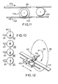
- Fig. 11 shows a third preferred embodiment of the present invention where the endless belt is replaced by a first rack 98 of solid construction and a second rack 100 also of solid construction coupled together by a transfer roller 102.
- the first rack 98 bears upon a first portion of a first diameter of a modified differential wheel 104 and the second rack 100 bears upon a second portion of a second diameter of the modified differential wheel 104.
- the modified differential wheel 104 corresponds in essence to the differential wheel 18 of Figs. 1, 2 and 4 and corresponds to the toothed or geared differential wheel 56 of Fig. 5.
- the racks may be toothed in which case the modified differential wheel 104 is substantially identical with the differential gear wheel 56 of Fig. 5.
- the transfer roller 102 which may also be toothed, ensures that as the first rack 98 is moved as indicated by a seventh arrow 106 so equal and opposite motion is transferred and imparted to the second rack 100 as indicated by an eighth arrow 108.
- the daisy wheel 68 is affixed to rotate co-axially with the modified differential wheel 104.
- Fig. 12 shows a fourth preferred embodiment of the invention wherein a modified carriage 110 is driven along the line of printing by any one of several methods known in the art and where a roller 112 rolls along a flat platform 114 to rotate a shaft 116 which in turn imparts rotation as indicated by a seventh arrow 118 to the daisy wheel 68 shown in phantom outline.
- the roller 112 may be a gear wheel and the flat platform 114 can be a toothed rack.
- the diameter of the roller 112 can be chosen to impart the required rotation to the daisy wheel 68 by direct coupling to the shaft 116 whereon the roller 112 is mounted, or alternatively a gear box arrangement can be provided to transform the angular movement of the roller 112 into an angular rate of movement appropriate for the daisy wheel 68.
- the modified carriage 110 can be moved along the line of printing by a rotating leadscrew, by rods, wires and endless loops in any manner known in the art.
- the daisy wheel 68 does not require to be mounted upon the same end of the shaft 116 as the roller 112 is situated and may be positioned otherwise as is shown in Fig. 12 either directly or through a gear box to be rotated by the shaft 116 on the side of the modified carriage 110 closest to the point of view shown in Fig. 12.
- the daisy wheel 68 has been shown comprising thirty two fingers 80 which number has been chosen purely for convenience in illustrative presentation, and it is to be understood that the daisy wheel 68 can comprise as many fingers as is desired to provide the required number of typed characters.
- the daisy wheel is described as comprising one complete set of characters presented beneath the hammer 72 for each complete rotation of the daisy wheel 68.
- This limitation to one character set per revolu- tioh of the daisy wheel is not a necessary part of the present invention. More than one character set with its increasing early printing off-set may be sequentially spaced around the wheel, in which case the "join" between the last typeface character 94 and the first typeface character 84 is the abutment between two sequential complete character sets.
- the carriage 10, 110 must execute a displacement along the line of printing of two letter spaces for each complete revolution of the daisy wheel 68, if three character sets are provided on the daisy wheel 68, the carriage 10, 110 must execute movement of three letter spaces along the line of printing per revolution of the daisy wheel 68, and so on, the carriage 10, 110 moving along the line of printing for each revolution of the daisy wheel 68 an equal number of letter spaces as there are complete sequential character sets upon the daisy wheel.
- a step is assumed to mean a rotation of the daisy wheel sufficient to bring the next typeface 82 around as indicated by the arrow 96 beneath the hammer 72.
- the motor 30 is a stepping motor imparting one typeface displacement or step per step of the motor 30.
- the motor 30 may impart any integral number of steps between successive typeface characters 82 being presented to the hammer 72.
- the daisy wheel 68 is described as being stopped in its rotation prior to operation of the hammer 72.
- the hammer 72 may be operated whilst the daisy wheel 68 is still in continuous motion to achieve the desired printing.
- the motor 30 may equally well be a continuously operating motor and the angular position of the daisy wheel may be monitored by some form of shaft encoder indicating its position.
- Photo detectors may be used to detect particular typeface characters, such as the last typeface character 94 and/or the first typeface character 84.
- Fig. 13 shows a schematic block diagram of a controller usable with any of the embodiments of the present invention.
- a print command source 120 provides ASCII coded characters in parallel binary digit sequence on demand to an ASCII to character code convertor 122 which recognises the incoming ASCII code and changes the ASCII code into a numerically sequential code used to control the diasy wheel 68.
- the different incoming ASCII codes are converted to a sequence of binary numbers where the first typeface character 84 receives the number 000000, the next around typeface character 82 as indicated by the arrow 96 receives the binary number 000001, the yet next around as indicated by the arrow 96 typeface character 82 receives the number 000010, and so on until the last typeface character 94 receives the binary number 111111.
- the output 124 of the code convertor 122 is presented at a first input to a character code buffer 126 which it receives as an input whenever a source strobe 128 from the source 120 is operated.
- the code buffer 126 provides its output 130 as input to a required number of steps calculator 132 whenever a step and hammer control counter 134 activates a call next character line 136 indicating that printing of the previously provided output character 130 from the buffer 126 has been executed.
- the call next character line 136 is also coupled back to the source 120 to indicate to the source 120 that the source must provide a further ASCII character as input to the code convertor 122.
- the control counter 134 provides output 138 operative to cause the hammer assembly 70 to move the hammer 72 when required and further comprises a stepper motor control output 140 operative to administer positional steps to the motor 30.
- Fig. 4 shows a schematic block diagram of the ASCII to character code convertor 122 of Fig. 13.
- the source 120 supplies ASCII code on a source bus 142 as an address input to a read only memory lookup table 144.
- the data output 146 of the lookup table consists in a single binary number for each input address as previously described, the binary numbers having the positional sequence by unit increment indicated.
- each ASCII code is received from the source bus 142 its angular position indicating binary step number is immediately provided as output 146 from the lookup table 144.
- the lookup table output 146 is coupled as input to a first adder 148 which is operative to add to the binary number retrieve a fixed off-set provided by a coding fixed off-set generator 150.
- a first adder 148 which is operative to add to the binary number retrieve a fixed off-set provided by a coding fixed off-set generator 150.
- the output 152 of the first adder 148 is coupled as input to a first subtractor 154 operative to subtract a selectable decoding fixed off-set provided by a decoding fixed off-set generator 156 when it is desired to decode a simply enciphered document.
- the source 120 of the ASCII code may be an electronic keyboard, a data communication circuit, a data processor or a disc or tape reading machine.
- a document can be provided with an off-set "built in” simply by selecting binary numbers to be provided by the generators 150,156 during printing of the document. If during printing a movement as indicated by the arrow 96 is required then the encoding fixed off-set generator 150 is activated and if a movement contrary to that indicated by the arrow 96 is required then the decoding fixed off-set generator 156 is activated, it being understood that the terms encoding and decoding when used in this sense are interchangeable.
- the output code 158 from the first subtractor 154 can be caused to be equivalent to the original unenciphered text by inversely setting one the other or both of the two fixed off-set generators 150,156.
- the output 146 of the lookup table 144 may be taken directly as the output of the first subtractor 154.
- Fig. 15 shows the character code buffer 126 of Fig. 13.
- the output 158 of the first subtractor 154 (or alternatively the output 146 of the lookup table 144) is coupled as input to a latch register 160 strobed by the strobe source line 128 to receive and store the binary representation of the last ASCII code provided by the source 120.
- the output 162 of the latch register 160 is provided as input to a second register strobed by the call next character line 136 from the step and hammer control counter 134 to hold and store the binary number currently presented at output 162 of the latch register 160 when the call next character line 136 is strobed.
- the output 166, indicating the current character code which the daisy wheel is to print, of the second register 164 is coupled as input to the step calculator as is the output 162 of the latch register 160 indicating the binary number code of the next character which is to be printed.
- Fig. 16 shows the required number of steps calculator 132 otherwise shown in Fig. 13.
- the output 166 of the second register 164 is coupled as a current character binary number or code indicating the character on the daisy wheel 68 which is to be printed as input to an arithmetic unit 168.
- the output 162 of the latch register 160 is coupled as a next character indicating code or binary number as a further input to the arithmetic unit 168.
- the arithmetic unit 168 calculates the required number of character printing positions the daisy wheel 68 is required uni-directionally to move in order to bring the next character indicated on the output 162 of the latch register 160 beneath the hammer 72.
- the daisy wheel 68 if the next character has a binary number code greater than the current character binary number code, moves through an entire revolution before proceeding further around to the next character. If sixty four is here taken as the maximum number of characters on the daisy wheel 68 (only by way of example), then the daisy wheel is first required to move through sixty four steps to bring it back with the current character beneath the hammer 72. If A is the binary number representative of the current character printed and B is representative of the binary number code of the next character to be printed, then, having executed sixty four steps, the wheel 68 is obliged to execute a further (B - A) steps. In total therefore the wheel is required to execute (64 + B - A) steps.
- the daisy wheel 68 In executing that movement, with sixty four the maximum number of characters on the daisy wheel 68, the daisy wheel 68 must first move (64 - A) steps to bring the last typeface character 94 beneath the hammer 72. Thereafter the daisy wheel 68 must move a further B steps to bring the next character to be printed beneath the hammer 72. The total number of steps moved under these circumstances is thus (64 - A + B).
- the output 170 of the arithmetic unit 168 is coupled as input to a second adder 172 which also receives input from an additive cumulative off-set generator 174 comprising dials, switches or other input devices and operative to cause a selectable addition to the required number of steps. If no addition is required the output of the additive cumulative off-set generator 174 is set to zero.
- the second adder 172 provides output 176 coupled as input to a second subtractor which in turn receives a further input from a subtractive cumulative off-set generator 180 which provides a number to be subtracted from the output 176 of the second adder 172.
- the second subtractor 178 provides output 182 coupled with input to the step and hammer control counter 134 of Fig. 13.
- a cumulative off-set is applied to the daisy wheel whereby the printed character moves around the daisy wheel by an acu- mulative amount which increases or decreases on each occasion of printing by selectable predetermined amounts chosen by operation of the additive cumulative off-set generator 174 and subtractive cumulative off-set generator 180.
- a selected input is provided via the generators 174,180 to provide a document not readily readable.
- the inverse off-set is applied via the generators 174,180 to provide legible output.
- a combination of the fixed off-set generators 150,156 and the cumulative off-set generators 174,180 can be used to generate a document which requiring to be deciphered by stages and at no point indicating a form whereat deciphering is complete save when the proper deciphering keys or inputs have been provided to all of the generators 150, 156,174,180.
- the daisy wheel 68 is provided with a space character whereat the hammer 72 is operative.
- the daisy wheel 68 in the present invention employs an active space character on the daisy wheel which, when struck by the hammer, leaves a negligible impression upon the paper but is nonetheless an active hammer operating position on the daisy wheel like any other.
- the active space character on the daisy wheel ensures that during enciphering of any text the beginning and ends of words are concealed.
- the space character becomes substituted for a letter and letters in turn become substituted for the space character.
- the text therefore is broken up into blocks not readily recognisable as individual words.
- the output 170 of the arithmetic unit 168 may be coupled directly in place of the output 182 of the second subtractor 178 and the cumulative generators 174, 180 and the second adders and subtractors 172, 178 omitted.
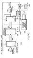
- Fig. 17 shows the step and hammer control counter 134 of Fig. 13.
- the output 182 of the second subtractor 178 is coupled as input to a step number storage register 184 which receives and stores its input whenever the call next character line 136 indicates that the character previously provided has been printed.
- the output 186 of the step number storage register 184 is coupled as a first input to a numerical comparator 188.
- Output 190 from a counter 192 is coupled as a second input to the numerical comparator 188.
- the output 190 of the counter 192 is indicative of the state of count of the counter 192.
- the counter 192 is reset to a all zeroes state whenever the call next character line 136 indicates that printing of the previously provided character has been completed.
- a clock source 194 clocks both the counter 192 and a stepper motor sequencer 196.
- the sequencer 196 provides the stepper motor control output 140 shown in Fig. 13 operative to provide drive to a plurality of windings in sequence in a manner well known in the art to cause the stepper motor 30 to step uni-directionally through a sequence of predetermined positions.
- the sequencer 196 will include a counter which will be initialised whenever optical or other detectors detect that the daisy wheel 68 is in a predetermined position and driver transistors driven via decoders from the counter operative to drive windings in the stepper motor 30.
- the clock source 194 causes the output 190 of the counter 192 to increment.
- the step number storage register 184 receives the required number of steps from the output 182 of the second subtractor 178 and presents them as input 186 to the numerical comparator 188.
- the counter 192 is simultaneously reset to a zero count and the numerical comparator 188 compares the output 190 of the counter with the output 186 of the step number storage register 184.
- the stepper motor 30 moves the daisy wheel 68 round by one position and the output 190 of the counter 192 increments.
- the numerical comparator 188 provides output 198 indicative of the counter 192 output 190 having achieved the required number of steps, the counter -192 is stopped, the clock source 194 is stopped and a first timer 200 is activated.
- First timer 200 allows the daisy wheel 68 properly to come to a halt whilst provided the hammer enable output 138 to the hammer assembly 70 causing the hammer 72 to fly towards the selected character typeface 82 on the daisy wheel 68.
- a second timer 202 provides a second timing operation operative to allow the hammer 72 to strike the daisy wheel 68 and then retreat back into the hammer assembly 70.
- a signal is provided as previously described on the call next character line 136 to present fresh characters throughout the apparatus shown in Fig. 13 to be printed.
- the apparatus in Fig. 17 shows just one example of the manner in which the hammer and the daisy wheel may be operated. It is not strictly necessary that the motor 30 be a stepper motor.
- the motor 30 may be a D.C. motor continuously run and the position of the daisy wheel 68 can be monitored using photo cells and other sensors.
- the hammer can be operated "on the fly” and the counter 192 can be incremented on each detection of a fresh character having passed before the hammer.
- the present invention is not restricted to use of a daisy wheel and any form of type bearing wheel or endless band can be used in place of the daisy wheel.
Landscapes
- Character Spaces And Line Spaces In Printers (AREA)
Claims (23)
Applications Claiming Priority (2)
| Application Number | Priority Date | Filing Date | Title |
|---|---|---|---|
| GB8529523A GB2183548B (en) | 1985-11-30 | 1985-11-30 | Printing apparatus |
| GB8529523 | 1985-11-30 |
Publications (3)
| Publication Number | Publication Date |
|---|---|
| EP0225710A2 EP0225710A2 (fr) | 1987-06-16 |
| EP0225710A3 EP0225710A3 (en) | 1988-03-02 |
| EP0225710B1 true EP0225710B1 (fr) | 1990-03-21 |
Family
ID=10589044
Family Applications (1)
| Application Number | Title | Priority Date | Filing Date |
|---|---|---|---|
| EP86308242A Expired EP0225710B1 (fr) | 1985-11-30 | 1986-10-23 | Appareil d'impression |
Country Status (5)
| Country | Link |
|---|---|
| US (1) | US4770551A (fr) |
| EP (1) | EP0225710B1 (fr) |
| JP (1) | JPS62132648A (fr) |
| DE (1) | DE3669684D1 (fr) |
| GB (2) | GB2183548B (fr) |
Families Citing this family (4)
| Publication number | Priority date | Publication date | Assignee | Title |
|---|---|---|---|---|
| JPH063597B2 (ja) * | 1985-08-20 | 1994-01-12 | 俊明 渡辺 | ワ−ドプロセツサ |
| US6485207B1 (en) | 2001-03-07 | 2002-11-26 | Eugene David Allen | Printer assembly providing tension for idler pulley |
| US7337733B2 (en) * | 2005-06-09 | 2008-03-04 | Gary W. Clem, Inc. | Distance measuring device for planter |
| JP2018207755A (ja) * | 2017-06-09 | 2018-12-27 | ファナック株式会社 | モータ |
Family Cites Families (14)
| Publication number | Priority date | Publication date | Assignee | Title |
|---|---|---|---|---|
| US644165A (en) * | 1898-11-21 | 1900-02-27 | William A Freret Jr | Cryptographic type-writing machine. |
| US2571427A (en) * | 1945-11-19 | 1951-10-16 | Myron J Drachman | Differential mechanism |
| NL129819C (fr) * | 1963-12-06 | |||
| US3356199A (en) * | 1966-02-23 | 1967-12-05 | Friden Inc | Printer having type disk rotatable in a plane parallel to the printing line |
| US3371766A (en) * | 1966-07-18 | 1968-03-05 | Internat Telephone & Telegraph | Printing apparatus |
| FR2085581B1 (fr) * | 1970-01-29 | 1973-06-08 | Honeywell Inf Systems | |
| GB1300519A (en) * | 1971-10-14 | 1972-12-20 | Creed & Company | Traversing drive arrangement for a serial printer |
| US3858509A (en) * | 1972-07-10 | 1975-01-07 | Xerox Corp | Control logic for print wheel and hammer of high speed printing apparatus |
| US3926061A (en) * | 1974-10-02 | 1975-12-16 | Hewlett Packard Co | Differential drive rotating disc impact printer |
| US4149809A (en) * | 1978-01-27 | 1979-04-17 | Scm Corporation | Typewriter spiral disc printer |
| JPS5541204A (en) * | 1978-09-18 | 1980-03-24 | Ricoh Co Ltd | Carriage drive gear for printer |
| JPS58107379A (ja) * | 1981-12-21 | 1983-06-27 | Citizen Watch Co Ltd | プリンタの活字輪駆動装置 |
| JPS5983663A (ja) * | 1982-09-30 | 1984-05-15 | ジエフリ−・ピ−・ステイン | プリンタ |
| EP0134258B1 (fr) * | 1983-08-02 | 1986-11-26 | Ibm Deutschland Gmbh | Dispositif de contrôle du temps de vol de marteaux d'impression dans une imprimante à percussion |
-
1985
- 1985-11-30 GB GB8529523A patent/GB2183548B/en not_active Expired - Lifetime
-
1986
- 1986-10-10 US US06/917,782 patent/US4770551A/en not_active Expired - Fee Related
- 1986-10-23 DE DE8686308242T patent/DE3669684D1/de not_active Expired - Lifetime
- 1986-10-23 EP EP86308242A patent/EP0225710B1/fr not_active Expired
- 1986-11-22 JP JP61279522A patent/JPS62132648A/ja active Pending
-
1989
- 1989-12-13 GB GB8928123A patent/GB2226278B/en not_active Expired - Fee Related
Also Published As
| Publication number | Publication date |
|---|---|
| GB2183548B (en) | 1990-06-13 |
| GB2183548A (en) | 1987-06-10 |
| GB2226278B (en) | 1990-10-03 |
| GB8529523D0 (en) | 1986-01-08 |
| EP0225710A2 (fr) | 1987-06-16 |
| EP0225710A3 (en) | 1988-03-02 |
| DE3669684D1 (de) | 1990-04-26 |
| GB8928123D0 (en) | 1990-02-14 |
| GB2226278A (en) | 1990-06-27 |
| US4770551A (en) | 1988-09-13 |
| JPS62132648A (ja) | 1987-06-15 |
Similar Documents
| Publication | Publication Date | Title |
|---|---|---|
| US2926602A (en) | Automatic printer | |
| US3168182A (en) | Type wheel shifting and impacting means in high speed printers | |
| US3844395A (en) | Text display control for data printer | |
| US3908809A (en) | High speed printer | |
| US4388005A (en) | Method and apparatus for printing partially overlapping characters | |
| EP0227251B1 (fr) | Appareil de transport pour une tête d'imprimante | |
| US3876053A (en) | Serial printing device | |
| US3888340A (en) | Variable pitch tapeless format control system for line printers | |
| US3157115A (en) | Printing mechanism | |
| US4311398A (en) | Printer for producing uniformly spaced characters | |
| GB1207507A (en) | Improvements in or relating to teleprinters and the like | |
| US3482511A (en) | Printing arrangement with tabulated printing cylinder | |
| US4770551A (en) | Printing apparatus for enciphering/deciphering text | |
| SU803854A3 (ru) | Устройство дл выборочного печа-ТАНи | |
| US4044880A (en) | High speed wheel printer and method of operation | |
| US3724631A (en) | Printer with helically arranged type divided into axially offset group | |
| US4305674A (en) | Lateral position control means for data printer heads | |
| US3310147A (en) | Wheel striking data printer | |
| US3420164A (en) | Cyclically operable printing and proportional spacing apparatus | |
| US3253539A (en) | Driving and supporting means for high speed printing drum | |
| US3857471A (en) | Tapeless paper motion control system providing sensing circuits to govern motor incrementing | |
| JPH0313075B2 (fr) | ||
| US3291042A (en) | High speed printing mechanism | |
| US3665850A (en) | Selective belt printing apparatus for printing a line at a time | |
| IE42322B1 (en) | Serial printer |
Legal Events
| Date | Code | Title | Description |
|---|---|---|---|
| PUAI | Public reference made under article 153(3) epc to a published international application that has entered the european phase |
Free format text: ORIGINAL CODE: 0009012 |
|
| 17P | Request for examination filed |
Effective date: 19861030 |
|
| AK | Designated contracting states |
Kind code of ref document: A2 Designated state(s): BE DE FR IT NL SE |
|
| RAP1 | Party data changed (applicant data changed or rights of an application transferred) |
Owner name: UNISYS CORPORATION |
|
| PUAL | Search report despatched |
Free format text: ORIGINAL CODE: 0009013 |
|
| AK | Designated contracting states |
Kind code of ref document: A3 Designated state(s): BE DE FR IT NL SE |
|
| 17Q | First examination report despatched |
Effective date: 19890512 |
|
| GRAA | (expected) grant |
Free format text: ORIGINAL CODE: 0009210 |
|
| AK | Designated contracting states |
Kind code of ref document: B1 Designated state(s): BE DE FR IT NL SE |
|
| ET | Fr: translation filed | ||
| REF | Corresponds to: |
Ref document number: 3669684 Country of ref document: DE Date of ref document: 19900426 |
|
| ITF | It: translation for a ep patent filed | ||
| PLBE | No opposition filed within time limit |
Free format text: ORIGINAL CODE: 0009261 |
|
| STAA | Information on the status of an ep patent application or granted ep patent |
Free format text: STATUS: NO OPPOSITION FILED WITHIN TIME LIMIT |
|
| 26N | No opposition filed | ||
| PGFP | Annual fee paid to national office [announced via postgrant information from national office to epo] |
Ref country code: SE Payment date: 19910930 Year of fee payment: 6 |
|
| PGFP | Annual fee paid to national office [announced via postgrant information from national office to epo] |
Ref country code: FR Payment date: 19911021 Year of fee payment: 6 |
|
| ITTA | It: last paid annual fee | ||
| PGFP | Annual fee paid to national office [announced via postgrant information from national office to epo] |
Ref country code: NL Payment date: 19911031 Year of fee payment: 6 |
|
| PGFP | Annual fee paid to national office [announced via postgrant information from national office to epo] |
Ref country code: BE Payment date: 19911113 Year of fee payment: 6 |
|
| PG25 | Lapsed in a contracting state [announced via postgrant information from national office to epo] |
Ref country code: SE Effective date: 19921024 |
|
| PG25 | Lapsed in a contracting state [announced via postgrant information from national office to epo] |
Ref country code: BE Effective date: 19921031 |
|
| BERE | Be: lapsed |
Owner name: UNISYS CORP. Effective date: 19921031 |
|
| PG25 | Lapsed in a contracting state [announced via postgrant information from national office to epo] |
Ref country code: NL Effective date: 19930501 |
|
| NLV4 | Nl: lapsed or anulled due to non-payment of the annual fee | ||
| PG25 | Lapsed in a contracting state [announced via postgrant information from national office to epo] |
Ref country code: FR Effective date: 19930630 |
|
| REG | Reference to a national code |
Ref country code: FR Ref legal event code: ST |
|
| PGFP | Annual fee paid to national office [announced via postgrant information from national office to epo] |
Ref country code: DE Payment date: 19931026 Year of fee payment: 8 |
|
| EUG | Se: european patent has lapsed |
Ref document number: 86308242.6 Effective date: 19930510 |
|
| PG25 | Lapsed in a contracting state [announced via postgrant information from national office to epo] |
Ref country code: DE Effective date: 19950701 |
|
| PG25 | Lapsed in a contracting state [announced via postgrant information from national office to epo] |
Ref country code: IT Free format text: LAPSE BECAUSE OF NON-PAYMENT OF DUE FEES;WARNING: LAPSES OF ITALIAN PATENTS WITH EFFECTIVE DATE BEFORE 2007 MAY HAVE OCCURRED AT ANY TIME BEFORE 2007. THE CORRECT EFFECTIVE DATE MAY BE DIFFERENT FROM THE ONE RECORDED. Effective date: 20051023 |