EP0225740A1 - Structure de support à barres flexibles de l'enveloppe cylindrique de coeur d'un réacteur nucléaire à eau sous pression - Google Patents
Structure de support à barres flexibles de l'enveloppe cylindrique de coeur d'un réacteur nucléaire à eau sous pression Download PDFInfo
- Publication number
- EP0225740A1 EP0225740A1 EP86308834A EP86308834A EP0225740A1 EP 0225740 A1 EP0225740 A1 EP 0225740A1 EP 86308834 A EP86308834 A EP 86308834A EP 86308834 A EP86308834 A EP 86308834A EP 0225740 A1 EP0225740 A1 EP 0225740A1
- Authority
- EP
- European Patent Office
- Prior art keywords
- type
- top plate
- vertex
- plate
- plates
- Prior art date
- Legal status (The legal status is an assumption and is not a legal conclusion. Google has not performed a legal analysis and makes no representation as to the accuracy of the status listed.)
- Granted
Links
Images


Classifications
-
- G—PHYSICS
- G21—NUCLEAR PHYSICS; NUCLEAR ENGINEERING
- G21C—NUCLEAR REACTORS
- G21C3/00—Reactor fuel elements and their assemblies; Selection of substances for use as reactor fuel elements
- G21C3/38—Fuel units consisting of a single fuel element in a supporting sleeve or in another supporting element
-
- G—PHYSICS
- G21—NUCLEAR PHYSICS; NUCLEAR ENGINEERING
- G21C—NUCLEAR REACTORS
- G21C7/00—Control of nuclear reaction
- G21C7/06—Control of nuclear reaction by application of neutron-absorbing material, i.e. material with absorption cross-section very much in excess of reflection cross-section
- G21C7/08—Control of nuclear reaction by application of neutron-absorbing material, i.e. material with absorption cross-section very much in excess of reflection cross-section by displacement of solid control elements, e.g. control rods
- G21C7/10—Construction of control elements
- G21C7/117—Clusters of control rods; Spider construction
-
- Y—GENERAL TAGGING OF NEW TECHNOLOGICAL DEVELOPMENTS; GENERAL TAGGING OF CROSS-SECTIONAL TECHNOLOGIES SPANNING OVER SEVERAL SECTIONS OF THE IPC; TECHNICAL SUBJECTS COVERED BY FORMER USPC CROSS-REFERENCE ART COLLECTIONS [XRACs] AND DIGESTS
- Y02—TECHNOLOGIES OR APPLICATIONS FOR MITIGATION OR ADAPTATION AGAINST CLIMATE CHANGE
- Y02E—REDUCTION OF GREENHOUSE GAS [GHG] EMISSIONS, RELATED TO ENERGY GENERATION, TRANSMISSION OR DISTRIBUTION
- Y02E30/00—Energy generation of nuclear origin
- Y02E30/30—Nuclear fission reactors
Definitions
- This invention relates to pressurized water reactors and, more particularly, to a flexible support for the rod guides positioned within the inner barrel assembly of a pressurized water reactor.
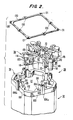
- Certain advanced designs of nuclear reactors incorporate at successively higher, axially aligned elevations within the reactor vessel, a lower barrel assembly, an inner barrel assembly, and a calandria, each of generally cylindrical configuration, and an upper closure dome.
- the lower barrel assembly may be conventional, having mounted therein, in parallel axial relationship, a plurality of fuel rod assemblies which are supported at the lower and upper ends thereof, respectively, by corresponding lower and upper core plates.
- Within the inner barrel assembly there is provided a large number of rod guides disposed in closely spaced relationship, in an array extending substantially throughout the cross-sectional area of the inner barrel assembly.
- the rod guides are of first and second types, respectively housing therewithin reactor control rod clusters (RCC) and water displacer rodlet clusters (WDRC); these clusters, as received within their respectively associated guides, generally are aligned with the fuel rod assemblies.
- the calandria includes a lower calandria plate and an upper calandria plate.
- the rod guides are secured in position at the lower and upper ends thereof respectively, to the upper core plate and the lower calandria plate.
- Within the calandria and extending between the lower and upper plates thereof is mounted a plurality of calandria tubes in parallel axial relationship and respectively aligned with the rod guides.
- a number of flow holes are provided in remaining portions of the lower calandria plate, intermediate the calandria tubes, through which passes the reactor core outlet flow as it exits from its passage through the inner barrel assembly.
- the calandria tubes are joined to corresponding flow shrouds which extend to a predetermined elevation within the dome, and which in turn are connected to corresponding head extensions which pass through the structural wall of the dome and carry, on their free ends at the exterior of and vertically above the dome, corresponding adjustment mechanisms.
- the adjustment mechanisms have corresponding drive shafts which extend through the respective head extensions, flow shrouds, and calandria tubes and are connected to the respectively associated clusters of RCC rods and WDRC rods, and serve to adjust their elevational positions within the inner barrel assembly and, particularly, the level to which same are lowered into the lower barrel assembly and thus into association with the fuel rod assemblies therein, thereby to control the activity within the core.
- a critical design criterion of such reactors is to minimize wear of the rodlets at interfaces between the individual rodlets of a given cluster and known support plate structures within the rod guide through which the rodlets pass for support, and thus to reduce or eliminate the factors which produce wear, such as flow induced vibration and associated vibration of reactor internal structures.
- Because of the relatively dense packing of the rod guides within the inner barrel assembly it is critical to maintain substantially uniform distribution of the outlet flow from the reactor core, and an axial direction of that flow through the upper barrel assembly. Even if a uniform, axial flow of the core outlet is achieved, the effects of differential pressure and temperature across the array of rod guides, or an individual rod guide, can produce significant reaction loads at the support points, or support connections, for the rod guides.
- split pin connections of conventional types are inappropriate for use as the supporting connections for the top ends of the rod guides since they would wear rapidly, with the result that the top ends of the rod guides would become loose.
- Rod guides having such loose top end connections are unacceptable because of the rapid rate of wear of the rodlets which would result.
- Other known mounting devices as well are inappropriate.
- leaf springs cannot be used to support all of the rod guides because sufficient space is not available within the inner barrel assembly to provide leaf springs of the proper size for the large number of rod guides which are present, even if high strength material is used for the leaf springs.
- both the RCC and the WDRC rod clusters should be removable without requiring that the guides be disassembled.
- This requirement imposes a severe space limitation in view of the dense packing of the guides and their associated rod clusters within the inner barrel assembly.
- over 2,800 rods are mounted in 185 clusters, the latter being received within a corresponding 185 guides.
- the space limitation is further compounded by the requirement that unimpeded flow holes must be provided in the calandria plates for the core outlet flow.
- the presence of the support members should not require any increase in the height of the vessel. From a maintenance standpoint, the support members should be visible for inspection and replaceable without undue effort. Additionally, the assembly load of the calandria must be less than its dead weight and must be accomplished without access to the support region. This avoids having to apply force to the calandria before installing the vessel head.
- the present invention resides in a flexible support structure for the upper ends of first and second pluralities of rod guides of respective first (32) and second (28) different types disposed as corresponding, interleaved first and second matrices thereof in parallel axial relationship within an inner barrel assembly (24) of a pressurized water reactor vessel (10) for receiving therein respective, corresponding first (34) and second (30) different types of rod clusters, the inner barrel assembly (24) occupying a central portion of the vessel (10) and being of a vertical height extending from a first plate (19) of a lower elevation to a second plate (52) of a higher elevation, each of said rod guides (32, 28) being of elongated configuration and of an axial length corresponding substantially to the vertical height of said inner barrel assembly (24) and said first (32) and second (28) pluralities of rod guides being disposed in parallel axial relationship in an array of interleaved, respective first and second matrices with the bottom ends thereof affixed to said first plate (19) and the top ends thereof
- the flexible linkages are generally of square configuration, each being attached at four places to its respective WDRC guide top plate. Further, each such flexible linkage is attached to each of the four contiguous, surrounding, RCC guide top plates, at four corresponding, individual connections or attachment points. Thus, each WDRC guide is attached, or concatenated, laterally to the four surrounding RCC rod guides via the flexible linkage. This concatenated assembly of linkages creates a stiff structure between the guides in a plane perpendicular to the axis of the rod guides.
- the guides are essentially bound together laterally; however, the linkages in the out-of-plane direction, i.e., axially, are flexible and thus accommodate relative axial motion between guides to permit bowing of adjacent guides.
- This capability of flexibility in one plane must be provided to compensate for local differences in height of adjacent guides due to differential thermal expansion and bowing due to pressure differential across the guide.
- the flexible linkages in accordance with the invention will be understood to be flexible in a direction parallel to the axis of the rod guide, but rigid in a plane perpendicular to the axis of the rod guide.
- the assemblage of linkages in the concatenated arrangement as well are rigid in the plane perpendicular to the parallel axes of the array of rod guides. Absent this flexibility of the linkages, the linkages would be overstressed and would fail. Further, the flexible linkages are recessed into the top plates to prevent damage during assembly.
- the pin stops are located on the top of the WDRC guides and mate with openings provided therefor in the associated four, adjacent RCC guides.
- the pin stops serve three purposes. First, during assembly of the guides, the pin stops provide rough positioning of adjacent rod guides prior to attachment of the square flexes. Secondly, the pin stops limit the amount of deflection possible along the axis of the flexible linkage, and thereby prevent excessive stress of any individual element due to an unanticipated and transient conditions. Finally, the pin stops provide an ultimate load capacity for very large loads. Essentially, the pin stops have a greater load capability than that of the WDRC guide itself. Proper selection of the material for the pin stop enables the attachment between adjacent guides to have the same or greater lateral load capacity than the rod guide enclosures.
- a further major advantage of the combined flexible linkage support and leaf spring frictional support is that wear or gap size between the calandria and the rod guides can be virtually ignored due to the continuing ability of the leaf springs to react lateral force components on the rod guides, even in the event of wear of the calandria extensions, and thus to suppress top end lateral motion and correspondingly prevent any increase in the excitation of the rodlets. This assures that rodlet wear does not increase, despite the potential of slippage due to inadvertent wear of the rod guide support, the need for significant gaps to permit assembly, and resultant increased tolerances between adjoining parts. Further, the concatenated interconnections of the flexible linkages distribute loads between adjacent extensions.
- a pressurized water reactor 10 comprises a vessel 12 of generally conventional configuration including an upper dome 12a, cylindrical sidewalls 12b, and a bottom closure 12c comprising the base of the reactor 10.
- the lower barrel assembly 16 comprises a generally cylindrical sidewall 17 affixed at its lower and upper ends to respective lower and upper core plates 18 and 19.
- Fuel rod assemblies 20 are positioned in generally vertically oriented, parallel axial relationship within the lower barrel assembly 16.
- a radiation reflection shield 21 is mounted interiorly of the. cylindrical sidewalls 17, in conventional fashion.
- the inner barrel assembly 24 includes a cylindrical sidewall 26 within which are positioned a plurality of rod guides in closely spaced, parallel axial relationship; for simplicity of illustration, only two such rod guides are shown in Fig. 1, namely rod guide 28 housing a cluster of radiation control rods 30 (RCC) and a rod guide 32 housing a cluster of water displacement rods 34 (WDRC).
- Mounting means 36 and 37 are provided at the respective upper and lower ends of the rod guide 28 and, correspondingly, mounting means 38 and 39 are provided at the respective upper and lower ends of the rod guide 32, and lower end mounting means 37 and 39 mounting the respective rod guides 28 and 32 to the upper core plate 19, and the upper mounting means 36 and 38 mounting the respective rod guides 28 and 32 to a calandria assembly 50.
- the calandria assembly 50 includes a lower calandria plate 52, an upper calandria plate 54, and a-plurality of parallel axial calandria tubes 56 which are positioned in alignment with corresponding apertures in the lower and upper calandria plates 52 and 54 and to which the calandria tubes 56 are mounted at their respective, opposite ends.
- Calandria extensions 58 project downwardly from the calandria tubes 56 and connect to corresponding mounting means 36 for the upper ends, or tops, of the RCC rod guides 28.
- the upper and mounting means 38 associated with the WDRC rod guides 32 are interconnected by the flexible linkage to the mounting means 36 of the RCC rod guides 28.
- the calandria extensions 58 are associated only with the RCC rod guides 28 and not with the WDRC rod guides 32 but serve, through the flexible linkages, to provide both stiff lateral as well as resilient axial support to compensate for relative differences in positioning the rod guide top plates 35 and 38, without overstressing the flexible linkages 130.
- Control rod cluster (RCC) displacement mechanisms 64 and water displacement rod cluster (WDRC) displacement mechanisms 66 are associated with the respective head extensions 62, flow shrouds 60 and calandria tubes 56 which, in turn, are respectively associated with the respective clusters of radiation control rods 30 and water displacement rods 34.
- the RCC and WDRC displacement mechanisms 64 and 66 connect through corresponding lines to the respective clusters of radiation control rods and water displacement rods 30 and 34, to control the respective vertical positions thereof and, particularly, to selectively lower same through corresponding openings (not shown) provided therefore in the upper core plate 19 into surrounding relationship with respectively associated fuel rod assemblies 20.
- the clusters 30 and 34 have an extent of travel represented by the distance D designated in Fig. 1.
- Fig. 2 comprises a perspective, exploded and partially broken away view of rod guides and respectively associated top plates, in conjunction with a flexible linkage in accordance with a first embodiment of the present invention.
- Fig. 3 comprising a top plan view taken along the line 3-3 in Fig. 1 of an exemplary assemblage of a top plate of a first (WDRC) type, as interdigitized with associated top plates of a second (RCC) type disposed in surrounding, mating relationship therewith and, further, as interconnected by a flexible linkage, all in accordance with the aforesaid first embodiment of the invention.
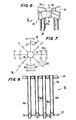
- Fig. 4 and Fig. 5 comprise elevational, cross-sectional views taken along the lines 4-4 and 5-5, respectively, in Fig. 3.
- the rod guide 32 for the WDRC rod cluster 34 and the rod guide 28 for the RCC rod cluster 30, as best seen in Fig. 2, have first and second, different configurations, and have respectively associated therewith top plates 38 and 36 corresponding to the respective mounting means 38 and 36 diagrammatically illustrated in Fig. 1.
- Each of the rod guides 28 and 30 is formed of sheet metal and each of the respective top plates 36 and 38 is machined to achieve the configurations as illustrated.
- the peripheries of the top plates 36 and 38 generally correspond to the peripheries of the respective rod guides 28 and 30, as viewed in cross-section taken in a plane transverse to the vertical axes thereof and thus parallel to the plane of Fig. 3.
- top plates 36 and 38 furthermore have interior channels 70 and 72, respectively, the profiles or boundaries of which correspond to the configuration, again in cross-section, of the corresponding RCC rod clusters 30 and WDRC rod clusters 34, the latter being illustrated in simplified schematic form in Figs. 6 and 7, respectively.
- the RCC rod cluster 80 shown in a simplified perspective view, includes a spider 82 comprising a pair of orthogonally related cross arms 82a and 82b interconnected by a central hub 83, a plurality of RCC rodlets or rods 84 depending from the arms 82a and 82b. Particularly, each of the arms 82a and 82b carries four (4) such rods 84.
- the interior channel 70 of the top plate 36 has a profile corresponding to the RCC rod cluster 30, permitting the latter to be lowered axially through the channel 70 thereof under control of the control rod displacement mechanism 64 (Fig. 1) which connects through drive line 86 to the central hub 83 of the spider 82 of the RCC rod cluster 30.
- the interior channel 72 of the WDRC top plate 38 likewise has a profile corresponding to the periphery, again in cross-section, of the WDRC rod cluster 34 (Fig. 1), the latter being shown in a simplified schematic plan view in Fig. 7.
- the WDRC rod cluster 34 similarly includes a spider 90 having a plurality of radially extending arms 92 connected to a central hub 93; further, alternate ones of the arms 92 include transverse cross arms 92a. A plurality of WDRC rods 94 then are appropriately connected to the arms 92 and 92a and depend therefrom in parallel axial relationship.
- the respective rod guides 28 and 30 and the associated top plates 36 and 38 are configured so as to permit relatively dense packaging thereof and, more particularly, the assemblage thereof as interdigitized matrices.
- the top plate 38 of the WDRC rod guides 30 is surrounded by a symmetrical, associated sub-array of four RCC top plates 36; further, each of the RCC top plates 36 in turn is configured to engage an associated sub-array of four WDRC top plates 38.
- the WDRC top plate 38 is of a generally annular configuration with a generally square periphery and includes four (4) major arms 100, each pair of two (2) adjacent arms 100 extending in perpendicular relationship and the totality of four (4) such pairs defining four (4) major exterior vertices, or corners.
- a diagonal minor arm 102 spans each such vertex and integrally interconnects the pair of associated, adjacent major arms 100.
- Inwardly transverse, or lateral, extensions 104 are formed at intermediate positions along the length of each of the major arms 100 displaced from the opposite ends thereof, and integrally join a central, link connection vertical stub 106.
- An outwardly transverse, or lateral wedge-fit extension 106a is formed on the stub 106, extending beyond the outer sidewall surface, or periphery, of the major arm 100.
- a link connection threaded bore 107 is formed in each vertical stub 106.
- the RCC top plate 36 (best seen in Fig. 3) includes a corresponding plurality of four (4) equiangularly displaced major arms 110, the interior peripheral edges of each pair of adjacent arms 110 defining an interior vertex which receives therein a corresponding exterior vertex, or corner, of the top plate 38, as defined by a pair of adjacent major arms 100 thereof.
- the top plate 36 further includes a diagonal minor arm 112 extending across the geometrical interior vertex defined by the major arms 110, the exterior vertical surface of the arm 112 corresponding to the interior vertical surface of the diagonal minor arm 102 of the top plate 38.
- Transverse, or lateral extensions 114 extend symmetrically from both sides of the major arms 110, each extension 114 corresponding in size and configuration to the corresponding lateral extension 104 of a top plate 38 associated with the corresponding arm 100.
- the transverse lateral extensions 114 on the respective peripheral edges of a pair of adjacent major arms 110 which define a given interior vertex are continuous with the diagonal minor arm 112, and furthermore the extensions 114 and the included diagonal minor arm 112 have a common planar upper surface, corresponding to the planar upper surface of the major arms 110, but are foreshortened in vertical height relative to that of the major arms 110 such that the lower surfaces thereof define an undercut interior peripheral region, or channel, 118.
- each major arm 110 furthermore includes a wedge-fit extension 116 generally aligned with the major axis of the corresponding major arm 110.
- a stop pin bore 115 is formed in each of the transverse Lateral extensions 114 of each arm 110 in a position so as to be aligned with the stop pin bore 105 in the corresponding inward lateral extension 104 of a corresponding arm 100 when the top plates 36 and 38 are assembled, as in Fig. 3.
- a link connection threaded bore 117 is formed in the integral juncture 110' of adjacent major arms 110 surrounding the interior channel 70 and defining the interior vertex.
- a groove 120 further is formed in the associated transverse extensions 114 and the included diagonal minor arm 112, extending along the respectively associated peripheral edges of the associated pair of adjacent major arms 110 and communicating with a counter bore 121 which is coaxial with the threaded bore 117.
- each diagonal minor arm 102 of the top plate 38 is received within the corresponding diagonal portion of the channel 118 defined by the diagonal minor arm 112 and the integral juncture 110' of an adjacent pair of major arms 110, the diagonal minor arm 112 thus being superposed on diagonal minor arm 102.
- the transverse lateral extensions 114 are superposed on the respective midside, inward lateral extensions 104 of a given major arm 100 of the top plate 38.
- a flexible linkage 130 is received within the channels 120 of the group of top plates surrounding a given top plate 38, which then is bolted in position.
- bolts 132 are received through the apertures 131 in the corners, or vertices, of the linkage 130 and securely threaded into the corresponding, threaded bores 117 and, further, bolts 134 are received through the apertures 133 in the side arms of the linkage 130 and securely threaded into the corresponding threaded bores 107 in the link connector vertical stubs 106.
- Respective matrices of top plates 36 and 38 thus are interdigitized by virtue of the respective structural components defining the mating, interior and exterior vertices thereof and including the channels 118 and the superposed lateral, or transverse, extensions 114 and 104.
- the top plates are laterally interlocked (i.e., in a plane perpendicular to the axis of the assembly 24) by the flexible linkages 130 in a two dimensional, concatenated relationship in which each of the top plates 38 is linked rigidly in the lateral direction to four respectively surrounding top plates 36 -- and, in turn, each of the top plates 36 is laterally interlocked at its four interior vertices to associated exterior vertices of four top plates 38 which are interdigitized therewith.
- the outer edges, or the periphery, of the array necessarily will be defined by one or more peripheral edges of either one or the other of the top plates 36 and 38 -- typically, the top plates 36.
- FIG. 8 is an enlarged view of the portion of a lower calandria plate 52 and of a broken-away portion of the upper calandria plate 54, illustrating more clearly the association of the calandria tubes 56 and the calandria plates 52 and 54.
- the calandria tubes 56a which are connected at their lower ends to corresponding calandria extensions 58 are associated with the RCC rod clusters and the associated top plates 36.
- Calandria tubes 56b are associated with the WDRC rod clusters and the corresponding top plates 38.
- flow holes 59 Provided in the lower calandria plates 52, intermediate the various calandria tubes 56, are flow holes 59 through which the core output flow, exiting upwardly from the inn2r barrel assembly 24, proceeds through the calandria assembly 50.
- Corresponding flow holes are provided in the upper calandria 54.
- Fig. 9 is a top plan view of a portion of the lower calandria plate 52, illustrating (in solid cross-section) the assemblage of calandria tubes 56a and 56b associated with the array of top plates 36 and 38 shown in Fig. 3.
- Fig. 10 is a cross-sectional view illustrating the connection of a top plate 36 to the calandria bottom plate 52 by a calandria extension 58.
- the calandria extension 58 of circular cross-section, is received within the corresponding circular cross-sectional channel 70 of an RCC top plate 36, thus establishing lateral stability of the RCC top plate 36; each top plate 36 receives a corresponding calandria extension 58 in its channel 70.
- the RCC top plates 36 are supported directly, and the interdigitized and concatenated top plates 38 thus are supported through the top plates 36, against lateral movement by the plurality of calandria extensions 58 and ultimately.by the lower calandria plate 52.
- Figs. 9 and 10 taken concurrently, illustrate leaf springs 140 which resiliently load the top surfaces of the top plates 36 of the RCC rod guides 28, and which generate sufficient lateral frictional force such that fluctuating steady state loads applied to the guides do not cause slippage; the springs 140 also compensate for effects of differential thermal expansion and minimize adverse effects of resulting forces due to such thermal expansions. More particularly, the leaf springs 140 are attached to the lower surface of the lower calandria plate 52 by suitable screws 142; as seen better in Fig.
- the leaf springs 140 comprise two parallel pairs 140-1, 140-2 and 140-3, 140-4, for a total of four (4) springs, the first pair of springs 140-1 and 140-2 being aligned with the second pair of springs 140-3 and 140-4 and thus displaced from one another by 130° about the generally circular cross-section cf the RCC calandria tube 56a.
- the leaf springs 140 are rotated by 90° for successive RCC calandria tubes 56a of a given row, the leaf springs 140 for the respective, column-related calandria tubes 56a of successive, adjacent parallel rows being offset by 90°. From Fig.
- the two related pairs of leaf springs 140 extending from a given calandria extension 58 associated with a given top plate 36, at their outer free ends, engage the corresponding end extremities of the upper surfaces of the adjacent, aligned major arms 100 of the aligned and next adjacent RCC top plates 36 (only one of which is shown) at corresponding positions close to the outer, free ends thereof.
- each top plate 36 is engaged by a symmetrically loaded force by corresponding leaf springs at the outer extremities of the aligned, or 180° displaced, major arms 100 so as to maintain a symmetrical or balanced loading force thereon.
- the flexible rod guide support structure of the invention As outlined briefly above, the adverse environmental conditions (e.g., vibration, and both axial and lateral displacement forces) which exist within the inner barrel assembly 24 and the manner in which the flexible rod guide support structure of the present invention accommodates these conditions and satisfies those requirements, as now may be better appreciated, will be discussed, again with reference to Fig. 1. Further, as before noted, the flexible support structure of the invention must, itself, not introduce sources of vibration and most significantly must not be susceptible to excessive wear which, over time, would cause the mounting assembly to loosen and eventually permit vibrations to ensue.
- the adverse environmental conditions e.g., vibration, and both axial and lateral displacement forces
- the concatenated and interdigitized matrices of the RCC top plates 36 and WDRC top plates 38 effectively present a single, relatively stiff structure of mutually, or interdependently, supported top plates at the interface of the inner barrel assembly 24 and the lower calandria plate 52, which nevertheless permits a limited extent of relative motion between the rod guides 28 and 32 by out-of-plane bending of the flexible linkages 130.
- the flexible support structure of the invention furthermore facilitates assembling the rod guides with the calandria extensions 58 -- which assembly, as before noted, is accomplished by having the.RCC top plates 36 receive the calandria extensions 58 within the respective cylindrical internal channels 70 therein.
- the stop pins 125 prevent excessive loading of any of the flexible linkages 130 and ensure that loads from the WDRC rod guides 30 are transmitted through the concatenated and interdigitized RCC top plates 36 into the calandria bottom plate 52.
- the stop pins 25 serve a further function in providing rough positioning of the interdigitized top plates 36 and 38 prior to attachment thereto of the flexible linkages 130.
- the leaf springs 140 serve to react normal operational fluctuating loads laterally, by the frictional forces generated by their engagement with the top surfaces of the RCC top plates 36.
- the leaf springs may be of the type known as 17x17 fuel assembly springs, which are typically employed in conjunction with the fuel rod assemblies 20 in the lower barrel assembly 16.
- the leaf springs 140 may be designed to react nominally a force of 388 lbs. at each RCC guide top plate 36, assuming a coefficient of 0.3 without slippage. More specifically, the nominal force applied to each RCC top plate 35 is 1,294 lbs. with a range of 918 lbs. to 1,528 lbs.
- the lateral force can be nominally as great as 388 lbs. before any movement of a given top plate 36 would occur. Differential lateral forces across the array thus may be compensated for and reacted to independently by the corresponding leaf springs 140.
- the concatenated design particularly precludes impact wear from occurring between the rod guide top plates 36 and 38 and the calandria extensions 58. To the extent that such wear does occur, and particularly relative to the calandria extensions 58, the extent and effect of such wear is believed not significant relative to rod guide alignment or the structural capability of the extensions 58 to react to seismic loads.
- the concatenated relationship of the interdigitized matrices of the array affords the further significant benefits of distributing force effects via the flexible linkages and compensating for differential axial expansion and lateral forces acting on the array, throughout the entirely of the interdigitized rod guide top plates 36 and 38, and thus minimizing wear potential with respect to any given calandria extension 58 and its respectively associated top plate 36, and of the interface between any given rod guide and its associated rodlet cluster.
- Fig. 10 only minimal axial space is required to accommodate the array of top plates 36 and 38 and the flexible linkages 130 therein, along with the leaf springs 140; this enables use of the flexible rod guide support structure of the invention without requiring any modification of the vessel 10 to accommodate an axially elongated inner barrel assembly 24.
- the flexible support structure of the invention does not interfere with the required free passage of core outlet flow through the openings 59 provided therefor in the lower calandria plate 52 (i.e., at which the support structure of the invention presents an interface, as before noted).
- each square linkage 130 comprises effectively a unitary assemblage of four individual flexible support linkages of two perpendicular arms each, namely the pair of adjacent linkage arms extending from and including a vertex having a screw hole 131, and through and including the enlarged portions containing the screw holes 133.
- four (4) separate linkages so configured could be employed in the alternative to a unitary linkage 130 as shown; while this would simplify manufacture, it would increase the number of parts and connectors required for assembly.
- the cross-section of the arms of the linkage 130 may be varied to achieve the desired stiffness.
- the arms of each individual linkage, or the corresponding arms of a unitary assemblage may have an L-shape (i.e., of equal length arms) or other configuration, in accordance with the configurations of the associated top plates and the related connection positions thereon.
- Fig. 11 is a schematic and somewhat simplified top plan view of an alternative arrangement of an RCC top plate 36' and a WDRC top plate 38' having an associated flexible linkage 130'
- Fig. 12 comprising an elevational cross-sectional view along the lines 12-12 in Fig. 11.
- the flexible linkage 130' is of star-shaped configuration and is connected to the respective top plates 36' and 38' in somewhat of a reverse orientation of parts, relative to the embodiment of Figs. 2-10.
- the adjacent major arms 100' of the WDRC top plate 38' again form an exterior vertex crossed by a diagonal minor arm 102' which is received by a channel 118' such that a diagonal minor arm 112' of the RCC top support 36' is superposed in part on the diagonal minor arm 102' of the WDRC top plate 38' in interdigitized relationship.
- the diagonal arm 102' in this instance is extended vertically relatively to the height of the major arms 100', in a manner somewhat analogous to the vertical stub extension 106 of the top plate 38 as seen in Fig. 2.
- a groove 120' extends downwardly through the top surface of the major arms 110' and a star-shaped flexible linkage 130' then is received within the grooves.
- the central aperture 133' of the linkage 130' thus is disposed in alignment with the link connection threaded bore 107' in the diagonal minor arm 102', and the corner apertures 131' of the linkage 130' are disposed in alignment with the respective link connection threaded bores 117', in this instance formed in the extremities of the major arms 110' of the RCC top plate 36'.
- corresponding bolts are not shown in Fig. 11, Fig. 12 illustrates a bolt 134' connecting the center aperture 133' of the flexible linkage 130' to the diagonal minor arm 102' of the WDRC top plate 38'. Similar bolts of course would connect the corner apertures of the linkage 130' to the extremities of the major arms 110' of the RCC top plate 36.
- each exterior vertex of the WDRC top plate 38' is received in mating engagement within an interior vertex of the RCC top plate 36', as in the first embodiment of the invention, and the same are concatenated by a flexible linkage interconnecting the major arms of one thereof with the major arms of the other, the link connection positions being reversed effectively in the embodiment of Figs. 11 and 12, relatively to those of the first embodiment.
Landscapes
- Physics & Mathematics (AREA)
- Engineering & Computer Science (AREA)
- Plasma & Fusion (AREA)
- General Engineering & Computer Science (AREA)
- High Energy & Nuclear Physics (AREA)
- Chemical & Material Sciences (AREA)
- Chemical Kinetics & Catalysis (AREA)
- Monitoring And Testing Of Nuclear Reactors (AREA)
- Physical Or Chemical Processes And Apparatus (AREA)
Applications Claiming Priority (2)
| Application Number | Priority Date | Filing Date | Title |
|---|---|---|---|
| US79822085A | 1985-11-14 | 1985-11-14 | |
| US798220 | 1985-11-14 |
Publications (2)
| Publication Number | Publication Date |
|---|---|
| EP0225740A1 true EP0225740A1 (fr) | 1987-06-16 |
| EP0225740B1 EP0225740B1 (fr) | 1990-05-09 |
Family
ID=25172833
Family Applications (1)
| Application Number | Title | Priority Date | Filing Date |
|---|---|---|---|
| EP86308834A Expired - Lifetime EP0225740B1 (fr) | 1985-11-14 | 1986-11-12 | Structure de support à barres flexibles de l'enveloppe cylindrique de coeur d'un réacteur nucléaire à eau sous pression |
Country Status (4)
| Country | Link |
|---|---|
| EP (1) | EP0225740B1 (fr) |
| JP (1) | JPS62119494A (fr) |
| KR (1) | KR870005400A (fr) |
| ES (1) | ES2015881B3 (fr) |
Cited By (3)
| Publication number | Priority date | Publication date | Assignee | Title |
|---|---|---|---|---|
| EP0229705A3 (en) * | 1986-01-09 | 1988-07-27 | Westinghouse Electric Corporation | Rod guide support structure of the inner barrel assembly of a pressurized water reactor |
| EP0266592A3 (en) * | 1986-11-03 | 1989-03-01 | Westinghouse Electric Corporation | Simplified, flexible top end support for cantilever-mounted rod guides of a pressurized water reactor |
| CN109036595A (zh) * | 2018-08-01 | 2018-12-18 | 中广核研究院有限公司 | 用于反应堆容器的多向滑动支承装置 |
Citations (4)
| Publication number | Priority date | Publication date | Assignee | Title |
|---|---|---|---|---|
| EP0054790A2 (fr) * | 1980-12-16 | 1982-06-30 | Westinghouse Electric Corporation | Procédé de contrôle d'un réacteur à dérive spectrale |
| EP0128091A1 (fr) * | 1983-06-03 | 1984-12-12 | Framatome | Dispositif de guidage des grappes de contrôle de réacteurs nucléaires |
| EP0151082A2 (fr) * | 1984-01-30 | 1985-08-07 | Framatome | Dispositif de pilotage du coeur d'un réacteur nucléaire |
| EP0195686A1 (fr) * | 1985-03-22 | 1986-09-24 | Westinghouse Electric Corporation | Réacteur nucléaire |
-
1986
- 1986-11-12 ES ES86308834T patent/ES2015881B3/es not_active Expired - Lifetime
- 1986-11-12 EP EP86308834A patent/EP0225740B1/fr not_active Expired - Lifetime
- 1986-11-14 JP JP61272746A patent/JPS62119494A/ja active Pending
- 1986-11-14 KR KR860009643A patent/KR870005400A/ko not_active Withdrawn
Patent Citations (4)
| Publication number | Priority date | Publication date | Assignee | Title |
|---|---|---|---|---|
| EP0054790A2 (fr) * | 1980-12-16 | 1982-06-30 | Westinghouse Electric Corporation | Procédé de contrôle d'un réacteur à dérive spectrale |
| EP0128091A1 (fr) * | 1983-06-03 | 1984-12-12 | Framatome | Dispositif de guidage des grappes de contrôle de réacteurs nucléaires |
| EP0151082A2 (fr) * | 1984-01-30 | 1985-08-07 | Framatome | Dispositif de pilotage du coeur d'un réacteur nucléaire |
| EP0195686A1 (fr) * | 1985-03-22 | 1986-09-24 | Westinghouse Electric Corporation | Réacteur nucléaire |
Cited By (4)
| Publication number | Priority date | Publication date | Assignee | Title |
|---|---|---|---|---|
| EP0229705A3 (en) * | 1986-01-09 | 1988-07-27 | Westinghouse Electric Corporation | Rod guide support structure of the inner barrel assembly of a pressurized water reactor |
| EP0266592A3 (en) * | 1986-11-03 | 1989-03-01 | Westinghouse Electric Corporation | Simplified, flexible top end support for cantilever-mounted rod guides of a pressurized water reactor |
| CN109036595A (zh) * | 2018-08-01 | 2018-12-18 | 中广核研究院有限公司 | 用于反应堆容器的多向滑动支承装置 |
| CN109036595B (zh) * | 2018-08-01 | 2023-10-31 | 中广核研究院有限公司 | 用于反应堆容器的多向滑动支承装置 |
Also Published As
| Publication number | Publication date |
|---|---|
| ES2015881B3 (es) | 1990-09-16 |
| JPS62119494A (ja) | 1987-05-30 |
| KR870005400A (ko) | 1987-06-08 |
| EP0225740B1 (fr) | 1990-05-09 |
Similar Documents
| Publication | Publication Date | Title |
|---|---|---|
| US4687628A (en) | Flexible rod guide support structure for inner barrel assembly of pressurized water reactor | |
| EP1736996B1 (fr) | Assemblage de combustible nucléaire muni de grilles d'espacement avec maintien des barreaux de combustible en position excentrée | |
| US4675154A (en) | Nuclear fuel assembly with large coolant conducting tube | |
| KR100338912B1 (ko) | 원자로내에서연료봉을지지하기위한격자구조체 | |
| US4357298A (en) | Nuclear fuel assembly space arrangement | |
| US6606369B1 (en) | Nuclear reactor with improved grid | |
| US4585616A (en) | Nuclear fuel spacer grid with improved outer straps | |
| US4857264A (en) | Frictionally loaded top end supports for cantilever-mounted rod guides of a pressurized water reactor | |
| EP0229705B1 (fr) | Structure de support pour le guidage de barres de contrôle dans l'enveloppe du coeur d'un réacteur à eau pressurisée | |
| JPH03200093A (ja) | 核燃料集合体スペーサとたわみ性の高いループばね | |
| EP0225740B1 (fr) | Structure de support à barres flexibles de l'enveloppe cylindrique de coeur d'un réacteur nucléaire à eau sous pression | |
| US4587704A (en) | Method of mounting a continuous loop spring on a nuclear fuel spacer | |
| EP0222373B1 (fr) | Support supérieur pour les guides de barres de déplacement d'eau d'un réacteurnucliaire à eau pressurisée | |
| US4793965A (en) | Simplified, flexible top end support for cantilever-mounted rod guides of a pressurized water reactor | |
| CN86107837A (zh) | 用于核反应堆的带有定心和防振定位装置的棒束导向装置 | |
| JPH04254793A (ja) | 炉心隔壁装置 | |
| US5133926A (en) | Extended burnup top nozzle for a nuclear fuel assembly | |
| US4622204A (en) | Spacer grid for nuclear reactor fuel assembly | |
| US4624829A (en) | Nuclear fuel assembly channel spring and stop assembly and method of using same | |
| EP1710810A1 (fr) | Grille d'espacement concue pour maintenir chaque barreau de combustible en quatre points d'appui | |
| EP0656632B1 (fr) | Assemblage combustible avec dispositifs de support des barreaux de combustible | |
| US4752441A (en) | Modular former for inner barrel assembly of pressurized water reactor | |
| EP0363710A2 (fr) | Colonne de support et tube-guide combiné appliqués dans un réacteur nucléaire | |
| GB2104712A (en) | Nuclear reactors | |
| GB2105095A (en) | Nuclear reactors |
Legal Events
| Date | Code | Title | Description |
|---|---|---|---|
| PUAI | Public reference made under article 153(3) epc to a published international application that has entered the european phase |
Free format text: ORIGINAL CODE: 0009012 |
|
| AK | Designated contracting states |
Kind code of ref document: A1 Designated state(s): BE CH ES FR GB IT LI |
|
| 17P | Request for examination filed |
Effective date: 19871216 |
|
| 17Q | First examination report despatched |
Effective date: 19890524 |
|
| ITF | It: translation for a ep patent filed | ||
| GRAA | (expected) grant |
Free format text: ORIGINAL CODE: 0009210 |
|
| AK | Designated contracting states |
Kind code of ref document: B1 Designated state(s): BE CH ES FR GB IT LI |
|
| ET | Fr: translation filed | ||
| PGFP | Annual fee paid to national office [announced via postgrant information from national office to epo] |
Ref country code: BE Payment date: 19900719 Year of fee payment: 5 |
|
| PGFP | Annual fee paid to national office [announced via postgrant information from national office to epo] |
Ref country code: CH Payment date: 19901011 Year of fee payment: 5 |
|
| PGFP | Annual fee paid to national office [announced via postgrant information from national office to epo] |
Ref country code: ES Payment date: 19901105 Year of fee payment: 5 |
|
| ITTA | It: last paid annual fee | ||
| PLBE | No opposition filed within time limit |
Free format text: ORIGINAL CODE: 0009261 |
|
| STAA | Information on the status of an ep patent application or granted ep patent |
Free format text: STATUS: NO OPPOSITION FILED WITHIN TIME LIMIT |
|
| 26N | No opposition filed | ||
| PG25 | Lapsed in a contracting state [announced via postgrant information from national office to epo] |
Ref country code: ES Free format text: LAPSE BECAUSE OF NON-PAYMENT OF DUE FEES Effective date: 19911113 |
|
| PGFP | Annual fee paid to national office [announced via postgrant information from national office to epo] |
Ref country code: FR Payment date: 19911122 Year of fee payment: 6 |
|
| PG25 | Lapsed in a contracting state [announced via postgrant information from national office to epo] |
Ref country code: LI Effective date: 19911130 Ref country code: CH Effective date: 19911130 Ref country code: BE Effective date: 19911130 |
|
| BERE | Be: lapsed |
Owner name: WESTINGHOUSE ELECTRIC CORP. Effective date: 19911130 |
|
| REG | Reference to a national code |
Ref country code: CH Ref legal event code: PL |
|
| PG25 | Lapsed in a contracting state [announced via postgrant information from national office to epo] |
Ref country code: FR Effective date: 19930730 |
|
| REG | Reference to a national code |
Ref country code: FR Ref legal event code: ST |
|
| PGFP | Annual fee paid to national office [announced via postgrant information from national office to epo] |
Ref country code: GB Payment date: 19991004 Year of fee payment: 14 |
|
| PG25 | Lapsed in a contracting state [announced via postgrant information from national office to epo] |
Ref country code: GB Free format text: LAPSE BECAUSE OF NON-PAYMENT OF DUE FEES Effective date: 20001112 |
|
| REG | Reference to a national code |
Ref country code: ES Ref legal event code: FD2A Effective date: 20010503 |
|
| GBPC | Gb: european patent ceased through non-payment of renewal fee |
Effective date: 20001112 |
|
| PG25 | Lapsed in a contracting state [announced via postgrant information from national office to epo] |
Ref country code: IT Free format text: LAPSE BECAUSE OF NON-PAYMENT OF DUE FEES;WARNING: LAPSES OF ITALIAN PATENTS WITH EFFECTIVE DATE BEFORE 2007 MAY HAVE OCCURRED AT ANY TIME BEFORE 2007. THE CORRECT EFFECTIVE DATE MAY BE DIFFERENT FROM THE ONE RECORDED. Effective date: 20051112 |