EP0225768A2 - Baukörper - Google Patents
Baukörper Download PDFInfo
- Publication number
- EP0225768A2 EP0225768A2 EP86309277A EP86309277A EP0225768A2 EP 0225768 A2 EP0225768 A2 EP 0225768A2 EP 86309277 A EP86309277 A EP 86309277A EP 86309277 A EP86309277 A EP 86309277A EP 0225768 A2 EP0225768 A2 EP 0225768A2
- Authority
- EP
- European Patent Office
- Prior art keywords
- structural member
- channel
- elongate structural
- web
- drainage
- Prior art date
- Legal status (The legal status is an assumption and is not a legal conclusion. Google has not performed a legal analysis and makes no representation as to the accuracy of the status listed.)
- Granted
Links
- 238000000034 method Methods 0.000 claims description 12
- 238000003825 pressing Methods 0.000 claims description 5
- 238000004080 punching Methods 0.000 claims description 4
- 238000005266 casting Methods 0.000 claims description 2
- 238000005096 rolling process Methods 0.000 claims description 2
- 229910000831 Steel Inorganic materials 0.000 abstract description 5
- 239000010959 steel Substances 0.000 abstract description 5
- 238000005260 corrosion Methods 0.000 abstract description 3
- 230000007797 corrosion Effects 0.000 abstract description 3
- 239000011248 coating agent Substances 0.000 description 2
- 238000000576 coating method Methods 0.000 description 2
- 238000010276 construction Methods 0.000 description 2
- HCHKCACWOHOZIP-UHFFFAOYSA-N Zinc Chemical compound [Zn] HCHKCACWOHOZIP-UHFFFAOYSA-N 0.000 description 1
- 239000010426 asphalt Substances 0.000 description 1
- 230000001680 brushing effect Effects 0.000 description 1
- 238000005253 cladding Methods 0.000 description 1
- 238000009413 insulation Methods 0.000 description 1
- 230000007774 longterm Effects 0.000 description 1
- 239000000463 material Substances 0.000 description 1
- 239000003973 paint Substances 0.000 description 1
- 239000011253 protective coating Substances 0.000 description 1
- 239000007921 spray Substances 0.000 description 1
- 238000009433 steel framing Methods 0.000 description 1
- 230000009974 thixotropic effect Effects 0.000 description 1
- 239000011701 zinc Substances 0.000 description 1
- 229910052725 zinc Inorganic materials 0.000 description 1
Images
Classifications
-
- E—FIXED CONSTRUCTIONS
- E04—BUILDING
- E04C—STRUCTURAL ELEMENTS; BUILDING MATERIALS
- E04C3/00—Structural elongated elements designed for load-supporting
- E04C3/02—Joists; Girders, trusses, or trusslike structures, e.g. prefabricated; Lintels; Transoms; Braces
- E04C3/04—Joists; Girders, trusses, or trusslike structures, e.g. prefabricated; Lintels; Transoms; Braces of metal
- E04C3/06—Joists; Girders, trusses, or trusslike structures, e.g. prefabricated; Lintels; Transoms; Braces of metal with substantially solid, i.e. unapertured, web
- E04C3/07—Joists; Girders, trusses, or trusslike structures, e.g. prefabricated; Lintels; Transoms; Braces of metal with substantially solid, i.e. unapertured, web at least partly of bent or otherwise deformed strip- or sheet-like material
-
- E—FIXED CONSTRUCTIONS
- E04—BUILDING
- E04C—STRUCTURAL ELEMENTS; BUILDING MATERIALS
- E04C3/00—Structural elongated elements designed for load-supporting
- E04C3/02—Joists; Girders, trusses, or trusslike structures, e.g. prefabricated; Lintels; Transoms; Braces
- E04C3/04—Joists; Girders, trusses, or trusslike structures, e.g. prefabricated; Lintels; Transoms; Braces of metal
- E04C2003/0404—Joists; Girders, trusses, or trusslike structures, e.g. prefabricated; Lintels; Transoms; Braces of metal beams, girders, or joists characterised by cross-sectional aspects
- E04C2003/0408—Joists; Girders, trusses, or trusslike structures, e.g. prefabricated; Lintels; Transoms; Braces of metal beams, girders, or joists characterised by cross-sectional aspects characterised by assembly or the cross-section
- E04C2003/0421—Joists; Girders, trusses, or trusslike structures, e.g. prefabricated; Lintels; Transoms; Braces of metal beams, girders, or joists characterised by cross-sectional aspects characterised by assembly or the cross-section comprising one single unitary part
-
- E—FIXED CONSTRUCTIONS
- E04—BUILDING
- E04C—STRUCTURAL ELEMENTS; BUILDING MATERIALS
- E04C3/00—Structural elongated elements designed for load-supporting
- E04C3/02—Joists; Girders, trusses, or trusslike structures, e.g. prefabricated; Lintels; Transoms; Braces
- E04C3/04—Joists; Girders, trusses, or trusslike structures, e.g. prefabricated; Lintels; Transoms; Braces of metal
- E04C2003/0404—Joists; Girders, trusses, or trusslike structures, e.g. prefabricated; Lintels; Transoms; Braces of metal beams, girders, or joists characterised by cross-sectional aspects
- E04C2003/0426—Joists; Girders, trusses, or trusslike structures, e.g. prefabricated; Lintels; Transoms; Braces of metal beams, girders, or joists characterised by cross-sectional aspects characterised by material distribution in cross section
- E04C2003/0434—Joists; Girders, trusses, or trusslike structures, e.g. prefabricated; Lintels; Transoms; Braces of metal beams, girders, or joists characterised by cross-sectional aspects characterised by material distribution in cross section the open cross-section free of enclosed cavities
-
- E—FIXED CONSTRUCTIONS
- E04—BUILDING
- E04C—STRUCTURAL ELEMENTS; BUILDING MATERIALS
- E04C3/00—Structural elongated elements designed for load-supporting
- E04C3/02—Joists; Girders, trusses, or trusslike structures, e.g. prefabricated; Lintels; Transoms; Braces
- E04C3/04—Joists; Girders, trusses, or trusslike structures, e.g. prefabricated; Lintels; Transoms; Braces of metal
- E04C2003/0404—Joists; Girders, trusses, or trusslike structures, e.g. prefabricated; Lintels; Transoms; Braces of metal beams, girders, or joists characterised by cross-sectional aspects
- E04C2003/0443—Joists; Girders, trusses, or trusslike structures, e.g. prefabricated; Lintels; Transoms; Braces of metal beams, girders, or joists characterised by cross-sectional aspects characterised by substantial shape of the cross-section
- E04C2003/0473—U- or C-shaped
Definitions
- This invention relates to structural members, and is more particularly, but not exclusively, concerned with structural members of galvanised steel frames for buildings.
- U.K. Specification No. 2,146,054A describes a steel frame for this purpose which incorporates a channel-section bottom member having two ribs formed in the bottom of the channel and extending parallel to the sides of the channel. These ribs serve to support upright members having their ends extending into the channel in such a manner that there is a gap between the end of the upright member and the bottom of the channel which allows moisture accumulating within the channel to drain freely along the length of the channel.
- an elongate structural member of channel section having a central web and two parallel flanges extending along opposite edges of the web and projecting to one side of the web, at least one rib being provided in the central web and projecting into the channel formed by the member, wherein at least one drainage hole is provided in the member so as to enable drainage of moisture accumulating within the channel at a point intermediate the two ends of the member.
- Such an arrangement provides a significant improvement in terms of resistance to corrosion over the long term since it enables moisture to drain off not only from the ends of the member, but also from one or more points intermediate the two ends.
- drainage holes are provided at equally spaced locations along the length of the member.
- the drainage holes may be provided in at least one of the flanges. If provided in both flanges, the holes may alternate between the two flanges along the length of the member. Furthermore each hole may be formed so as to extend both through a flange and through the adjacent portion of the central web.
- each rib extends longitudinally of the member, and at least one discontinuity is formed in the rib(s) at a point intermediate the two ends of the member so as to enable drainage of moisture at this point between the portions of the web on opposite sides of the discontinuity.
- the discontinuity preferably comprises simply a portion of the web which is flush with the portions of the web on the two sides of the discontinuity.
- discontinuities are provided in the or each rib at equally spaced locations along the length of the member. If two ribs are provided in the central web extending longitudinally of the member, the discontinuities in the two ribs may be staggered in relation to one another along the length of the member.
- the invention also provides a method of forming such a structural member utilising separate rolling and punching operations, and preferably also a pressing operation.
- the invention also provides a method of forming such a structural member comprising a casting operation.
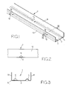
- the channel-section structural member 1 comprises a central web 2 having parallel ribs 4 and 6 extending along its length and two parallel flanges 8 and 10 extending along opposite edges of the web 2 and projecting in the same direction as the ribs 4 and 6.
- Drainage holes 12 are formed in the flange 10 at 300mm spaced centres along the length of the member 1. These holes 12 overlap the bottom of the flange 10 and extend into the edge of the web 2. No drainage holes are provided in the flange 8.
- discontinuities 14 are provided in the rib 4 at 300mm spaced centres along the length of the member 1
- discontinuities 16 are provided in the rib 6 at 300mm spaced centres along the length of the member 1.
- the discontinuities 16 in the rib 6 correspond in position to the drainage holes 12 along the length of the member 1, whereas the discontinuities 14 in the rib 4 are staggered in relation to the discontinuities 16 in the rib 6,being offset by 150mm longitudinally in relation to the discontinuities 16 and the drainage holes 12.
- the drainage holes 12 and the discontinuities 14 and 16 in combination enable free drainage of moisture accumulating in the channel at points intermediate the two ends of the member 1, in addition to the drainage at the two ends of the channel.
- the above-described structural member is intended primarily for use as the bottom plate of a frame, although it may also be used for studs, noggins, top plates and bracing plates of wall panels, as well as for struts, ties and bracing plates of roof trusses. Generally the member will have longer flanges when used for the bottom chord of a roof truss.
- the member 1 may be formed by two possible methods, namely by a pressing method and by a roll-forming method.
- a blank in the form of a flat sheet of a predetermined fixed length and an overall width of 150 mm, for example, is placed in a press brake machine with a maximum tool length of 3658 mm, for example, and the two ribs are pressed in separate operations.
- hole punching to a predetermined pattern is carried out.
- Two right-angled holes are then produced to form the required channel section, and finally the section formed is passed through another tool which produces the flattened discontinuities at predetermined centres one rib at a time.
- a narrow coil of galvanised steel (for example about 140 mm in width) is fed through a roll former which performs the various operations to produce the final section. If required hole punching can be performed prior to use of the roll former.
- the ribs may be formed either continuously followed by a further operation to form the flattened discontinuities in the ribs, or intermittently with the discontinuities being left between adjacent rib portions.
- the section is then passed through a series of stages which gradually form the sides of the channel. Finally the fully formed section is cut to a predetermined length.
- a protective coating is preferably applied to the member after forming, either by brushing or by spray application.
- the coating is preferably a cold applied bitumen heavy duty coating which is applied in the form of a thixotropic paint.
Landscapes
- Engineering & Computer Science (AREA)
- Architecture (AREA)
- Civil Engineering (AREA)
- Structural Engineering (AREA)
- Rod-Shaped Construction Members (AREA)
- Laminated Bodies (AREA)
- Building Environments (AREA)
- Roof Covering Using Slabs Or Stiff Sheets (AREA)
- Hydrogenated Pyridines (AREA)
Priority Applications (1)
| Application Number | Priority Date | Filing Date | Title |
|---|---|---|---|
| AT86309277T ATE53882T1 (de) | 1985-12-11 | 1986-11-27 | Baukoerper. |
Applications Claiming Priority (2)
| Application Number | Priority Date | Filing Date | Title |
|---|---|---|---|
| GB8530535 | 1985-12-11 | ||
| GB858530535A GB8530535D0 (en) | 1985-12-11 | 1985-12-11 | Structural members |
Publications (3)
| Publication Number | Publication Date |
|---|---|
| EP0225768A2 true EP0225768A2 (de) | 1987-06-16 |
| EP0225768A3 EP0225768A3 (en) | 1987-12-02 |
| EP0225768B1 EP0225768B1 (de) | 1990-05-02 |
Family
ID=10589605
Family Applications (1)
| Application Number | Title | Priority Date | Filing Date |
|---|---|---|---|
| EP86309277A Expired - Lifetime EP0225768B1 (de) | 1985-12-11 | 1986-11-27 | Baukörper |
Country Status (4)
| Country | Link |
|---|---|
| EP (1) | EP0225768B1 (de) |
| AT (1) | ATE53882T1 (de) |
| DE (1) | DE3670873D1 (de) |
| GB (1) | GB8530535D0 (de) |
Cited By (1)
| Publication number | Priority date | Publication date | Assignee | Title |
|---|---|---|---|---|
| ES2068097A2 (es) * | 1992-05-29 | 1995-04-01 | Gavalda Antonio Herms | "mejoras introducidas en la patente de invencion n p9201278 por viga de refuerzo perfeccionada y su procedimiento de colocacion" |
Family Cites Families (8)
| Publication number | Priority date | Publication date | Assignee | Title |
|---|---|---|---|---|
| US1545168A (en) * | 1924-12-04 | 1925-07-07 | Bethlehem Steel Corp | Beam and its method of manufacture |
| US4011704A (en) * | 1971-08-30 | 1977-03-15 | Wheeling-Pittsburgh Steel Corporation | Non-ghosting building construction |
| FR2239914A5 (en) * | 1973-07-31 | 1975-02-28 | Vincens Rene | Composite structure built of standard elements - is for permanent or portable structures and decorative elements |
| AU517480B2 (en) * | 1978-04-04 | 1981-08-06 | Winstone Limited | U-beam |
| GB8307933D0 (en) * | 1983-03-23 | 1983-04-27 | Precision Metal Forming Ltd | Structural frames |
| GB2143558B (en) * | 1983-06-28 | 1987-10-28 | Pearce & Cutler Limited | Curtain walling system |
| NZ211265A (en) * | 1984-02-28 | 1989-01-06 | Bruce Capper | Fascia and soffit panels eave assembly |
| US4621470A (en) * | 1984-04-02 | 1986-11-11 | United States Gypsum Company | Runner and area separation wall structure utilizing runner |
-
1985
- 1985-12-11 GB GB858530535A patent/GB8530535D0/en active Pending
-
1986
- 1986-11-27 AT AT86309277T patent/ATE53882T1/de not_active IP Right Cessation
- 1986-11-27 EP EP86309277A patent/EP0225768B1/de not_active Expired - Lifetime
- 1986-11-27 DE DE8686309277T patent/DE3670873D1/de not_active Expired - Fee Related
Cited By (1)
| Publication number | Priority date | Publication date | Assignee | Title |
|---|---|---|---|---|
| ES2068097A2 (es) * | 1992-05-29 | 1995-04-01 | Gavalda Antonio Herms | "mejoras introducidas en la patente de invencion n p9201278 por viga de refuerzo perfeccionada y su procedimiento de colocacion" |
Also Published As
| Publication number | Publication date |
|---|---|
| EP0225768B1 (de) | 1990-05-02 |
| EP0225768A3 (en) | 1987-12-02 |
| GB8530535D0 (en) | 1986-01-22 |
| DE3670873D1 (de) | 1990-06-07 |
| ATE53882T1 (de) | 1990-06-15 |
Similar Documents
| Publication | Publication Date | Title |
|---|---|---|
| US6131362A (en) | Sheet metal beam | |
| US4862667A (en) | Metal structural fastener/stiffener with integral prongs | |
| EP0034332B1 (de) | Bauelement zur Wärmedämmung bei Gebäuden | |
| US8146314B2 (en) | Prefabricated universal structural steel panel and panel system | |
| US3979868A (en) | Composite concrete and steel floor construction | |
| US4078352A (en) | Truss-web connector | |
| US6799406B2 (en) | Bolted metal joist and method of manufacturing the same | |
| US2088781A (en) | Studding structure | |
| US3945168A (en) | Reusable spanner bar | |
| EP0004346A1 (de) | Kastenträger zur Verwendung als Tragteil und solche Kastenträger umfassende Bauwerke | |
| DE69010326T2 (de) | Plattenträgersystem. | |
| US20030167722A1 (en) | Versa-track wall/floor joist assembly and method | |
| US5205098A (en) | Long-span decking panel | |
| CA2366099C (en) | Interlocking truss system | |
| EP2181227B1 (de) | Vorgefertigtes transportables verbundwandelement aus schalungssteinen | |
| US4503652A (en) | Bracing element | |
| US2205725A (en) | Beam structure | |
| EP0225768B1 (de) | Baukörper | |
| US4584815A (en) | Flange hanger | |
| EP0090473A1 (de) | Gebäude, Wandelemente und Profile für dieselben | |
| GB469098A (en) | Improvements relating to light weight floors, roofs, walls, doors and like building constructions | |
| JPH1181551A (ja) | 建築用フレームおよびその構造部材 | |
| US1669095A (en) | Structural unit | |
| EP0822300A2 (de) | Herstellungssystem für die Konstruktion von weitspannigen Dächern mit Blechformpfetten | |
| CH637445A5 (de) | Kuehl- oder tiefkuehlhalle. |
Legal Events
| Date | Code | Title | Description |
|---|---|---|---|
| PUAI | Public reference made under article 153(3) epc to a published international application that has entered the european phase |
Free format text: ORIGINAL CODE: 0009012 |
|
| AK | Designated contracting states |
Kind code of ref document: A2 Designated state(s): AT BE CH DE FR GB LI LU NL |
|
| PUAL | Search report despatched |
Free format text: ORIGINAL CODE: 0009013 |
|
| AK | Designated contracting states |
Kind code of ref document: A3 Designated state(s): AT BE CH DE FR GB LI LU NL |
|
| 17P | Request for examination filed |
Effective date: 19880108 |
|
| 17Q | First examination report despatched |
Effective date: 19880926 |
|
| GRAA | (expected) grant |
Free format text: ORIGINAL CODE: 0009210 |
|
| AK | Designated contracting states |
Kind code of ref document: B1 Designated state(s): AT BE CH DE FR GB LI LU NL |
|
| PG25 | Lapsed in a contracting state [announced via postgrant information from national office to epo] |
Ref country code: LI Effective date: 19900502 Ref country code: CH Effective date: 19900502 Ref country code: AT Effective date: 19900502 |
|
| REF | Corresponds to: |
Ref document number: 53882 Country of ref document: AT Date of ref document: 19900615 Kind code of ref document: T |
|
| REF | Corresponds to: |
Ref document number: 3670873 Country of ref document: DE Date of ref document: 19900607 |
|
| REG | Reference to a national code |
Ref country code: CH Ref legal event code: PL |
|
| ET | Fr: translation filed | ||
| PLBE | No opposition filed within time limit |
Free format text: ORIGINAL CODE: 0009261 |
|
| STAA | Information on the status of an ep patent application or granted ep patent |
Free format text: STATUS: NO OPPOSITION FILED WITHIN TIME LIMIT |
|
| 26N | No opposition filed | ||
| REG | Reference to a national code |
Ref country code: GB Ref legal event code: 732 |
|
| REG | Reference to a national code |
Ref country code: FR Ref legal event code: TP |
|
| NLS | Nl: assignments of ep-patents |
Owner name: BRITISH STEEL PLC TE LONDEN, GROOT-BRITTANNIE. |
|
| EPTA | Lu: last paid annual fee | ||
| PGFP | Annual fee paid to national office [announced via postgrant information from national office to epo] |
Ref country code: FR Payment date: 19981008 Year of fee payment: 13 |
|
| PGFP | Annual fee paid to national office [announced via postgrant information from national office to epo] |
Ref country code: BE Payment date: 19981022 Year of fee payment: 13 |
|
| PGFP | Annual fee paid to national office [announced via postgrant information from national office to epo] |
Ref country code: DE Payment date: 19981027 Year of fee payment: 13 |
|
| PGFP | Annual fee paid to national office [announced via postgrant information from national office to epo] |
Ref country code: NL Payment date: 19981028 Year of fee payment: 13 |
|
| PGFP | Annual fee paid to national office [announced via postgrant information from national office to epo] |
Ref country code: GB Payment date: 19981120 Year of fee payment: 13 |
|
| PG25 | Lapsed in a contracting state [announced via postgrant information from national office to epo] |
Ref country code: LU Free format text: LAPSE BECAUSE OF NON-PAYMENT OF DUE FEES Effective date: 19981127 |
|
| PGFP | Annual fee paid to national office [announced via postgrant information from national office to epo] |
Ref country code: LU Payment date: 19991019 Year of fee payment: 13 |
|
| PG25 | Lapsed in a contracting state [announced via postgrant information from national office to epo] |
Ref country code: GB Free format text: LAPSE BECAUSE OF NON-PAYMENT OF DUE FEES Effective date: 19991127 |
|
| PG25 | Lapsed in a contracting state [announced via postgrant information from national office to epo] |
Ref country code: BE Free format text: LAPSE BECAUSE OF NON-PAYMENT OF DUE FEES Effective date: 19991130 |
|
| BERE | Be: lapsed |
Owner name: BRITISH STEEL P.L.C. Effective date: 19991130 |
|
| PG25 | Lapsed in a contracting state [announced via postgrant information from national office to epo] |
Ref country code: NL Free format text: LAPSE BECAUSE OF NON-PAYMENT OF DUE FEES Effective date: 20000601 |
|
| GBPC | Gb: european patent ceased through non-payment of renewal fee |
Effective date: 19991127 |
|
| PG25 | Lapsed in a contracting state [announced via postgrant information from national office to epo] |
Ref country code: FR Free format text: LAPSE BECAUSE OF NON-PAYMENT OF DUE FEES Effective date: 20000731 |
|
| NLV4 | Nl: lapsed or anulled due to non-payment of the annual fee |
Effective date: 20000601 |
|
| PG25 | Lapsed in a contracting state [announced via postgrant information from national office to epo] |
Ref country code: DE Free format text: LAPSE BECAUSE OF NON-PAYMENT OF DUE FEES Effective date: 20000901 |
|
| REG | Reference to a national code |
Ref country code: FR Ref legal event code: ST |