EP0225806A2 - Support d'outil - Google Patents
Support d'outil Download PDFInfo
- Publication number
- EP0225806A2 EP0225806A2 EP86309613A EP86309613A EP0225806A2 EP 0225806 A2 EP0225806 A2 EP 0225806A2 EP 86309613 A EP86309613 A EP 86309613A EP 86309613 A EP86309613 A EP 86309613A EP 0225806 A2 EP0225806 A2 EP 0225806A2
- Authority
- EP
- European Patent Office
- Prior art keywords
- tool
- tool holder
- stop
- grinding device
- grinding
- Prior art date
- Legal status (The legal status is an assumption and is not a legal conclusion. Google has not performed a legal analysis and makes no representation as to the accuracy of the status listed.)
- Withdrawn
Links
Images


Classifications
-
- B—PERFORMING OPERATIONS; TRANSPORTING
- B24—GRINDING; POLISHING
- B24B—MACHINES, DEVICES, OR PROCESSES FOR GRINDING OR POLISHING; DRESSING OR CONDITIONING OF ABRADING SURFACES; FEEDING OF GRINDING, POLISHING, OR LAPPING AGENTS
- B24B3/00—Sharpening cutting edges, e.g. of tools; Accessories therefor, e.g. for holding the tools
- B24B3/36—Sharpening cutting edges, e.g. of tools; Accessories therefor, e.g. for holding the tools of cutting blades
-
- B—PERFORMING OPERATIONS; TRANSPORTING
- B23—MACHINE TOOLS; METAL-WORKING NOT OTHERWISE PROVIDED FOR
- B23Q—DETAILS, COMPONENTS, OR ACCESSORIES FOR MACHINE TOOLS, e.g. ARRANGEMENTS FOR COPYING OR CONTROLLING; MACHINE TOOLS IN GENERAL CHARACTERISED BY THE CONSTRUCTION OF PARTICULAR DETAILS OR COMPONENTS; COMBINATIONS OR ASSOCIATIONS OF METAL-WORKING MACHINES, NOT DIRECTED TO A PARTICULAR RESULT
- B23Q1/00—Members which are comprised in the general build-up of a form of machine, particularly relatively large fixed members
- B23Q1/25—Movable or adjustable work or tool supports
- B23Q1/44—Movable or adjustable work or tool supports using particular mechanisms
- B23Q1/48—Movable or adjustable work or tool supports using particular mechanisms with sliding pairs and rotating pairs
- B23Q1/4828—Movable or adjustable work or tool supports using particular mechanisms with sliding pairs and rotating pairs a single rotating pair followed parallelly by a single sliding pair
-
- B—PERFORMING OPERATIONS; TRANSPORTING
- B24—GRINDING; POLISHING
- B24B—MACHINES, DEVICES, OR PROCESSES FOR GRINDING OR POLISHING; DRESSING OR CONDITIONING OF ABRADING SURFACES; FEEDING OF GRINDING, POLISHING, OR LAPPING AGENTS
- B24B41/00—Component parts such as frames, beds, carriages, headstocks
- B24B41/06—Work supports, e.g. adjustable steadies
- B24B41/066—Work supports, e.g. adjustable steadies adapted for supporting work in the form of tools, e.g. drills
Definitions
- This invention relates to a tool holder, and particularly, but not exclusively, to a tool holder for use when locating a tool relative to a grinding wheel.
- the angle of the tool relative to the grinding wheel can be accurately adjusted and that the tool can be moved transversely to the wheel to ensure that the bevel ground on the tool is even across the width of the tool.
- a first object of the present invention is to provide a tool holder whereby the relative angle of the tool being held can be adjusted, but which, at the same time, permits the tool holder to be moved, say, across the face of a tool working member, such as a grinding wheel, hereinafter called, for convenience, a grinding wheel.
- a second object of the invention is to provide a tool holder having associated therewith means whereby the actual angle of the tool relative to the grinding wheel can be readily set.
- the invention in its broadest sense, comprises a tool holder having a body, the body being mounted on a member transverse to the axis of the tool when the tool is located therein or thereon, and adapted for movement along this member, tool receiving means whereby the tool to be held can be firmly supported relative to the body and a member extending from the body, which means abut against a stop thereof limiting movement of the tool holder towards the tool working member.
- the member extending from the body be pivotally mounted to the body about an axis parallel to the axis of the transverse member, the arrangement being that the tool holder can be pivotted away from its work position without obstruction, but, when moved to the work position, the member is restrained, thus controlling the angle of the tool holder.
- an adjustment means be provided whereby the angle of the means extending from the body can be readily adjusted.
- I provide means whereby a fixed tool angle can be achieved with the means comprising a plurality of stops mounted adjacent the tool holder, the stops being at different distances from the tool holder so that, when a tool is clamped in the tool holder and abutting a particular stop, then a required angle is obtained.
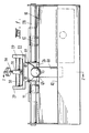
- a tool sharpener 10 having a pair of spaced grinding wheels 11 and 12, which may preferably be coaxial, in which one wheel 11, the coarse wheel, has a slightly larger diameter than the other wheel 12, the fine wheel, whereby a tool 20 may initially have its bevel formed on the larger diameter wheel and may have its edge completed on the smaller diameter wheel.
- the tool holder of the invention has a body 22 having a flat tool receiving surface 25 underneath which there is a downward extension 26 having a support receiving aperture 27 therethrough, the support receiving aperture having its axis parallel to the plane of the flat tool receiving surface and at right angles to the required axis of the tool when located. This can best be seen in Fig. 2.
- This support receiving aperture receives a support rod 28 which has its axis effectively parallel to the axes of the grinding wheel, and the aperture is of such a diameter as to permit the tool body to be able to be freely moved along the rod and rotated relative to the rod.
- lug 29 On either side of the flat tool receiving surface there may be an upwardly directed lug 29 or the like, which lugs are interconnected by a rod 30 parallel to the support rod and, on this rod, there can be pivotally located a tool clamp 31 which can be moved along the rod to be located substantially centrally of a tool located on the receiving surface and abutting one lug.
- the clamp comprises a nose 32 on one side of the rod and a threaded aperture 33 on the other side of the rod, through which aperture a clamp screw 34 passes, the arrangement being such that the clamp screw is brought down into contact with the tool to be held, causing the nose of the clamp to be moved into contact with the tool on the other side of the pivotal axis, so the tool is firmly located on the receiving surface of the body.
- a stop member 40 mounted on the rear surface of the downward extension, is a stop member 40 as best shown in Fig. 2, the mounting being by means of a pivot 41 parallel to the axis of the support arm and this member extends downwardly behind a stop surface or edge 42 which may be formed integrally with part of the body of the machine and which is parallel to the support arm or, alternatively, may be a plate or the like fitted to the body of the machine.
- an adjustment screw 43 Passing through the member 40 and in line with the downward extension from the body 26, there is an adjustment screw 43 which can be used to vary and angle between the member and the body of the tool holder.
- the member 40 is pivotally connected to the downward extension 26 of the tool holder body, it is possible to rotate the tool holder body away from the grinding wheels, so that the angle between the downwardly extending member and the stop member is increased and, during such movement, a tool to be sharpened can readily be located and clamped onto the top of the tool receiving surface.
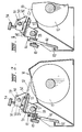
- Fig. 3 illustrates the tool holder of the invention in the grinding position.
- Fig. 4 shows the tool holder pivotted back away from the grinding wheel, allowing a tool to be fitted or removed.
- the tool can readily be removed from contact with the grinding wheel and examined without altering the location of the tool in the clamp.
- the chisel blade will be able to be received on the surface and can be clamped so that one side of the chisel blade abuts one of the lugs 29 and the clamp can be moved along its rod 28 to be effectively central of the blade and then by tightening of the clamp screws 34, so the nose of the clamp and the screw come into contact with the blade, and firmly holds the blade.
- the tool to be sharpened is a plane iron
- the same operation is effected, and it will be seen that, notwithstanding the difference in thickness between the plane iron and the blade, the clamping can be done effectively.
- the tool to be sharpened was a buzzer blade, which is relatively wide
- the required angle for the blade can be achieved by adjustment of the screw member 43 passing through the member extending downwardly and the blade is sharpened, initially, by moving it across the larger diameter coarse, wheel 11 so that the bevel is formed.
- the body When the cutting edge of the blade is to be finished, the body is moved across to adjacent the smaller diameter, fine, wheel 12 and the difference in diameter of the two wheels may be such that the fine wheel only contacts the outer extremity of the blade.
- the screw 43 could be adjusted to vary this angle.
- stop surface or edge 42 could be relieved adjacent the fine wheel so the wheel rather than the stop member limits the movement of the tool holder.
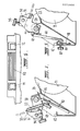
- Fig. 5 illustrates an alternative method of adjustment of the angle of the blade to be sharpened relative to the wheel by providing the stop surface separate from the edge 42 on the body of the machine so that the stop surface can be moved inwardly or outwardly relative to the body of the tool receiving member.
- This may preferably be done by hinging an elongate member 48 running across the width of the tool along its lower surface on an axis parallel to the axis of the support rod 28 and by providing means to locate this member.
- the means may comprise one or more adjustment screws 45 passing through apertures in the body 46 which abuts the back of the member 48.
- the member is held back against these screws by springs (not shown) or the like. However, when the tool is moved forwardly into contact with the wheel, there will be an outward force adjacent the lower end of the stop member which will cause the transverse member 48 to be positively located.
- transverse members 48 one located substantially in front of the larger diameter wheel 11 and the other located substantially in front of the smaller diameter wheel 12 so that two separate angles can be achieved, so that, if a number of tools of the same general type are being sharpened, it is possible to obtain consistent bevels and final grading of the blade relative to the wheels.
- Figs. 7 and 8 show a still further and preferred arrangement.
- the guide means 55 which is in the form is a bar, is located between the two side wings 56 of the tool holder, which wings extend further than those on the form illustrated earlier.
- the bar at two different positions along its length, extend a different distance towards the wheels 11, 12. As illustrated, the bar has a pair of faces 57, 58 which are interconnected by a ramp 59 and against which the stop member 40 can abut.
- the stop member acts against the face 57 causing the first, bevelling, grinding angle to be achieved and, when it is moved, so the stop member abuts the face 58, the second, final, sharpening grinding angle is achieved.
- the second, sharpening, angle may be obtained when the stop is not effective and the tool rests against the wheel 12.
- I may provide means whereby the actual length of extension of the tool from the flat tool receiving surface can be accurately gauged so that the bevel can be accurately repeated. This is illustrated in Fig. 6 of the drawings.
- I may provide, on the tool body, between the two wheels, a series of stepped stop members 50, each of which permits a degree of extension of a tool blade from the flat tool receiving surface equivalent to a required angle on the larger diameter wheel.
- stop members are provided, it is only necessary to correctly locate the blade, to move the body into alignment with one of the stop members, hold the tool in the tool receiving member loosely and move the tool outwardly until it strikes the stop member 50 and is located thereagainst.
- the clamp screw is then tightened and the tool is held in its required position.
- the blade is first located by abutment against one of the stops 50, the bevel is formed and then, depending upon the form of invention used, so either the angle of the tool is varied, or the angle of the tool changes as it is moved across to the smaller diameter blade because of the degree of adjustment of the stop surface or edge.
- I may provide a single, adjustable stop member which can be located either at any position along the surface 51 or can be located at any required position along this surface.
- Figs. 9 to 11 shows an arrangement whereby blades of a particular profile can be formed and/or sharpened.
- Fig. 9 is effectively similar to Fig. 1 but it can be seen that, in this case, the stop member 60, instead of having substantial width as has the stop member 40, is preferably narrow adjacent the end at which it abuts a stop surface, as will be described.
- the lower portion may be U-shape, as can be seen in Fig. 11.
- I provide a stop plate 61 which can best be seen in Fig. 11, which plate may be connected to a flange 62 which is formed as part of the body as was the stop surface 42 on the earlier embodiment.
- This plate 61 is removeable and, as shown in Fig. 11, may be held in position by clamps 63 but it could equally be held in position by a tool clamp similar to tool clamp 31 described in relation to the earlier embodiment.
- the stop plate 61 with a profiled inner surface, and in association with the relatively narrow stop member 60, the tool being worked will be caused to adopt positions which vary depending upon the position on the plate 61 contacted by the stop member 60.
- a tool can be worked to form a profile which, in the simplest form, is similar to the profile of the stop plate 61.
- stop plate 61 is accurately aligned relative to the wheel, but this is readily easily done, and it will also be appreciated that, if the tool is to be worked by two different wheels, then there will need to be two profiles on the stop plate 61 which may vary slightly depending upon the required end result.
- profiled plate where a profiled plate is used, it will be appreciated that the profile of the plate or profiles of the plates will not necessarily be the same as the required profile of the tool as the width of the wheel must be accommodated.
- a tool receiving member used in association with a particular type of sharpening machine, it will be appreciated that a tool receiving member as described can be used anywhere it is required that a tool present a constant and predetermined angle relative to some face or surface.
Landscapes
- Engineering & Computer Science (AREA)
- Mechanical Engineering (AREA)
- Finish Polishing, Edge Sharpening, And Grinding By Specific Grinding Devices (AREA)
Applications Claiming Priority (2)
| Application Number | Priority Date | Filing Date | Title |
|---|---|---|---|
| AU3795/85 | 1985-12-10 | ||
| AU379585 | 1985-12-10 |
Publications (2)
| Publication Number | Publication Date |
|---|---|
| EP0225806A2 true EP0225806A2 (fr) | 1987-06-16 |
| EP0225806A3 EP0225806A3 (fr) | 1989-05-17 |
Family
ID=3694266
Family Applications (1)
| Application Number | Title | Priority Date | Filing Date |
|---|---|---|---|
| EP86309613A Withdrawn EP0225806A3 (fr) | 1985-12-10 | 1986-12-10 | Support d'outil |
Country Status (1)
| Country | Link |
|---|---|
| EP (1) | EP0225806A3 (fr) |
Cited By (7)
| Publication number | Priority date | Publication date | Assignee | Title |
|---|---|---|---|---|
| EP0286266A1 (fr) * | 1987-03-28 | 1988-10-12 | Thomas Ketteringham | Appareil pour affûter des outils de coupe |
| FR2655285A1 (fr) * | 1989-12-06 | 1991-06-07 | Durand International | Machine a affuter les couteaux. |
| WO1995029789A1 (fr) * | 1994-04-29 | 1995-11-09 | Terrence James Parke | Dispositif d'aiguisage |
| WO2004014605A1 (fr) * | 2002-08-09 | 2004-02-19 | Turner Intellectual Property Limited | Appareil pour affutage |
| EP1604778A1 (fr) * | 2004-06-11 | 2005-12-14 | TJ Utveckling Ab | Méthode et dispositif pour affiler un outil de coupe. |
| US7524236B2 (en) * | 2006-02-21 | 2009-04-28 | Wmh Tool Group, Inc. | Sharpener accessory and methods relating to same |
| US7666067B2 (en) | 2004-06-11 | 2010-02-23 | Tj Utveckling Ab | Method and device for sharpening a cutting tool |
Family Cites Families (6)
| Publication number | Priority date | Publication date | Assignee | Title |
|---|---|---|---|---|
| DE19708C (de) * | H. PUTSCH & CO. in Hagen in W | Schärfmaschine für Rüben-Schnitzel-Messer | ||
| NL28513C (fr) * | 1928-10-29 | |||
| FR538102A (fr) * | 1921-06-25 | 1922-06-03 | Appareil pour affûter les lames de grande longueur | |
| FR615617A (fr) * | 1926-05-04 | 1927-01-12 | Machine à affûter les lames de raboteurses à bois | |
| US3879899A (en) * | 1973-03-28 | 1975-04-29 | William J Ribar | Scissors sharpener |
| IE50528B1 (en) * | 1981-01-23 | 1986-04-30 | Martin Neligan | Improvements in lathes |
-
1986
- 1986-12-10 EP EP86309613A patent/EP0225806A3/fr not_active Withdrawn
Cited By (11)
| Publication number | Priority date | Publication date | Assignee | Title |
|---|---|---|---|---|
| EP0286266A1 (fr) * | 1987-03-28 | 1988-10-12 | Thomas Ketteringham | Appareil pour affûter des outils de coupe |
| FR2655285A1 (fr) * | 1989-12-06 | 1991-06-07 | Durand International | Machine a affuter les couteaux. |
| EP0432063A1 (fr) * | 1989-12-06 | 1991-06-12 | Société Anonyme : DURAND INTERNATIONAL | Machine à affûter les couteaux à suspension flottante |
| WO1995029789A1 (fr) * | 1994-04-29 | 1995-11-09 | Terrence James Parke | Dispositif d'aiguisage |
| US5775180A (en) * | 1994-04-29 | 1998-07-07 | Parke; Terrence J. | Sharpening device |
| WO2004014605A1 (fr) * | 2002-08-09 | 2004-02-19 | Turner Intellectual Property Limited | Appareil pour affutage |
| US7220169B2 (en) | 2002-08-09 | 2007-05-22 | Turner Intellectual Property Limited | Sharpening apparatus |
| CN100366383C (zh) * | 2002-08-09 | 2008-02-06 | 特纳知识产权有限公司 | 刃磨装置 |
| EP1604778A1 (fr) * | 2004-06-11 | 2005-12-14 | TJ Utveckling Ab | Méthode et dispositif pour affiler un outil de coupe. |
| US7666067B2 (en) | 2004-06-11 | 2010-02-23 | Tj Utveckling Ab | Method and device for sharpening a cutting tool |
| US7524236B2 (en) * | 2006-02-21 | 2009-04-28 | Wmh Tool Group, Inc. | Sharpener accessory and methods relating to same |
Also Published As
| Publication number | Publication date |
|---|---|
| EP0225806A3 (fr) | 1989-05-17 |
Similar Documents
| Publication | Publication Date | Title |
|---|---|---|
| US5195275A (en) | Blade sharpener | |
| US4441279A (en) | Portable sharpener | |
| US3800632A (en) | Blade sharpening guide | |
| US4142332A (en) | Drill grinding fixture | |
| EP0957331B1 (fr) | Capteur d'angles pour des outils à arêtes aigües | |
| US5582542A (en) | Apparatus and method for sharpening a cutting tool | |
| CN1795077B (zh) | 珩磨导杆组件 | |
| US7549910B2 (en) | Blade sharpening holder | |
| US5810649A (en) | Tool guide for sharpening woodcarving and tools | |
| US4532736A (en) | Sharpening device | |
| EP0225806A2 (fr) | Support d'outil | |
| US4498360A (en) | Sharpener for a spreading tool | |
| EP1075356B1 (fr) | Equipement d'affutage d'aretes susceptibles d'etre affutees | |
| US5301473A (en) | Grinding apparatus comprising a tool holding jig | |
| US4204371A (en) | Tool sharpening fixture for a grinding tool | |
| US6189225B1 (en) | Angle gauge for grinding sharp-edged tools | |
| US4658549A (en) | Drill bit sharpening device | |
| US4916867A (en) | Drill bit sharpener | |
| US4091574A (en) | Tool sharpening fixture for a grinding tool | |
| EP0214943B1 (fr) | Montage d'affûtage pour couteaux | |
| US5545081A (en) | Tool fixture for abrading apparatus | |
| CA2228943A1 (fr) | Dispositif pour affuter/biseauter les bords d'un ski ou d'une planche a neige | |
| US4704824A (en) | Punch tool grinder and method | |
| US4404773A (en) | Tool grinding fixture | |
| US4656786A (en) | Punch tool grinder and method |
Legal Events
| Date | Code | Title | Description |
|---|---|---|---|
| PUAI | Public reference made under article 153(3) epc to a published international application that has entered the european phase |
Free format text: ORIGINAL CODE: 0009012 |
|
| AK | Designated contracting states |
Kind code of ref document: A2 Designated state(s): DE FR GB IT |
|
| PUAL | Search report despatched |
Free format text: ORIGINAL CODE: 0009013 |
|
| AK | Designated contracting states |
Kind code of ref document: A3 Designated state(s): DE FR GB IT |
|
| STAA | Information on the status of an ep patent application or granted ep patent |
Free format text: STATUS: THE APPLICATION IS DEEMED TO BE WITHDRAWN |
|
| 18D | Application deemed to be withdrawn |
Effective date: 19891118 |
|
| RIN1 | Information on inventor provided before grant (corrected) |
Inventor name: ROBERTSON, MERVYN FRANK ARTHUR |