EP0225828A2 - Hermetisch verschlossener Filter für eine Transmission - Google Patents
Hermetisch verschlossener Filter für eine Transmission Download PDFInfo
- Publication number
- EP0225828A2 EP0225828A2 EP86402613A EP86402613A EP0225828A2 EP 0225828 A2 EP0225828 A2 EP 0225828A2 EP 86402613 A EP86402613 A EP 86402613A EP 86402613 A EP86402613 A EP 86402613A EP 0225828 A2 EP0225828 A2 EP 0225828A2
- Authority
- EP
- European Patent Office
- Prior art keywords
- filter
- edges
- folded
- cover
- plastic
- Prior art date
- Legal status (The legal status is an assumption and is not a legal conclusion. Google has not performed a legal analysis and makes no representation as to the accuracy of the status listed.)
- Withdrawn
Links
Images

Classifications
-
- F—MECHANICAL ENGINEERING; LIGHTING; HEATING; WEAPONS; BLASTING
- F16—ENGINEERING ELEMENTS AND UNITS; GENERAL MEASURES FOR PRODUCING AND MAINTAINING EFFECTIVE FUNCTIONING OF MACHINES OR INSTALLATIONS; THERMAL INSULATION IN GENERAL
- F16H—GEARING
- F16H57/00—General details of gearing
- F16H57/04—Features relating to lubrication or cooling or heating
-
- B—PERFORMING OPERATIONS; TRANSPORTING
- B01—PHYSICAL OR CHEMICAL PROCESSES OR APPARATUS IN GENERAL
- B01D—SEPARATION
- B01D29/00—Filters with filtering elements stationary during filtration, e.g. pressure or suction filters, not covered by groups B01D24/00 - B01D27/00; Filtering elements therefor
- B01D29/11—Filters with filtering elements stationary during filtration, e.g. pressure or suction filters, not covered by groups B01D24/00 - B01D27/00; Filtering elements therefor with bag, cage, hose, tube, sleeve or like filtering elements
- B01D29/13—Supported filter elements
- B01D29/23—Supported filter elements arranged for outward flow filtration
-
- B—PERFORMING OPERATIONS; TRANSPORTING
- B01—PHYSICAL OR CHEMICAL PROCESSES OR APPARATUS IN GENERAL
- B01D—SEPARATION
- B01D35/00—Filtering devices having features not specifically covered by groups B01D24/00 - B01D33/00, or for applications not specifically covered by groups B01D24/00 - B01D33/00; Auxiliary devices for filtration; Filter housing constructions
- B01D35/02—Filters adapted for location in special places, e.g. pipe-lines, pumps, stop-cocks
- B01D35/027—Filters adapted for location in special places, e.g. pipe-lines, pumps, stop-cocks rigidly mounted in or on tanks or reservoirs
- B01D35/0273—Filtering elements with a horizontal or inclined rotation or symmetry axis submerged in tanks or reservoirs
-
- B—PERFORMING OPERATIONS; TRANSPORTING
- B01—PHYSICAL OR CHEMICAL PROCESSES OR APPARATUS IN GENERAL
- B01D—SEPARATION
- B01D35/00—Filtering devices having features not specifically covered by groups B01D24/00 - B01D33/00, or for applications not specifically covered by groups B01D24/00 - B01D33/00; Auxiliary devices for filtration; Filter housing constructions
- B01D35/30—Filter housing constructions
-
- Y—GENERAL TAGGING OF NEW TECHNOLOGICAL DEVELOPMENTS; GENERAL TAGGING OF CROSS-SECTIONAL TECHNOLOGIES SPANNING OVER SEVERAL SECTIONS OF THE IPC; TECHNICAL SUBJECTS COVERED BY FORMER USPC CROSS-REFERENCE ART COLLECTIONS [XRACs] AND DIGESTS
- Y10—TECHNICAL SUBJECTS COVERED BY FORMER USPC
- Y10S—TECHNICAL SUBJECTS COVERED BY FORMER USPC CROSS-REFERENCE ART COLLECTIONS [XRACs] AND DIGESTS
- Y10S264/00—Plastic and nonmetallic article shaping or treating: processes
- Y10S264/48—Processes of making filters
Definitions
- the present invention relates to filters for filtering fluids, and more particularly to hermetically sealed filters for filtering fluid from an automatic transmission.
- the Joseph filter is designed to be placed in the transmission's oil pan, on the suction side of the oil pump. This is the reason why it has an outlet tube extending from the upper shell, to transmit the oil to the pump.
- the filter inlet is a hole in the shell, positioned so as to be immersed in the oil contained in the crankcase.
- the filter inlet remains submerged in the transmission fluid. If air is allowed to pass through the filter, this could cause cavitation in the transmission pump and, due to a loss of hydraulic pressure on the clutch, slippage between the clutch plates . This slip causes the clutch drive surfaces to burn, resulting in total failure of the clutch after a few seconds after the start of the slip.
- the edges of the filter come to be exposed to air during the normal operation of the automobile in which they are used.
- the fluid in the crankcase is subjected to forces which make it wobble on both sides. If the edges of the filter are not sealed, air can enter the filter, having the effect described above.
- the filters consisting of a plastic upper shell and a metal lower shell were assembled by crimping the edge of the metal around the edge of the plastic shell. Tests have shown that such crimping is not effective in ensuring an airtight seal of the edges.
- One of the major difficulties in obtaining a sealing of the edges of these filter housings is that these filters are subjected to operating temperatures ranging from - 30 ° F to + 300 ° F (- 34.5 to + 150 ° C). Under these conditions, it is very difficult to maintain an airtight seal by crimping two dissimilar materials. In addition, many sealants are unable to withstand this range of operating temperatures.
- the subject of the invention is a filter for automatic transmission which is hermetically sealed at the edges by a plastic overmolding.
- the filter has a metal base element, a plastic cover, filter material in the volume delimited by the union of the base element and the cover interposed between the inlet and outlet ports of the fluid, and a plastic overmolding around the periphery of the assembly of metal and plastic elements, sealing the filter hermetically, with the exception of the inlet and outlet ports.
- the plastic overmold is attached to the metal base member by being molded around a curved lip on the edge of the peripheral flange of the base member.
- slots through the flange of the base member provide a passage through which the plastic material flows during the molding process, securely connecting the plastic material on either side of the metal flange .
- a raised lip is provided around a part of the peripheral flange of the plastic element forming the cover, this lip being supported, during the molding operation, by a steel ring in one of the sections of the mold, so to prevent the cover from collapsing during overmolding.
- the edges of the filter element protrude beyond the edge of the upper element forming the cover, and come into contact with the hot overmolding resin to obtain a seal between the edges of the filter element.
- the flanges of the base element and of the cover are provided with a boss and a depression of the same conformation, to achieve mechanical locking between these flanges and prevent them from sliding, relative to each other.
- Overmolding provides a hermetic seal to prevent air from entering through the edges of the filter.
- the way in which the overmold is fixed to the housing shells prevents separation of the filter components, even during temperature changes encountered during normal operating conditions of the transmission.
- the transmission fluid filter As shown in Fig. 2, the transmission fluid filter according to the presently preferred embodiment is generally flat, with the exception of an outlet tube 4 extending almost perpendicular to the filter near the middle of an edge of the filter.
- the outlet tube 4 is connected to the transmission oil pump (not shown).
- the upper element of the filter also has an oil inlet port 6 made in the plastic cover 20 (see Fig. 1).
- the filter also comprises a basic element 10 of metal attached to the cover 20, a plastic overmold 50 around the periphery of the filter, hermetically sealing the junction of the basic element 10 em metal with the plastic cover 20, and a filter element 40 inside the volume 30 formed by the cover and the basic element.
- the base element 10 is bowl-shaped and has a generally flat bottom 12, with a plurality of bosses or ribs 14.
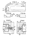
- a folded edge 16 spaced relative to the plane of the wall forming the bottom 12, extends from the periphery of the base element 10. This folded edge 16 is crossed by slots 18 (Fig. 4) and extends to form a curved lip 19 on its outer edge (Fig. 4a and 4b).
- the folded edge 16 of the base member 10 also includes a depression 17 extending over the length of the folded edge, just inside from the slots 18, as best seen in Figs. 3 and 4b.
- the cover 20 also has the general shape of a bowl, with an upper wall 22 rising above a folded edge 26.
- the upper wall 22 has a surface inclined downwards near its center, ending in a hole 28, inlet port.
- the base element 10 and the cover 20 are positioned one against the other, joining by their folded edges 16 and 26 to enclose the volume 30.
- Ribs 24 forming an integral part of the upper wall 22 extend in the volume 30 from the upper wall 22 of the cover 20.
- the upper wall 22 also includes structural ribs 25 (Fig. 1) standing on its surface, as well as various depressions 23 which provide clearance to prevent the filter from interfere with parts of the transmission when the filter is placed in the transmission housing.
- the filter element 40 is enclosed in the volume 30.
- the filter element 40 is an elongated sheet, substantially rectangular, folded in half, forming an envelope whose edges are clamped together between the folded edges 16 and 26, at their junction.
- the dashed line 32 of FIG. 1 delimits the edges of the filter element 40, the part of this line 32 on the left side of FIG. 1 delimiting the fold.
- the fold itself appears most clearly in FIG. 3.
- the filter element 40 comprises a composite assembly which includes a first fine filter material 42 in the form of a sheet having an opening 43 in its surface and a second filter material 44 with a coarse texture, attached to the material 42 over the opening 43
- the periphery of the opening 43 is represented by the dashed line 34 in FIG. 1.
- the filter element 40 has a second opening 45 which is oval.
- the openings 43 and 45 are on opposite sides of the material ply 42, and are thus spaced one above the other in the volume 30.
- the edges of the oval opening 45 correspond to the edges of the entry hole 28 in the upper wall 22 of the cover 20.
- An eyelet 48 whose circumference is continuous sealingly fixes the edges of the oval opening 45 to the entry hole 28 and thus delimits the orifice 6 for entry of the fluid.
- the fluid penetrates into the filter and into the envelope formed by the filter element 40 passing through the inlet orifice 6, as shown by the arrows 8 in FIGS. 1 and 2.
- the fluid passes through the envelope of filtering material 42 and 44, entering the volume 30, and leaves the filter through the outlet tube 4, as shown by the arrows 9 in FIGS. 2 and 3.
- the filter material is interposed between the inlet 6 and the outlet 4 inside the volume 30.
- the present invention achieves hermetic sealing between the plastic cover 20 and the metal base element 10 by the use of a plastic overmold 50 around the meeting of the folded edges 16 and 26, clearly visible in FIGS. 2 and 3.
- a plastic overmold 50 around the meeting of the folded edges 16 and 26, clearly visible in FIGS. 2 and 3.
- the plastic of the overmolding 50 on each side of the folded edge 16 is in direct contact with the plastic on the opposite side, through the slots 18 of the folded edge 16. This helps to keep the overmolding intact.
- the folded lip 19 of the base element 10 is embedded in the plastic of the overmolding 50. The curvature of this lip and the rigidity of the plastic overmolding 50 ensure mechanical locking between the base element 10 and the overmolding. 50.
- the cover 20 has a protuberance 27 on its folded edge 26 which matches the shape of the depression 17 on the left side of the base element 10 (Figs. 3 and 6).
- the depression 17 and the protrusion 27 engaging one on the other achieve mechanical locking of the base element 10 and the cover 20 and prevent lateral movement between them, since they are held together by the overmolding 50.
- hot resin is introduced into the sections 60 of the mold through the casting channel 62 (FIGS. 5 and 6).
- the hot resin from the overmold 50 adheres to the exposed edges of the filter material 42 sandwiched between the folded edges 16 and 26.
- the resin also adheres to the plastic cover 20, thus forming a hermetic seal.
- the parts of the cover 20 coming into contact with the edges of the filter element 40 have a raised lip 29 near the periphery of the folded edge 26.
- This protruding lip 29 is supported by a steel ring 64 of the section of the mold 60 (FIG. 5) during the molding operation.
- This feature has been found useful in preventing the cover 20 from sagging under the molding pressure of the overmolding.
- the cover and the overmolding are made of glass-filled nylon.
- the slots 18 are about 1.5 inches (38 mm) long, about 0.03 inch (0.8 mm) wide, and are spaced about 3 inches (76 mm) from center to center.
- the first fine filter material may be a felt impregnated with resin, and the second coarse texture filter material 44 may be a nylon fabric. It is of course possible to use a uniform filter material (non-composite) in the manufacture of filters benefiting from the hermetic sealing of the present invention.
Landscapes
- Chemical & Material Sciences (AREA)
- Chemical Kinetics & Catalysis (AREA)
- Engineering & Computer Science (AREA)
- General Engineering & Computer Science (AREA)
- Mechanical Engineering (AREA)
- General Details Of Gearings (AREA)
- Filtration Of Liquid (AREA)
Applications Claiming Priority (2)
| Application Number | Priority Date | Filing Date | Title |
|---|---|---|---|
| US06/803,127 US4826598A (en) | 1985-11-29 | 1985-11-29 | Hermetically sealed transmission filter |
| US803127 | 2001-03-08 |
Publications (2)
| Publication Number | Publication Date |
|---|---|
| EP0225828A2 true EP0225828A2 (de) | 1987-06-16 |
| EP0225828A3 EP0225828A3 (de) | 1988-09-07 |
Family
ID=25185652
Family Applications (1)
| Application Number | Title | Priority Date | Filing Date |
|---|---|---|---|
| EP86402613A Withdrawn EP0225828A3 (de) | 1985-11-29 | 1986-11-25 | Hermetisch verschlossener Filter für eine Transmission |
Country Status (3)
| Country | Link |
|---|---|
| US (1) | US4826598A (de) |
| EP (1) | EP0225828A3 (de) |
| JP (1) | JP2509198B2 (de) |
Cited By (7)
| Publication number | Priority date | Publication date | Assignee | Title |
|---|---|---|---|---|
| EP0396385A3 (de) * | 1989-05-01 | 1990-12-19 | Filtertek, Inc. | Reibschweissverfahren und dadurch hergestellter Filter |
| ES2064241A2 (es) * | 1991-12-18 | 1995-01-16 | Mann & Hummel Filter | Filtro para liquidos. |
| EP0659459A3 (de) * | 1993-12-27 | 1996-02-21 | Toyo Roki Seizo Kk | Filtervorrichtung mit einem Gehäuse und Trägerstruktur zum Ferthalten eines Filtermediums. |
| US5507904A (en) * | 1993-09-14 | 1996-04-16 | Baxter International Inc. | Method of making a medical container port tangential to the container |
| US5591337A (en) * | 1993-09-14 | 1997-01-07 | Baxter International Inc. | Apparatus for filtering leukocytes from blood cells |
| EP1941938A1 (de) * | 2006-12-21 | 2008-07-09 | Kyosan Denki Co., Ltd. | Filtervorrichtung und Verfahren zu deren Herstellung |
| WO2017076769A1 (de) * | 2015-11-06 | 2017-05-11 | Robert Bosch Gmbh | Filtermodul sowie spritzgussform und verfahren zum herstellen eines filtermoduls |
Families Citing this family (38)
| Publication number | Priority date | Publication date | Assignee | Title |
|---|---|---|---|---|
| JP3068743B2 (ja) * | 1994-03-24 | 2000-07-24 | 本田技研工業株式会社 | フィルター装置 |
| US5556541A (en) * | 1994-04-26 | 1996-09-17 | Filtertek, Inc. | Process for making hermetically sealed filter units and filters made thereby |
| DE19654188C5 (de) * | 1995-12-26 | 2010-09-23 | Toyoda Boshoku Corp., Kariya-shi | Filterelement und Verfahren für dessen Herstellung |
| US6033455A (en) * | 1996-07-19 | 2000-03-07 | 3M Innovative Properties Company | Repeatedly usable filter frame and filter for fluid using the same |
| US5766469A (en) * | 1996-10-18 | 1998-06-16 | Filtertek, Inc. | Orifice filter |
| US5766472A (en) * | 1996-10-29 | 1998-06-16 | Illinois Tool Works Inc. | Method and apparatus for a filter assembly |
| US5853577A (en) * | 1997-09-22 | 1998-12-29 | Spx Corporation | Orbital vibration welded filter |
| US5863424A (en) * | 1998-05-05 | 1999-01-26 | Dana Corporation | Filter element for oil pans and filter element/oil pan combination |
| USD421025S (en) * | 1998-12-23 | 2000-02-22 | Spx Corporation | Transmission fluid filter |
| USD420682S (en) * | 1999-03-16 | 2000-02-15 | Spx Corporation | Transmission filter assembly |
| USD422600S (en) * | 1999-03-16 | 2000-04-11 | Spx Corporation | Transmission fluid filter |
| US6284181B1 (en) * | 1999-09-07 | 2001-09-04 | Ivan Gaster | Over-molded product and method of manufacture |
| US7282140B2 (en) * | 2001-03-02 | 2007-10-16 | Filtertek Inc. | Sump filter with filter element cartridge |
| DE60220733T2 (de) * | 2001-03-02 | 2007-10-18 | Filtertek, Inc., Hebron | Ölwannenfilter mit Filterpatrone |
| US6887174B2 (en) * | 2001-08-06 | 2005-05-03 | Denso Corporation | Hydraulic pressure control apparatus |
| JP3595311B2 (ja) * | 2002-03-28 | 2004-12-02 | 川崎重工業株式会社 | エンジンのエアクリーナ |
| CA2472611C (en) * | 2003-07-02 | 2009-09-15 | Illinois Tool Works Inc. | Multiple retainer bridge |
| US20050045566A1 (en) * | 2003-08-29 | 2005-03-03 | Larry Larkin | Filtration media created by sonic welding |
| US7312949B2 (en) * | 2003-10-22 | 2007-12-25 | Seagate Technology Llc | Base deck with overmolded elastomeric and rigid structural components |
| JPWO2007010721A1 (ja) * | 2005-07-21 | 2009-01-29 | Nok株式会社 | オイルストレーナ |
| FI20060319A7 (fi) * | 2006-03-31 | 2007-10-01 | Stora Enso Oyj | Menetelmä pakkausten sulkemiseksi ja pakkaus |
| DE102007005399A1 (de) * | 2007-02-03 | 2008-08-07 | Zf Friedrichshafen Ag | Saugfilter für Öl eines Getriebes und/oder eines Motors |
| DE102007023641B4 (de) * | 2007-05-22 | 2015-04-02 | Ibs Filtran Kunststoff-/ Metallerzeugnisse Gmbh | Ölfiltervorrichtung |
| US8377358B2 (en) * | 2008-05-05 | 2013-02-19 | Dow Global Technologies Llc | Method for encapsulating the edge of a flexible sheet |
| DE102008027662A1 (de) * | 2008-06-10 | 2009-12-17 | Ibs Filtran Kunststoff- / Metallerzeugnisse Gmbh | Ölwanne mit Ölfilter |
| US9123847B2 (en) | 2010-12-17 | 2015-09-01 | Dow Global Technologies Llc | Photovoltaic device |
| US9427685B2 (en) | 2012-09-20 | 2016-08-30 | Ford Global Technologies, Llc | Suction filter media overmolded integrally with tray |
| US20150108682A1 (en) * | 2013-10-23 | 2015-04-23 | Lincoln Global, Inc. | Method of making a filter seal |
| DE102014209736A1 (de) * | 2014-05-22 | 2015-11-26 | BSH Hausgeräte GmbH | Spülflüssigkeits-Filtervorrichtung für eine Wäschebehandlungsmaschine |
| JP6410578B2 (ja) * | 2014-11-20 | 2018-10-24 | ダイキョーニシカワ株式会社 | オイルストレーナ |
| USD820456S1 (en) | 2015-06-09 | 2018-06-12 | Lincoln Global, Inc. | Belt bracket of powered air purifying respirator |
| USD821445S1 (en) * | 2016-05-10 | 2018-06-26 | Ibs Filtran Kunststoff-/Metallerzeugnisse Gmbh | Oil pan with integrated suction filter |
| JP6727954B2 (ja) * | 2016-06-28 | 2020-07-22 | キヤノン株式会社 | 液体供給部品の製造方法、および製造装置 |
| USD857306S1 (en) | 2018-03-07 | 2019-08-20 | Lincoln Global, Inc. | Top of helmet shell |
| USD853044S1 (en) | 2018-03-07 | 2019-07-02 | Lincoln Global, Inc. | Inner shell of a helmet |
| USD860546S1 (en) | 2018-03-07 | 2019-09-17 | Lincoln Global, Inc. | Top shell for helmet |
| USD848077S1 (en) | 2018-03-07 | 2019-05-07 | Lincoln Global, Inc. | Cover lens frame |
| USD851841S1 (en) | 2018-03-23 | 2019-06-18 | Lincoln Global, Inc. | Shield holder frame |
Family Cites Families (16)
| Publication number | Priority date | Publication date | Assignee | Title |
|---|---|---|---|---|
| US3686835A (en) * | 1970-11-27 | 1972-08-29 | Mine Safety Appliances Co | Filter cassette with removable capsule |
| BE788211A (fr) * | 1971-09-16 | 1973-02-28 | Pall Corp | Appareil disposable pour filtrer les gaz |
| BE788210A (fr) * | 1971-09-16 | 1973-02-28 | Pall Corp | Boite filtrante |
| US3796027A (en) * | 1972-07-21 | 1974-03-12 | Briggs & Stratton Corp | Fastening for small engine carburetor air cleaner |
| BR7309041D0 (pt) * | 1973-02-21 | 1974-10-22 | Ghh Basel Ag | Dispositivo para filtragem e/ou tratamento de substancias liquidas ou gasosas |
| DE2354269A1 (de) * | 1973-10-30 | 1975-05-07 | Weppler Ohg | Durchlauffilter nach art eines membranfilters |
| US3932153A (en) * | 1974-02-14 | 1976-01-13 | John Byrns | Nebulizer bacteria filter |
| US3872576A (en) * | 1974-04-01 | 1975-03-25 | Lambert H Mott | Inline filter construction |
| US3957469A (en) * | 1975-02-03 | 1976-05-18 | Mine Safety Appliances Company | Filter cassette with removable capsule |
| US4113627A (en) * | 1976-01-28 | 1978-09-12 | Filtertek, Inc. | Process for making hermetically sealed filter units and filters made thereby |
| US4136011A (en) * | 1977-11-23 | 1979-01-23 | Sealed Power Corporation | Transmission fluid filter and method for manufacture thereof |
| US4402827A (en) * | 1980-07-11 | 1983-09-06 | Sealed Power Corporation | Transmission fluid filter |
| US4404006A (en) * | 1981-06-19 | 1983-09-13 | Williams Charles D | Filter device |
| US4450081A (en) * | 1981-07-16 | 1984-05-22 | Sealed Power Corporation | Transmission fluid filter and method of manufacture |
| DE3145320C2 (de) * | 1981-11-14 | 1987-03-19 | Biotest-Serum-Institut Gmbh, 6000 Frankfurt | Mikrofiltrationsgerät zur Filtration von Koageln und Mikroaggregaten von Blut |
| US4414172A (en) * | 1982-05-21 | 1983-11-08 | Filtertek, Inc. | Process and apparatus for sealing a plurality of filter elements |
-
1985
- 1985-11-29 US US06/803,127 patent/US4826598A/en not_active Expired - Lifetime
-
1986
- 1986-11-25 EP EP86402613A patent/EP0225828A3/de not_active Withdrawn
- 1986-11-28 JP JP61284124A patent/JP2509198B2/ja not_active Expired - Lifetime
Cited By (9)
| Publication number | Priority date | Publication date | Assignee | Title |
|---|---|---|---|---|
| US5049274A (en) * | 1988-01-11 | 1991-09-17 | Filtertek, Inc. | Friction welding process and filter formed thereby |
| EP0396385A3 (de) * | 1989-05-01 | 1990-12-19 | Filtertek, Inc. | Reibschweissverfahren und dadurch hergestellter Filter |
| ES2064241A2 (es) * | 1991-12-18 | 1995-01-16 | Mann & Hummel Filter | Filtro para liquidos. |
| US5507904A (en) * | 1993-09-14 | 1996-04-16 | Baxter International Inc. | Method of making a medical container port tangential to the container |
| US5591337A (en) * | 1993-09-14 | 1997-01-07 | Baxter International Inc. | Apparatus for filtering leukocytes from blood cells |
| US5772880A (en) * | 1993-09-14 | 1998-06-30 | Baxter International, Inc. | Container with a tangential port |
| EP0659459A3 (de) * | 1993-12-27 | 1996-02-21 | Toyo Roki Seizo Kk | Filtervorrichtung mit einem Gehäuse und Trägerstruktur zum Ferthalten eines Filtermediums. |
| EP1941938A1 (de) * | 2006-12-21 | 2008-07-09 | Kyosan Denki Co., Ltd. | Filtervorrichtung und Verfahren zu deren Herstellung |
| WO2017076769A1 (de) * | 2015-11-06 | 2017-05-11 | Robert Bosch Gmbh | Filtermodul sowie spritzgussform und verfahren zum herstellen eines filtermoduls |
Also Published As
| Publication number | Publication date |
|---|---|
| JP2509198B2 (ja) | 1996-06-19 |
| US4826598A (en) | 1989-05-02 |
| JPS62132516A (ja) | 1987-06-15 |
| EP0225828A3 (de) | 1988-09-07 |
Similar Documents
| Publication | Publication Date | Title |
|---|---|---|
| US4826598A (en) | Hermetically sealed transmission filter | |
| FR2921000A1 (fr) | Cartouche filtrante | |
| FR2497554A1 (fr) | Soupape de surpression pour un sac d'emballage ferme de maniere etanche aux gaz et procede pour sa pose | |
| FR2509628A1 (fr) | Element filtrant tubulaire pour la filtration de fluides, et son procede de realisation | |
| FR2685217A1 (fr) | Filtre pour liquides, dont le changement de l'element de filtre et son etancheite s'effectue sans inconvenient. | |
| FR2689783A1 (fr) | Connecteur pour l'étanchéification d'éléments empilés de filtre. | |
| FR2514423A1 (fr) | Filtre d'aspiration d'air pour moteurs a combustion interne compresseurs et autres machines a aspiration d'air | |
| FR2550848A1 (fr) | Volet, en particulier pour installation de chauffage ou de climatisation d'un habitacle de vehicule, et son procede de fabrication | |
| EP0779488B1 (de) | Wärmetauscher,insbesondere für Kraftfahrzeuge | |
| FR2883198A1 (fr) | Systeme de filtration de liquide avec rechauffage | |
| FR2690632A1 (fr) | Filtre destiné à filtrer un fluide agressif. | |
| FR2598936A1 (fr) | Filtre a liquides | |
| EP0222636B1 (de) | Wärmeaustauscher, insbesondere für Kraftfahrzeuge | |
| EP1905971B1 (de) | Vorrichtung zur Trennung bestimmter Stoffe, die von einem Verbrennungsmotor produziert werden | |
| FR2791579A1 (fr) | Cartouche filtrante demontable et recyclable pour filtres a liquide immerges | |
| FR2826591A1 (fr) | Element de filtration a garniture filtrante plissee | |
| FR2536329A1 (fr) | Procede de noyage de membranes dans un materiau thermoplastique | |
| EP2353691A1 (de) | Filterelement mit Lippendichtung für einen Flüssigkeitsfilter | |
| EP1312405B1 (de) | Filterelement für Flüssigkeitfilter eines Verbrennungsmotors, Filter mit einem solchen Filterelement und Kraftfahrzeug mit einem solchen Filter | |
| FR2484533A1 (fr) | Vase compensateur pour eau de refroidissement | |
| FR2774103A1 (fr) | Reservoir d'eau pour fer a vapeur, et procede de fabrication d'un tel reservoir | |
| FR2824750A1 (fr) | Element de filtre rond | |
| EP1469288B1 (de) | Wassermesser mit volumetrischer Messkammer | |
| EP1477215A1 (de) | Filterkartusche für Filter für Flüssigkeiten von Verbrennungsmotoren und Filter, der eine solche Filterkartusche enthält | |
| EP1714689B1 (de) | Filterelement, Filtrationsystem mit einem solchen Filterelement und Verfahren zur Herstellung eines solchen Filtrationsystems |
Legal Events
| Date | Code | Title | Description |
|---|---|---|---|
| PUAI | Public reference made under article 153(3) epc to a published international application that has entered the european phase |
Free format text: ORIGINAL CODE: 0009012 |
|
| AK | Designated contracting states |
Kind code of ref document: A2 Designated state(s): DE ES FR GB IT NL |
|
| RAP1 | Party data changed (applicant data changed or rights of an application transferred) |
Owner name: FILTERTEK S.A. |
|
| PUAL | Search report despatched |
Free format text: ORIGINAL CODE: 0009013 |
|
| AK | Designated contracting states |
Kind code of ref document: A3 Designated state(s): DE ES FR GB IT NL |
|
| 17P | Request for examination filed |
Effective date: 19890207 |
|
| 17Q | First examination report despatched |
Effective date: 19900112 |
|
| STAA | Information on the status of an ep patent application or granted ep patent |
Free format text: STATUS: THE APPLICATION HAS BEEN WITHDRAWN |
|
| 18W | Application withdrawn |
Withdrawal date: 19900317 |
|
| R18W | Application withdrawn (corrected) |
Effective date: 19900317 |
|
| RIN1 | Information on inventor provided before grant (corrected) |
Inventor name: CAIN, THOMAS A. |