EP0225911B1 - Erhöhte argonwiedergewinnung bei der luftdistillierung - Google Patents
Erhöhte argonwiedergewinnung bei der luftdistillierung Download PDFInfo
- Publication number
- EP0225911B1 EP0225911B1 EP86903748A EP86903748A EP0225911B1 EP 0225911 B1 EP0225911 B1 EP 0225911B1 EP 86903748 A EP86903748 A EP 86903748A EP 86903748 A EP86903748 A EP 86903748A EP 0225911 B1 EP0225911 B1 EP 0225911B1
- Authority
- EP
- European Patent Office
- Prior art keywords
- argon
- section
- liquid
- rectifier
- latent heat
- Prior art date
- Legal status (The legal status is an assumption and is not a legal conclusion. Google has not performed a legal analysis and makes no representation as to the accuracy of the status listed.)
- Expired - Lifetime
Links
- XKRFYHLGVUSROY-UHFFFAOYSA-N Argon Chemical compound [Ar] XKRFYHLGVUSROY-UHFFFAOYSA-N 0.000 title claims abstract description 292
- 229910052786 argon Inorganic materials 0.000 title claims abstract description 146
- 238000011084 recovery Methods 0.000 title claims abstract description 49
- 230000001965 increasing effect Effects 0.000 title claims abstract description 27
- 238000004821 distillation Methods 0.000 title claims abstract description 9
- QVGXLLKOCUKJST-UHFFFAOYSA-N atomic oxygen Chemical compound [O] QVGXLLKOCUKJST-UHFFFAOYSA-N 0.000 claims abstract description 29
- 239000001301 oxygen Substances 0.000 claims abstract description 29
- 229910052760 oxygen Inorganic materials 0.000 claims abstract description 29
- 238000000034 method Methods 0.000 claims abstract description 19
- 230000008569 process Effects 0.000 claims abstract description 19
- 239000012530 fluid Substances 0.000 claims abstract description 8
- IJGRMHOSHXDMSA-UHFFFAOYSA-N Atomic nitrogen Chemical compound N#N IJGRMHOSHXDMSA-UHFFFAOYSA-N 0.000 claims description 66
- 239000007788 liquid Substances 0.000 claims description 62
- 238000010992 reflux Methods 0.000 claims description 41
- 229910052757 nitrogen Inorganic materials 0.000 claims description 33
- 239000000047 product Substances 0.000 claims description 28
- MYMOFIZGZYHOMD-UHFFFAOYSA-N Dioxygen Chemical compound O=O MYMOFIZGZYHOMD-UHFFFAOYSA-N 0.000 claims description 17
- 238000001704 evaporation Methods 0.000 claims description 15
- 238000005057 refrigeration Methods 0.000 claims description 14
- 239000007789 gas Substances 0.000 claims description 7
- 230000009977 dual effect Effects 0.000 claims description 6
- 230000006872 improvement Effects 0.000 claims description 6
- QJGQUHMNIGDVPM-UHFFFAOYSA-N nitrogen group Chemical group [N] QJGQUHMNIGDVPM-UHFFFAOYSA-N 0.000 claims description 5
- 239000006227 byproduct Substances 0.000 claims description 2
- 230000007423 decrease Effects 0.000 description 10
- 238000009833 condensation Methods 0.000 description 6
- 230000005494 condensation Effects 0.000 description 6
- 230000003247 decreasing effect Effects 0.000 description 6
- 230000002411 adverse Effects 0.000 description 5
- 230000008020 evaporation Effects 0.000 description 4
- 230000036961 partial effect Effects 0.000 description 4
- 230000002829 reductive effect Effects 0.000 description 4
- VVTSZOCINPYFDP-UHFFFAOYSA-N [O].[Ar] Chemical compound [O].[Ar] VVTSZOCINPYFDP-UHFFFAOYSA-N 0.000 description 3
- 238000004519 manufacturing process Methods 0.000 description 3
- 239000000203 mixture Substances 0.000 description 3
- 239000004215 Carbon black (E152) Substances 0.000 description 2
- 230000008859 change Effects 0.000 description 2
- 230000000694 effects Effects 0.000 description 2
- 229930195733 hydrocarbon Natural products 0.000 description 2
- 150000002430 hydrocarbons Chemical class 0.000 description 2
- 238000010348 incorporation Methods 0.000 description 2
- 238000002347 injection Methods 0.000 description 2
- 239000007924 injection Substances 0.000 description 2
- 230000009467 reduction Effects 0.000 description 2
- 238000000926 separation method Methods 0.000 description 2
- 239000006200 vaporizer Substances 0.000 description 2
- 229910000831 Steel Inorganic materials 0.000 description 1
- 230000000996 additive effect Effects 0.000 description 1
- 238000013459 approach Methods 0.000 description 1
- 230000009286 beneficial effect Effects 0.000 description 1
- 238000009835 boiling Methods 0.000 description 1
- 238000003889 chemical engineering Methods 0.000 description 1
- 238000004140 cleaning Methods 0.000 description 1
- 238000001816 cooling Methods 0.000 description 1
- 230000002079 cooperative effect Effects 0.000 description 1
- 230000000875 corresponding effect Effects 0.000 description 1
- 238000012217 deletion Methods 0.000 description 1
- 230000037430 deletion Effects 0.000 description 1
- 238000010586 diagram Methods 0.000 description 1
- 238000001035 drying Methods 0.000 description 1
- 238000002309 gasification Methods 0.000 description 1
- 239000012535 impurity Substances 0.000 description 1
- 230000001939 inductive effect Effects 0.000 description 1
- 239000007791 liquid phase Substances 0.000 description 1
- 239000012263 liquid product Substances 0.000 description 1
- 239000012071 phase Substances 0.000 description 1
- 238000000746 purification Methods 0.000 description 1
- 230000002441 reversible effect Effects 0.000 description 1
- 239000010959 steel Substances 0.000 description 1
- 238000006467 substitution reaction Methods 0.000 description 1
- 238000012546 transfer Methods 0.000 description 1
- 239000012808 vapor phase Substances 0.000 description 1
- 238000010792 warming Methods 0.000 description 1
- 239000002699 waste material Substances 0.000 description 1
- 238000003466 welding Methods 0.000 description 1
Images

Classifications
-
- F—MECHANICAL ENGINEERING; LIGHTING; HEATING; WEAPONS; BLASTING
- F25—REFRIGERATION OR COOLING; COMBINED HEATING AND REFRIGERATION SYSTEMS; HEAT PUMP SYSTEMS; MANUFACTURE OR STORAGE OF ICE; LIQUEFACTION SOLIDIFICATION OF GASES
- F25J—LIQUEFACTION, SOLIDIFICATION OR SEPARATION OF GASES OR GASEOUS OR LIQUEFIED GASEOUS MIXTURES BY PRESSURE AND COLD TREATMENT OR BY BRINGING THEM INTO THE SUPERCRITICAL STATE
- F25J3/00—Processes or apparatus for separating the constituents of gaseous or liquefied gaseous mixtures involving the use of liquefaction or solidification
- F25J3/02—Processes or apparatus for separating the constituents of gaseous or liquefied gaseous mixtures involving the use of liquefaction or solidification by rectification, i.e. by continuous interchange of heat and material between a vapour stream and a liquid stream
- F25J3/04—Processes or apparatus for separating the constituents of gaseous or liquefied gaseous mixtures involving the use of liquefaction or solidification by rectification, i.e. by continuous interchange of heat and material between a vapour stream and a liquid stream for air
- F25J3/04006—Providing pressurised feed air or process streams within or from the air fractionation unit
- F25J3/04078—Providing pressurised feed air or process streams within or from the air fractionation unit providing pressurized products by liquid compression and vaporisation with cold recovery, i.e. so-called internal compression
- F25J3/04103—Providing pressurised feed air or process streams within or from the air fractionation unit providing pressurized products by liquid compression and vaporisation with cold recovery, i.e. so-called internal compression using solely hydrostatic liquid head
-
- F—MECHANICAL ENGINEERING; LIGHTING; HEATING; WEAPONS; BLASTING
- F25—REFRIGERATION OR COOLING; COMBINED HEATING AND REFRIGERATION SYSTEMS; HEAT PUMP SYSTEMS; MANUFACTURE OR STORAGE OF ICE; LIQUEFACTION SOLIDIFICATION OF GASES
- F25J—LIQUEFACTION, SOLIDIFICATION OR SEPARATION OF GASES OR GASEOUS OR LIQUEFIED GASEOUS MIXTURES BY PRESSURE AND COLD TREATMENT OR BY BRINGING THEM INTO THE SUPERCRITICAL STATE
- F25J3/00—Processes or apparatus for separating the constituents of gaseous or liquefied gaseous mixtures involving the use of liquefaction or solidification
- F25J3/02—Processes or apparatus for separating the constituents of gaseous or liquefied gaseous mixtures involving the use of liquefaction or solidification by rectification, i.e. by continuous interchange of heat and material between a vapour stream and a liquid stream
- F25J3/04—Processes or apparatus for separating the constituents of gaseous or liquefied gaseous mixtures involving the use of liquefaction or solidification by rectification, i.e. by continuous interchange of heat and material between a vapour stream and a liquid stream for air
-
- F—MECHANICAL ENGINEERING; LIGHTING; HEATING; WEAPONS; BLASTING
- F25—REFRIGERATION OR COOLING; COMBINED HEATING AND REFRIGERATION SYSTEMS; HEAT PUMP SYSTEMS; MANUFACTURE OR STORAGE OF ICE; LIQUEFACTION SOLIDIFICATION OF GASES
- F25J—LIQUEFACTION, SOLIDIFICATION OR SEPARATION OF GASES OR GASEOUS OR LIQUEFIED GASEOUS MIXTURES BY PRESSURE AND COLD TREATMENT OR BY BRINGING THEM INTO THE SUPERCRITICAL STATE
- F25J3/00—Processes or apparatus for separating the constituents of gaseous or liquefied gaseous mixtures involving the use of liquefaction or solidification
- F25J3/02—Processes or apparatus for separating the constituents of gaseous or liquefied gaseous mixtures involving the use of liquefaction or solidification by rectification, i.e. by continuous interchange of heat and material between a vapour stream and a liquid stream
- F25J3/04—Processes or apparatus for separating the constituents of gaseous or liquefied gaseous mixtures involving the use of liquefaction or solidification by rectification, i.e. by continuous interchange of heat and material between a vapour stream and a liquid stream for air
- F25J3/04006—Providing pressurised feed air or process streams within or from the air fractionation unit
- F25J3/04078—Providing pressurised feed air or process streams within or from the air fractionation unit providing pressurized products by liquid compression and vaporisation with cold recovery, i.e. so-called internal compression
- F25J3/0409—Providing pressurised feed air or process streams within or from the air fractionation unit providing pressurized products by liquid compression and vaporisation with cold recovery, i.e. so-called internal compression of oxygen
-
- F—MECHANICAL ENGINEERING; LIGHTING; HEATING; WEAPONS; BLASTING
- F25—REFRIGERATION OR COOLING; COMBINED HEATING AND REFRIGERATION SYSTEMS; HEAT PUMP SYSTEMS; MANUFACTURE OR STORAGE OF ICE; LIQUEFACTION SOLIDIFICATION OF GASES
- F25J—LIQUEFACTION, SOLIDIFICATION OR SEPARATION OF GASES OR GASEOUS OR LIQUEFIED GASEOUS MIXTURES BY PRESSURE AND COLD TREATMENT OR BY BRINGING THEM INTO THE SUPERCRITICAL STATE
- F25J3/00—Processes or apparatus for separating the constituents of gaseous or liquefied gaseous mixtures involving the use of liquefaction or solidification
- F25J3/02—Processes or apparatus for separating the constituents of gaseous or liquefied gaseous mixtures involving the use of liquefaction or solidification by rectification, i.e. by continuous interchange of heat and material between a vapour stream and a liquid stream
- F25J3/04—Processes or apparatus for separating the constituents of gaseous or liquefied gaseous mixtures involving the use of liquefaction or solidification by rectification, i.e. by continuous interchange of heat and material between a vapour stream and a liquid stream for air
- F25J3/04151—Purification and (pre-)cooling of the feed air; recuperative heat-exchange with product streams
- F25J3/04187—Cooling of the purified feed air by recuperative heat-exchange; Heat-exchange with product streams
- F25J3/04193—Division of the main heat exchange line in consecutive sections having different functions
- F25J3/04206—Division of the main heat exchange line in consecutive sections having different functions including a so-called "auxiliary vaporiser" for vaporising and producing a gaseous product
-
- F—MECHANICAL ENGINEERING; LIGHTING; HEATING; WEAPONS; BLASTING
- F25—REFRIGERATION OR COOLING; COMBINED HEATING AND REFRIGERATION SYSTEMS; HEAT PUMP SYSTEMS; MANUFACTURE OR STORAGE OF ICE; LIQUEFACTION SOLIDIFICATION OF GASES
- F25J—LIQUEFACTION, SOLIDIFICATION OR SEPARATION OF GASES OR GASEOUS OR LIQUEFIED GASEOUS MIXTURES BY PRESSURE AND COLD TREATMENT OR BY BRINGING THEM INTO THE SUPERCRITICAL STATE
- F25J3/00—Processes or apparatus for separating the constituents of gaseous or liquefied gaseous mixtures involving the use of liquefaction or solidification
- F25J3/02—Processes or apparatus for separating the constituents of gaseous or liquefied gaseous mixtures involving the use of liquefaction or solidification by rectification, i.e. by continuous interchange of heat and material between a vapour stream and a liquid stream
- F25J3/04—Processes or apparatus for separating the constituents of gaseous or liquefied gaseous mixtures involving the use of liquefaction or solidification by rectification, i.e. by continuous interchange of heat and material between a vapour stream and a liquid stream for air
- F25J3/04248—Generation of cold for compensating heat leaks or liquid production, e.g. by Joule-Thompson expansion
- F25J3/04284—Generation of cold for compensating heat leaks or liquid production, e.g. by Joule-Thompson expansion using internal refrigeration by open-loop gas work expansion, e.g. of intermediate or oxygen enriched (waste-)streams
- F25J3/0429—Generation of cold for compensating heat leaks or liquid production, e.g. by Joule-Thompson expansion using internal refrigeration by open-loop gas work expansion, e.g. of intermediate or oxygen enriched (waste-)streams of feed air, e.g. used as waste or product air or expanded into an auxiliary column
- F25J3/04303—Lachmann expansion, i.e. expanded into oxygen producing or low pressure column
-
- F—MECHANICAL ENGINEERING; LIGHTING; HEATING; WEAPONS; BLASTING
- F25—REFRIGERATION OR COOLING; COMBINED HEATING AND REFRIGERATION SYSTEMS; HEAT PUMP SYSTEMS; MANUFACTURE OR STORAGE OF ICE; LIQUEFACTION SOLIDIFICATION OF GASES
- F25J—LIQUEFACTION, SOLIDIFICATION OR SEPARATION OF GASES OR GASEOUS OR LIQUEFIED GASEOUS MIXTURES BY PRESSURE AND COLD TREATMENT OR BY BRINGING THEM INTO THE SUPERCRITICAL STATE
- F25J3/00—Processes or apparatus for separating the constituents of gaseous or liquefied gaseous mixtures involving the use of liquefaction or solidification
- F25J3/02—Processes or apparatus for separating the constituents of gaseous or liquefied gaseous mixtures involving the use of liquefaction or solidification by rectification, i.e. by continuous interchange of heat and material between a vapour stream and a liquid stream
- F25J3/04—Processes or apparatus for separating the constituents of gaseous or liquefied gaseous mixtures involving the use of liquefaction or solidification by rectification, i.e. by continuous interchange of heat and material between a vapour stream and a liquid stream for air
- F25J3/04248—Generation of cold for compensating heat leaks or liquid production, e.g. by Joule-Thompson expansion
- F25J3/04284—Generation of cold for compensating heat leaks or liquid production, e.g. by Joule-Thompson expansion using internal refrigeration by open-loop gas work expansion, e.g. of intermediate or oxygen enriched (waste-)streams
- F25J3/04309—Generation of cold for compensating heat leaks or liquid production, e.g. by Joule-Thompson expansion using internal refrigeration by open-loop gas work expansion, e.g. of intermediate or oxygen enriched (waste-)streams of nitrogen
-
- F—MECHANICAL ENGINEERING; LIGHTING; HEATING; WEAPONS; BLASTING
- F25—REFRIGERATION OR COOLING; COMBINED HEATING AND REFRIGERATION SYSTEMS; HEAT PUMP SYSTEMS; MANUFACTURE OR STORAGE OF ICE; LIQUEFACTION SOLIDIFICATION OF GASES
- F25J—LIQUEFACTION, SOLIDIFICATION OR SEPARATION OF GASES OR GASEOUS OR LIQUEFIED GASEOUS MIXTURES BY PRESSURE AND COLD TREATMENT OR BY BRINGING THEM INTO THE SUPERCRITICAL STATE
- F25J3/00—Processes or apparatus for separating the constituents of gaseous or liquefied gaseous mixtures involving the use of liquefaction or solidification
- F25J3/02—Processes or apparatus for separating the constituents of gaseous or liquefied gaseous mixtures involving the use of liquefaction or solidification by rectification, i.e. by continuous interchange of heat and material between a vapour stream and a liquid stream
- F25J3/04—Processes or apparatus for separating the constituents of gaseous or liquefied gaseous mixtures involving the use of liquefaction or solidification by rectification, i.e. by continuous interchange of heat and material between a vapour stream and a liquid stream for air
- F25J3/04248—Generation of cold for compensating heat leaks or liquid production, e.g. by Joule-Thompson expansion
- F25J3/04375—Details relating to the work expansion, e.g. process parameter etc.
- F25J3/04393—Details relating to the work expansion, e.g. process parameter etc. using multiple or multistage gas work expansion
-
- F—MECHANICAL ENGINEERING; LIGHTING; HEATING; WEAPONS; BLASTING
- F25—REFRIGERATION OR COOLING; COMBINED HEATING AND REFRIGERATION SYSTEMS; HEAT PUMP SYSTEMS; MANUFACTURE OR STORAGE OF ICE; LIQUEFACTION SOLIDIFICATION OF GASES
- F25J—LIQUEFACTION, SOLIDIFICATION OR SEPARATION OF GASES OR GASEOUS OR LIQUEFIED GASEOUS MIXTURES BY PRESSURE AND COLD TREATMENT OR BY BRINGING THEM INTO THE SUPERCRITICAL STATE
- F25J3/00—Processes or apparatus for separating the constituents of gaseous or liquefied gaseous mixtures involving the use of liquefaction or solidification
- F25J3/02—Processes or apparatus for separating the constituents of gaseous or liquefied gaseous mixtures involving the use of liquefaction or solidification by rectification, i.e. by continuous interchange of heat and material between a vapour stream and a liquid stream
- F25J3/04—Processes or apparatus for separating the constituents of gaseous or liquefied gaseous mixtures involving the use of liquefaction or solidification by rectification, i.e. by continuous interchange of heat and material between a vapour stream and a liquid stream for air
- F25J3/04406—Processes or apparatus for separating the constituents of gaseous or liquefied gaseous mixtures involving the use of liquefaction or solidification by rectification, i.e. by continuous interchange of heat and material between a vapour stream and a liquid stream for air using a dual pressure main column system
- F25J3/04412—Processes or apparatus for separating the constituents of gaseous or liquefied gaseous mixtures involving the use of liquefaction or solidification by rectification, i.e. by continuous interchange of heat and material between a vapour stream and a liquid stream for air using a dual pressure main column system in a classical double column flowsheet, i.e. with thermal coupling by a main reboiler-condenser in the bottom of low pressure respectively top of high pressure column
-
- F—MECHANICAL ENGINEERING; LIGHTING; HEATING; WEAPONS; BLASTING
- F25—REFRIGERATION OR COOLING; COMBINED HEATING AND REFRIGERATION SYSTEMS; HEAT PUMP SYSTEMS; MANUFACTURE OR STORAGE OF ICE; LIQUEFACTION SOLIDIFICATION OF GASES
- F25J—LIQUEFACTION, SOLIDIFICATION OR SEPARATION OF GASES OR GASEOUS OR LIQUEFIED GASEOUS MIXTURES BY PRESSURE AND COLD TREATMENT OR BY BRINGING THEM INTO THE SUPERCRITICAL STATE
- F25J3/00—Processes or apparatus for separating the constituents of gaseous or liquefied gaseous mixtures involving the use of liquefaction or solidification
- F25J3/02—Processes or apparatus for separating the constituents of gaseous or liquefied gaseous mixtures involving the use of liquefaction or solidification by rectification, i.e. by continuous interchange of heat and material between a vapour stream and a liquid stream
- F25J3/04—Processes or apparatus for separating the constituents of gaseous or liquefied gaseous mixtures involving the use of liquefaction or solidification by rectification, i.e. by continuous interchange of heat and material between a vapour stream and a liquid stream for air
- F25J3/04642—Recovering noble gases from air
- F25J3/04648—Recovering noble gases from air argon
- F25J3/04654—Producing crude argon in a crude argon column
- F25J3/04666—Producing crude argon in a crude argon column as a parallel working rectification column of the low pressure column in a dual pressure main column system
- F25J3/04672—Producing crude argon in a crude argon column as a parallel working rectification column of the low pressure column in a dual pressure main column system having a top condenser
- F25J3/04678—Producing crude argon in a crude argon column as a parallel working rectification column of the low pressure column in a dual pressure main column system having a top condenser cooled by oxygen enriched liquid from high pressure column bottoms
-
- F—MECHANICAL ENGINEERING; LIGHTING; HEATING; WEAPONS; BLASTING
- F25—REFRIGERATION OR COOLING; COMBINED HEATING AND REFRIGERATION SYSTEMS; HEAT PUMP SYSTEMS; MANUFACTURE OR STORAGE OF ICE; LIQUEFACTION SOLIDIFICATION OF GASES
- F25J—LIQUEFACTION, SOLIDIFICATION OR SEPARATION OF GASES OR GASEOUS OR LIQUEFIED GASEOUS MIXTURES BY PRESSURE AND COLD TREATMENT OR BY BRINGING THEM INTO THE SUPERCRITICAL STATE
- F25J3/00—Processes or apparatus for separating the constituents of gaseous or liquefied gaseous mixtures involving the use of liquefaction or solidification
- F25J3/02—Processes or apparatus for separating the constituents of gaseous or liquefied gaseous mixtures involving the use of liquefaction or solidification by rectification, i.e. by continuous interchange of heat and material between a vapour stream and a liquid stream
- F25J3/04—Processes or apparatus for separating the constituents of gaseous or liquefied gaseous mixtures involving the use of liquefaction or solidification by rectification, i.e. by continuous interchange of heat and material between a vapour stream and a liquid stream for air
- F25J3/04642—Recovering noble gases from air
- F25J3/04648—Recovering noble gases from air argon
- F25J3/04654—Producing crude argon in a crude argon column
- F25J3/04666—Producing crude argon in a crude argon column as a parallel working rectification column of the low pressure column in a dual pressure main column system
- F25J3/04672—Producing crude argon in a crude argon column as a parallel working rectification column of the low pressure column in a dual pressure main column system having a top condenser
- F25J3/0469—Producing crude argon in a crude argon column as a parallel working rectification column of the low pressure column in a dual pressure main column system having a top condenser and an intermediate re-boiler/condenser
-
- F—MECHANICAL ENGINEERING; LIGHTING; HEATING; WEAPONS; BLASTING
- F25—REFRIGERATION OR COOLING; COMBINED HEATING AND REFRIGERATION SYSTEMS; HEAT PUMP SYSTEMS; MANUFACTURE OR STORAGE OF ICE; LIQUEFACTION SOLIDIFICATION OF GASES
- F25J—LIQUEFACTION, SOLIDIFICATION OR SEPARATION OF GASES OR GASEOUS OR LIQUEFIED GASEOUS MIXTURES BY PRESSURE AND COLD TREATMENT OR BY BRINGING THEM INTO THE SUPERCRITICAL STATE
- F25J2200/00—Processes or apparatus using separation by rectification
- F25J2200/50—Processes or apparatus using separation by rectification using multiple (re-)boiler-condensers at different heights of the column
- F25J2200/54—Processes or apparatus using separation by rectification using multiple (re-)boiler-condensers at different heights of the column in the low pressure column of a double pressure main column system
-
- F—MECHANICAL ENGINEERING; LIGHTING; HEATING; WEAPONS; BLASTING
- F25—REFRIGERATION OR COOLING; COMBINED HEATING AND REFRIGERATION SYSTEMS; HEAT PUMP SYSTEMS; MANUFACTURE OR STORAGE OF ICE; LIQUEFACTION SOLIDIFICATION OF GASES
- F25J—LIQUEFACTION, SOLIDIFICATION OR SEPARATION OF GASES OR GASEOUS OR LIQUEFIED GASEOUS MIXTURES BY PRESSURE AND COLD TREATMENT OR BY BRINGING THEM INTO THE SUPERCRITICAL STATE
- F25J2205/00—Processes or apparatus using other separation and/or other processing means
- F25J2205/02—Processes or apparatus using other separation and/or other processing means using simple phase separation in a vessel or drum
-
- F—MECHANICAL ENGINEERING; LIGHTING; HEATING; WEAPONS; BLASTING
- F25—REFRIGERATION OR COOLING; COMBINED HEATING AND REFRIGERATION SYSTEMS; HEAT PUMP SYSTEMS; MANUFACTURE OR STORAGE OF ICE; LIQUEFACTION SOLIDIFICATION OF GASES
- F25J—LIQUEFACTION, SOLIDIFICATION OR SEPARATION OF GASES OR GASEOUS OR LIQUEFIED GASEOUS MIXTURES BY PRESSURE AND COLD TREATMENT OR BY BRINGING THEM INTO THE SUPERCRITICAL STATE
- F25J2250/00—Details related to the use of reboiler-condensers
- F25J2250/30—External or auxiliary boiler-condenser in general, e.g. without a specified fluid or one fluid is not a primary air component or an intermediate fluid
- F25J2250/40—One fluid being air
-
- F—MECHANICAL ENGINEERING; LIGHTING; HEATING; WEAPONS; BLASTING
- F25—REFRIGERATION OR COOLING; COMBINED HEATING AND REFRIGERATION SYSTEMS; HEAT PUMP SYSTEMS; MANUFACTURE OR STORAGE OF ICE; LIQUEFACTION SOLIDIFICATION OF GASES
- F25J—LIQUEFACTION, SOLIDIFICATION OR SEPARATION OF GASES OR GASEOUS OR LIQUEFIED GASEOUS MIXTURES BY PRESSURE AND COLD TREATMENT OR BY BRINGING THEM INTO THE SUPERCRITICAL STATE
- F25J2250/00—Details related to the use of reboiler-condensers
- F25J2250/30—External or auxiliary boiler-condenser in general, e.g. without a specified fluid or one fluid is not a primary air component or an intermediate fluid
- F25J2250/50—One fluid being oxygen
-
- Y—GENERAL TAGGING OF NEW TECHNOLOGICAL DEVELOPMENTS; GENERAL TAGGING OF CROSS-SECTIONAL TECHNOLOGIES SPANNING OVER SEVERAL SECTIONS OF THE IPC; TECHNICAL SUBJECTS COVERED BY FORMER USPC CROSS-REFERENCE ART COLLECTIONS [XRACs] AND DIGESTS
- Y10—TECHNICAL SUBJECTS COVERED BY FORMER USPC
- Y10S—TECHNICAL SUBJECTS COVERED BY FORMER USPC CROSS-REFERENCE ART COLLECTIONS [XRACs] AND DIGESTS
- Y10S62/00—Refrigeration
- Y10S62/923—Inert gas
- Y10S62/924—Argon
Definitions
- This invention relates to processes and apparatus for separating air into at least high purity oxygen (approximately 99.5% purity or higher) and co-product crude argon (approximately 80 to 99% purity).
- the invention permits recovery of a substantially greater fraction of crude argon than has been possible heretofore, with at most a neglibible offsetting increased energy penalty.
- Argon is useful in steel production, welding, and other inert atmosphere applications.
- the distillation column configuration normally encountered comprises a lower column and upper column in heat exchange relationship, i.e., a "dual pressure" column, and an auxiliary crude argon column which directly connects to an intermediate height of the upper column.
- the lower column is a rectifying column which receives the cooled and cleaned supply air at its base, pressurized to about 6078 kPa (6 ATA).
- the overhead rectification product N 2 condenses against boiling oxygen bottom product of the upper or lower pressure column, which has a bottom pressure of about 152,0 kPa (1.5 ATA).
- the LP column has three sections which accomplish different functions. The bottom section strips argon from the oxygen so as to achieve product purity. Above this section the column is divided into two sections.
- the second top section is the argon rectifying section, in which the fraction of reboil entering it from the common connection point of the three sections is rectified to crude argon overhead, plus a fairly pure oxygen-argon liquid mixture which also drops into the argon stripping section.
- vapor transiting up through the argon stripping sections splits into two streams, one continuing up the N 2 removal section and the other going up (reboiling) the argon rectification section.
- liquid trasiting downward through the latter two sections combines at the common connecting point, and all the combined liquid flow continues refluxing downward through the argon stripping section.
- the overhead of the argon stripping section is normally cooled (refluxed) by indirectly exchanging latent heat with at least part of the kettle liquid, and the resulting at least partially evaporated kettle liquid is fed to the N 2 removal section.
- the N 2 removal section is normally refluxed by direct injection of liquid N 2 (LN 2 ) from the HP rectifying overhead product into the top of the N 2 removal section.
- the problems which limit the amount of crude argon possible to recover with the above configuration are as follows.
- the relative reboil rates up the two top sections of the LP column are the primary determinants of the argon recovery. About 10% of the argon appears as impurity in the oxygen product, and the remainder is split between the overhead products of the N 2 removal section and the argon rectification section in rough proportion to the amounts of reboil up each section.
- the combined reboil entering those two sections is a fixed amount, namely that going up the argon stripping section.
- the N 2 removal section has a minimum reboil requirement the amount necessary for it to reach its feed introduction point without pinching out. The more oxygen present on the feed plate or tray, the lower that reboil requirement. This is why designs which totally evaporate kettle liquid are more efficient than those which only partially evaporate it for argon rectifier reflux:
- the totally evaporated feed is introduced at a tray having higher 0 2 content than the partially evaporated feed.
- WO 84/04957 discloses a process for producing oxygen of at least about 96% purity from air by a cryogenic triple-pressure air separation apparatus with LP-to-MP latent heat exchange. It was the object of the invention disclosed in said application to decrease the energy requirement. This was achieved by permitting a very substantial reduction in the high pressure rectifier pressure by employing a triple pressure apparatus while overcoming the limitations of the prior art of not being able to achieve high oxygen purity and recovery due to insufficient reboil in the argon stripper.
- the triple pressure apparatus is intended in said document to be used in order to significantly save energy but not to allow increased argon recovery.
- the apparatus of said document is nowhere disclosed as being able to produce more argon than is possible in a dual pressure apparatus, and it was found not to be suitable to produce as much argon as an apparatus with dual pressure.
- the need which exists in this technical field, and one objective of the present invention is to provide a means for increasing argon recovery without decreasing the oxygen recovery, purity, or delivery pressure, or increasing the input energy requirements.
- the objectives are to increase the argon rectifier reboil and decrease the N 2 removal section reboil relative to what is possible now, without decreasing O2 recovery; to provide additional refrigeration without decreasing reflux available to the N 2 removal section overhead; and to recover a greater fraction of the increased argon obtained from increased reboil through the argon stripper via LN 2 depressurization.
- the above objectives are achieved by providing a process for producing high purity oxygen and by-product argon by destilling cooled and cleaned air in a destillation apparatus comprised of a high pressure rectifier and a low pressure column comprised of an argon stripping section, a nitrogen removal section, and an argon rectifying section, wherein the improvement is characterized by increasing the recovery of argon by providing at least one intermediate reflux to said argon rectifying section by exchanging latent heat between intermediate height vapor of the said argon rectifying section and at least one of: intermediate height liquid of said nitrogen removal section; and partially depressurized overhead liquid from said high pressure rectifier.
- the invention further relates to an air destillation process for producing high purity oxygen plus coproduct argon in a dual pressure destillation apparatus comprised of a high pressure rectifier and a low pressure column comprised of an argon stripping section, argon rectifying section, and nitrogen removal section, comprising (a) refluxing said argon rectifying section overhead by latent heat exchange of overhead vapor with intermediate height liquid of the nitrogen removal section; (b) providing refrigeration by work-expanding part of the supply air; (c) evaporating argon stripper liquid oxygen bottom product at a pressure higher than said stripper bottom pressure by exchanging latent heat with a totally condensing minor fraction of the supply air; and (d) dividing the resulting liquid air into two streams and feeding one each to an intermediate height of said high pressure rectifier and said nitrogen removal section as intermediate refluxes therefor.
- the invention further relates to an apparatus for producing oxygen and argon comprised of a high pressure rectifier and a low pressure column which includes a nitrogen removal section, an argon stripping section, and an argon rectifying section wherein the improvement comprises: a means for increasing argon recovery comprised of at least one of: a latent heat exchanger in which intermediate height fluid from the nitrogen removal section is evaporated and intermediate height fluid from the argon rectifier is condensed; and a latent heat exchanger in which intermediate fluid from the argon rectifier is condensed and overhead liquid from said high pressure rectifier is evaporated to an intermediate pressure plus a work-expander for said intermediate pressure vapor.
- a means for increasing argon recovery comprised of at least one of: a latent heat exchanger in which intermediate height fluid from the nitrogen removal section is evaporated and intermediate height fluid from the argon rectifier is condensed; and a latent heat exchanger in which intermediate fluid from the argon rectifier is condensed and overhead liquid from said high pressure rectifier
- the invention relates to an apparatus for producing oxygen and argon from a supply of clean and cooled air comprised of a high pressure rectifier and a low pressure column which includes a nitrogen removal section, an argon stripping section, and an argon rectifying section wherein the improvement is characterized by: a means for exchanging latent heat between argon rectifying section overhead vapor and nitrogen removal section intermediate height liquid: a means for work-expanding part of the high pressure rectifier overhead vapor to approximately the low pressure column pressure; a means for pressurizing low pressure column bottom liquid to above low pressure column pressure; a means for evaporating said pressurized liquid by exchanging latent heat with a totally condensing minor fraction of said supply air; and a means for splitting said condensed minor fraction of liquid air into respective intermediate height reflux streams for both said HP rectifier and said nitrogen removal section.
- a process and an apparatus wherein an exchange of latent heat is effected from an intermediate height of the argon rectifying section to an intermediate height of the N 2 removal section; and by providing a latent heat exchanger in which LN 2 is evaporated at an intermediate height of the argon rectification section, at least two theoretical plates above the bottom and preferably more than five, and work expanding the resulting evaporated N 2 so as to produce refrigeration.
- LN 2 is evaporated at an intermediate height of the argon rectification section
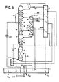
- air that has been compressed to about 638,2 kPa (6.3 ATA) is cleaned of H 2 O and CO 2 and is cooled in main heat exchanger 1 to near its dewpoint, and then introduced into LOXBOIL evaporator 2 where it is partially condensed.
- the uncondensed portion is fed to HP rectifier 3, which is refluxed by latent heat exchanger 4, located in the bottom of low pressure column 5.
- the LP column is comprised of three sections: argon stripper 6, argon rectifier 7, and N2 removal section 8, with all three having a common connection point 5.
- Liquid N 2 overhead product from 3 is routed via sensible heat exchanger 9 and pressure letdown valve 10 into the overhead of N 2 removal section 8 as reflux therefor. This may optionally be via phase separator 11.
- Oxygen enriched liquid bottom product (“kettle liquid”) from HP rectifier 3 and from LOX vaporizer 2 is also cooled and then letdown in pressure in valves 12 and 13 and fed to N 2 removal section 8. At least part of the kettle liquid may first be evaporated in latent heat exchanger 14, which provides reflux to argon rectifier 7. Crude argon is withdrawn overhead from that column; it may be withdrawn either as a liquid or vapor. In either case it would normally be increased in pressure and subjected to further purification.
- Process cooling/refrigeration may be provided by withdrawing part of the HP rectifier 3 overhead N 2 as vapor phase, partially warming it in the complex of main exchanger 1, and then work expanding it in expander 15 and exhausting it via the main exchangers.
- part of the supply air may be partially cooled and then work expanded to LP column pressure and fed to the N 2 removal section at the approximate height where liquid phase kettle liquid is introduced.
- the high purity liquid oxygen bottom product from the argon stripper is increased in pressure from about 152,0 kPa (1.5) to about 202,6 kPa (2 ATA) and is evaporated in LOX gasifier 2.
- the pressure increased may be accomplished via a pump 17 or may be simply due to a barometric leg when the heights are appropriate, in which case 17 may be a means to preclude reverse flow and/or an adsorber for hydrocarbon cleanup.
- the novelty of Figure 1 is comprised of latent heat exchanger 16, and particularly the locations/ intermediate heights of the two column sections it interconnects.
- Intermediate height means there is more than one theoretical stage of countercurrent vapor-liquid contact both above and below the height.
- Latent heat exchanger 16 accepts intermediate height vapor from argon rectifier 7, liquefies at least part of it, and returns the liquid to an intermediate height of argon rectifier 7, thereby providing intermediate reflux to the argon rectifier.
- intermediate height liquid from N 2 removal section 8 At the same time it accepts intermediate height liquid from N 2 removal section 8, at least partially evaporates it, and returns the vapor to an intermediate height of the N 2 removal section, thereby providing intermediate reboil to that section. It is desirable that the intermediate height of the N 2 removal section be below the height at which kettle liquid is introduced.
- latent heat exchanger 16 is illustrated as being physically located within section 8, it will be recognized that it could alternatively be physically located within section 7 or external to both sections.
- the only essential locations are those of the source and return point of the two fluids supplied it, which must be the respective intermediate heights disclosed.
- the argon rectifier intermediate height be at least 2 and more preferably 5 to 15 stages above the bottom.
- LOX vaporizer 18 differ from the previously described one, 2, in that only part of the supply air is furnished to it, which totally condenses, as opposed to the partial condensation in 2. This lowers somewhat the achievable LOX evaporation pressure, but provides a source of liquid air (21% 0 2 ) which can be used as intermediate reflux to either or both of the N 2 removal section 8 via letdown valve 20, and HP rectifier 3 via means for inducing one way flow 19 (i.e., a pump or a valve). With this intermediate reflux, somewhat less LN 2 reflux is necessary for full O 2 recovery.
- the increased argon recovery may require increased reflux from exchanger 14, which can adversely affect O 2 recovery.
- part of the supply air may be work expanded to an intermediate pressure in expander 24, and then condensed in latent heat exchanger 25, which provides intermediate reboil to N 2 removal section 8. This liquid air is then led down in pressure via valve 26 and supplied as intermediate reflux to section 8.
- Even greater refrigeration can be developed by expander 24 if the air supplied to it is initially further compressed in compressor 27, driven by expander 23. Thus no additional power input is required for this additional refrigeration output.
- the components 24,25,26, and 27 are optional and may be omitted. Particularly on large plants, where proportionately less refrigeration is required, full O 2 recovery may be obtainable without them. On the other hand, they may nonetheless be desirable since the additional refrigeration may be put to other desirable uses, such as allowing some liquid production or decreasing the size and cost of the main exchanger.
- the same beneficial effect that is provided by components 24, 25, and 26 using part of the supply air can also be accomplished using nitrogen from the overhead of HP rectifier 3 or from the discharge from exchanger 21.
- the nitrogen is partially work expanded in expander 24 in lieu of air, and then condensed in exchanger 25.
- the resulting liquid N 2 is then letdown in pressure in valve 26 and injected into the top of section 8, in lieu of an intermediate height.
- the only substantial difference is that the N 2 cannot be reduced in pressure as much as the air to achieve the desired condensing temperature.
- the various disclosed features will be useful singly or in combination in the production of lower purity O 2 as well as 99.5+%.
- the three latent heat exchangers 16,21 and 25 may be used singly or in combination in LOXBOIL plants based on either partial or total condensation of the supply air, or in plants having other means of gasifying the LOX, such as direct gasification in the LP column bottom or pumped LOX variations, as disclosed for example in U.S. Patent 4433989.
- the cleaning and drying means may be a front end treatment such as mol sieve (preferable) or any other conventional or suitable means such as reversing exchangers, regenerators and the like.
- the argon rectifier intermediate refluxer 21 which is described above as being supplied with LN 2 could alternatively be supplied with liquid air, e.g., part of that from total condensation LOX evaporator 18. In that event the subsequently evaporated air would be fed to the N 2 removal section after expansion.
- This alternative is generally not as advantageous as evaporating LN 2 , since for a given evaporation temperature the evaporated air will be at a lower pressure than evaporated N 2 removal section after expansion.
- the following operating conditions reflect results achievable in a flowsheet similar to figure 1 but with a total condensation LOX evaporator (i.e., component 18 vice 2).
- a total condensation LOX evaporator i.e., component 18 vice 2.
- One thousand gram-moles per second (“m") of air is compressed to about 638.2 kPa (6.3 ATA), and 870 m is cleaned and cooled to 101 K and 607.8 kPa (6 ATA).
- 283 m is routed to the total condensation LOX evaporator, producing 203 m oxygen plus 1 m argon mixture (99.5+% pure oxygen) at 212.7 kPa (2.1 ATA) and 98 K.
- 130 m of the air is expanded from 170 K and 613.9 kPa (6.1 ATA) 141.8 kPa (1.4 ATA) and 119 K, and fed to the N 2 removal section
- the remaining air 587 m, is directed into the base of HP rectifier 3, and rectified into two liquid products.
- the overhead product 323 m of LN 2 at about 98.4% purity is routed to the top of the N 2 removal section as reflux.
- the bottom product, 462 m of kettle liquid containing 34.6% 0 2 is split with 199 m being directly fed to the N 2 removal section via valve 12, and 263 m directed to overhead latent heat exchanger 14.
- the 283 m liquid air from LOX evaporator 18 is also split, with 198 m being fed to an intermediate height of HP rectifier 3, and the remaining 85 m being directed into N 2 removal section 8 as intermediate reflux therefor.
- 300.5 m of oxygen-argon vapor containing 6.6% argon is directed into the base of the argon rectifier 7, and 293.9 m liquid is returned at 4.7% argon concentration; the net argon product overhead is 6.6 m at 96% purity.
- approximately one-third of the reboil going up the argon rectifier is transferred to the N 2 removal section by intermediate latent heat exchanger 16.
- 1 m of oxygen product is withdrawn as liquid to prevent hydrocarbon buildup, and the remaining 788 m of waste N 2 is withdrawn from the overhead of N 2 removal section 8 which is at a pressure of 126.6 kPa (1.25 ATA).
- sensible heat exchanger merely signifies the primary source of the heat being transferred, and does not preclude the presence of other sources such as sensible heat.
- one possible embodiment of the present invention disclosure is wherein there is only a single overhead reflux of the argon rectifier, and wherein that reflux is obtained by directly exchanging latent heat between argon rectifier overhead vapor and N 2 removal section intermediate height liquid.
- the novelty resides in the further inclusion in the process of a) a refrigeration work expander which expands approximately 5 to 15% of the supply air or a corresponding amount of HP rectifier overhead vapor to approximately the LP column pressure; b) a means for pressurizing liquid oxygen LP column bottom product to above LP column bottom pressure and evaporating it by exchanging latent heat with a totally condensing minor fraction of supply air; and c) a means for splitting the liquid air into two streams and refluxing intermediate heights of both the HP rectifier and the N 2 removal section with the respective streams.
Landscapes
- Engineering & Computer Science (AREA)
- Physics & Mathematics (AREA)
- Mechanical Engineering (AREA)
- Thermal Sciences (AREA)
- General Engineering & Computer Science (AREA)
- Health & Medical Sciences (AREA)
- Emergency Medicine (AREA)
- Separation By Low-Temperature Treatments (AREA)
- Treating Waste Gases (AREA)
- Gas Separation By Absorption (AREA)
Claims (14)
Priority Applications (1)
| Application Number | Priority Date | Filing Date | Title |
|---|---|---|---|
| AT86903748T ATE58788T1 (de) | 1985-04-29 | 1986-04-29 | Erhoehte argonwiedergewinnung bei der luftdistillierung. |
Applications Claiming Priority (2)
| Application Number | Priority Date | Filing Date | Title |
|---|---|---|---|
| US06/728,264 US4670031A (en) | 1985-04-29 | 1985-04-29 | Increased argon recovery from air distillation |
| US728264 | 1985-04-29 |
Publications (3)
| Publication Number | Publication Date |
|---|---|
| EP0225911A1 EP0225911A1 (de) | 1987-06-24 |
| EP0225911A4 EP0225911A4 (de) | 1987-08-12 |
| EP0225911B1 true EP0225911B1 (de) | 1990-11-28 |
Family
ID=24926116
Family Applications (1)
| Application Number | Title | Priority Date | Filing Date |
|---|---|---|---|
| EP86903748A Expired - Lifetime EP0225911B1 (de) | 1985-04-29 | 1986-04-29 | Erhöhte argonwiedergewinnung bei der luftdistillierung |
Country Status (8)
| Country | Link |
|---|---|
| US (1) | US4670031A (de) |
| EP (1) | EP0225911B1 (de) |
| JP (1) | JPS62502701A (de) |
| KR (1) | KR930010595B1 (de) |
| AT (1) | ATE58788T1 (de) |
| AU (1) | AU582243B2 (de) |
| DE (1) | DE3675903D1 (de) |
| WO (1) | WO1986006462A1 (de) |
Families Citing this family (27)
| Publication number | Priority date | Publication date | Assignee | Title |
|---|---|---|---|---|
| US4817393A (en) * | 1986-04-18 | 1989-04-04 | Erickson Donald C | Companded total condensation loxboil air distillation |
| GB8622055D0 (en) * | 1986-09-12 | 1986-10-22 | Boc Group Plc | Air separation |
| US4777803A (en) * | 1986-12-24 | 1988-10-18 | Erickson Donald C | Air partial expansion refrigeration for cryogenic air separation |
| US4832719A (en) * | 1987-06-02 | 1989-05-23 | Erickson Donald C | Enhanced argon recovery from intermediate linboil |
| US4836836A (en) * | 1987-12-14 | 1989-06-06 | Air Products And Chemicals, Inc. | Separating argon/oxygen mixtures using a structured packing |
| USRE34038E (en) * | 1987-12-14 | 1992-08-25 | Air Products And Chemicals, Inc. | Separating argon/oxygen mixtures using a structured packing |
| US4871382A (en) * | 1987-12-14 | 1989-10-03 | Air Products And Chemicals, Inc. | Air separation process using packed columns for oxygen and argon recovery |
| US4817394A (en) * | 1988-02-02 | 1989-04-04 | Erickson Donald C | Optimized intermediate height reflux for multipressure air distillation |
| US4842625A (en) * | 1988-04-29 | 1989-06-27 | Air Products And Chemicals, Inc. | Control method to maximize argon recovery from cryogenic air separation units |
| US4854954A (en) * | 1988-05-17 | 1989-08-08 | Erickson Donald C | Rectifier liquid generated intermediate reflux for subambient cascades |
| US4936099A (en) * | 1989-05-19 | 1990-06-26 | Air Products And Chemicals, Inc. | Air separation process for the production of oxygen-rich and nitrogen-rich products |
| US5114449A (en) * | 1990-08-28 | 1992-05-19 | Air Products And Chemicals, Inc. | Enhanced recovery of argon from cryogenic air separation cycles |
| US5245831A (en) * | 1992-02-13 | 1993-09-21 | Air Products And Chemicals, Inc. | Single heat pump cycle for increased argon recovery |
| US5255524A (en) * | 1992-02-13 | 1993-10-26 | Air Products & Chemicals, Inc. | Dual heat pump cycles for increased argon recovery |
| US5255522A (en) * | 1992-02-13 | 1993-10-26 | Air Products And Chemicals, Inc. | Vaporization of liquid oxygen for increased argon recovery |
| US5305611A (en) * | 1992-10-23 | 1994-04-26 | Praxair Technology, Inc. | Cryogenic rectification system with thermally integrated argon column |
| US5365741A (en) * | 1993-05-13 | 1994-11-22 | Praxair Technology, Inc. | Cryogenic rectification system with liquid oxygen boiler |
| DE69525225T2 (de) * | 1994-11-24 | 2002-08-14 | The Boc Group Plc, Windlesham | Lufttrennung |
| GB9423955D0 (en) * | 1994-11-24 | 1995-01-11 | Boc Group Plc | Air seperation |
| DE19636306A1 (de) * | 1996-09-06 | 1998-02-05 | Linde Ag | Verfahren und Vorrichtung zur Gewinnung von Argon durch Tieftemperaturzerlegung von Luft |
| US5924307A (en) * | 1997-05-19 | 1999-07-20 | Praxair Technology, Inc. | Turbine/motor (generator) driven booster compressor |
| US6318120B1 (en) * | 2000-08-11 | 2001-11-20 | L'air Liquide Societe Anonyme Pour L'etude Et L'exploitation Des Procedes Georges Claude | Cryogenic distillation system for air separation |
| FR2854232A1 (fr) * | 2003-04-23 | 2004-10-29 | Air Liquide | Procede de distillation d'air pour produire de l'argon |
| US9279613B2 (en) * | 2010-03-19 | 2016-03-08 | Praxair Technology, Inc. | Air separation method and apparatus |
| US10337792B2 (en) | 2014-05-01 | 2019-07-02 | Praxair Technology, Inc. | System and method for production of argon by cryogenic rectification of air |
| US9291389B2 (en) | 2014-05-01 | 2016-03-22 | Praxair Technology, Inc. | System and method for production of argon by cryogenic rectification of air |
| US10082333B2 (en) | 2014-07-02 | 2018-09-25 | Praxair Technology, Inc. | Argon condensation system and method |
Family Cites Families (11)
| Publication number | Priority date | Publication date | Assignee | Title |
|---|---|---|---|---|
| US1607323A (en) * | 1925-07-11 | 1926-11-16 | Air Reduction | Separation of the constituents of ternary gaseous mixtures |
| US1619909A (en) * | 1925-10-15 | 1927-03-08 | Air Reduction | Separation of the constituents of ternary gaseous mixtures |
| US2316056A (en) * | 1939-08-26 | 1943-04-06 | Baufre William Lane De | Method and apparatus for rectifying fluid mixtures |
| US2934907A (en) * | 1954-08-17 | 1960-05-03 | Union Carbide Corp | High argon recovery using kettle top feed-top pinch principle |
| US3210951A (en) * | 1960-08-25 | 1965-10-12 | Air Prod & Chem | Method for low temperature separation of gaseous mixtures |
| FR2041701B1 (de) * | 1969-05-05 | 1974-02-01 | Air Liquide | |
| DE2557453C2 (de) * | 1975-12-19 | 1982-08-12 | Linde Ag, 6200 Wiesbaden | Verfahren zur Gewinnung von gasförmigem Sauerstoff |
| JPS5568571A (en) * | 1978-11-17 | 1980-05-23 | Hitachi Ltd | Method of recovering argon by super cold separation |
| US4605427A (en) * | 1983-03-31 | 1986-08-12 | Erickson Donald C | Cryogenic triple-pressure air separation with LP-to-MP latent-heat-exchange |
| US4582518A (en) * | 1984-09-26 | 1986-04-15 | Erickson Donald C | Nitrogen production by low energy distillation |
| GB8512562D0 (en) * | 1985-05-17 | 1985-06-19 | Boc Group Plc | Liquid-vapour contact method |
-
1985
- 1985-04-29 US US06/728,264 patent/US4670031A/en not_active Expired - Fee Related
-
1986
- 1986-04-29 KR KR1019860700947A patent/KR930010595B1/ko not_active Expired - Fee Related
- 1986-04-29 DE DE8686903748T patent/DE3675903D1/de not_active Expired - Lifetime
- 1986-04-29 AT AT86903748T patent/ATE58788T1/de active
- 1986-04-29 AU AU58178/86A patent/AU582243B2/en not_active Ceased
- 1986-04-29 JP JP61502771A patent/JPS62502701A/ja active Pending
- 1986-04-29 EP EP86903748A patent/EP0225911B1/de not_active Expired - Lifetime
- 1986-04-29 WO PCT/US1986/000949 patent/WO1986006462A1/en not_active Ceased
Also Published As
| Publication number | Publication date |
|---|---|
| KR930010595B1 (ko) | 1993-10-30 |
| DE3675903D1 (de) | 1991-01-10 |
| JPS62502701A (ja) | 1987-10-15 |
| EP0225911A4 (de) | 1987-08-12 |
| AU5817886A (en) | 1986-11-18 |
| ATE58788T1 (de) | 1990-12-15 |
| KR880700227A (ko) | 1988-02-20 |
| WO1986006462A1 (en) | 1986-11-06 |
| AU582243B2 (en) | 1989-03-16 |
| US4670031A (en) | 1987-06-02 |
| EP0225911A1 (de) | 1987-06-24 |
Similar Documents
| Publication | Publication Date | Title |
|---|---|---|
| EP0225911B1 (de) | Erhöhte argonwiedergewinnung bei der luftdistillierung | |
| US5582035A (en) | Air separation | |
| KR100291684B1 (ko) | 공기의분리방법 | |
| AU578311B2 (en) | Low energy high purity oxygen plus argon | |
| US5337570A (en) | Cryogenic rectification system for producing lower purity oxygen | |
| US5577394A (en) | Air separation | |
| JPH0789017B2 (ja) | 高圧窒素の製造方法及び装置 | |
| JPH102664A (ja) | 低純度及び高純度の酸素製品を製造する圧縮原料空気流の低温蒸留方法 | |
| US5582031A (en) | Air separation | |
| JPH08271141A (ja) | 空気の分離 | |
| JPH0694361A (ja) | 空気の分離 | |
| US5715706A (en) | Air separation | |
| US5868007A (en) | Air separation | |
| EP0318564B1 (de) | Argongewinnung durch zwischengeschaltetes aufkochen von flüssigem stickstoff | |
| US5878598A (en) | Air separation | |
| JPH01247981A (ja) | 空気を分離する方法及び装置 | |
| CA2196353C (en) | Single column cryogenic rectification system for lower purity oxygen production | |
| US5819556A (en) | Air separation | |
| US5862680A (en) | Air separation | |
| EP0831284B1 (de) | Lufttrennung | |
| US12209802B2 (en) | System and method for cryogenic air separation using four distillation columns including an intermediate pressure column | |
| US11959701B2 (en) | Air separation unit and method for production of high purity nitrogen product using a distillation column system with an intermediate pressure kettle column | |
| US5799508A (en) | Cryogenic air separation system with split kettle liquid | |
| US20240035741A1 (en) | Air separation unit and method for cryogenic separation of air using a distillation column system including an intermediate pressure kettle column |
Legal Events
| Date | Code | Title | Description |
|---|---|---|---|
| PUAI | Public reference made under article 153(3) epc to a published international application that has entered the european phase |
Free format text: ORIGINAL CODE: 0009012 |
|
| 17P | Request for examination filed |
Effective date: 19870217 |
|
| AK | Designated contracting states |
Kind code of ref document: A1 Designated state(s): AT BE DE FR GB IT LU NL SE |
|
| A4 | Supplementary search report drawn up and despatched |
Effective date: 19870812 |
|
| 17Q | First examination report despatched |
Effective date: 19880701 |
|
| GRAA | (expected) grant |
Free format text: ORIGINAL CODE: 0009210 |
|
| ITF | It: translation for a ep patent filed | ||
| AK | Designated contracting states |
Kind code of ref document: B1 Designated state(s): AT BE DE FR GB IT LU NL SE |
|
| REF | Corresponds to: |
Ref document number: 58788 Country of ref document: AT Date of ref document: 19901215 Kind code of ref document: T |
|
| REF | Corresponds to: |
Ref document number: 3675903 Country of ref document: DE Date of ref document: 19910110 |
|
| ET | Fr: translation filed | ||
| PGFP | Annual fee paid to national office [announced via postgrant information from national office to epo] |
Ref country code: SE Payment date: 19910422 Year of fee payment: 6 |
|
| PGFP | Annual fee paid to national office [announced via postgrant information from national office to epo] |
Ref country code: LU Payment date: 19910424 Year of fee payment: 6 Ref country code: AT Payment date: 19910424 Year of fee payment: 6 |
|
| ITTA | It: last paid annual fee | ||
| PLBE | No opposition filed within time limit |
Free format text: ORIGINAL CODE: 0009261 |
|
| STAA | Information on the status of an ep patent application or granted ep patent |
Free format text: STATUS: NO OPPOSITION FILED WITHIN TIME LIMIT |
|
| EPTA | Lu: last paid annual fee | ||
| 26N | No opposition filed | ||
| PGFP | Annual fee paid to national office [announced via postgrant information from national office to epo] |
Ref country code: GB Payment date: 19920407 Year of fee payment: 7 |
|
| PGFP | Annual fee paid to national office [announced via postgrant information from national office to epo] |
Ref country code: FR Payment date: 19920415 Year of fee payment: 7 |
|
| PG25 | Lapsed in a contracting state [announced via postgrant information from national office to epo] |
Ref country code: LU Free format text: LAPSE BECAUSE OF NON-PAYMENT OF DUE FEES Effective date: 19920429 Ref country code: AT Effective date: 19920429 |
|
| PG25 | Lapsed in a contracting state [announced via postgrant information from national office to epo] |
Ref country code: SE Effective date: 19920430 |
|
| PGFP | Annual fee paid to national office [announced via postgrant information from national office to epo] |
Ref country code: NL Payment date: 19920430 Year of fee payment: 7 Ref country code: DE Payment date: 19920430 Year of fee payment: 7 |
|
| PGFP | Annual fee paid to national office [announced via postgrant information from national office to epo] |
Ref country code: BE Payment date: 19920506 Year of fee payment: 7 |
|
| PG25 | Lapsed in a contracting state [announced via postgrant information from national office to epo] |
Ref country code: GB Effective date: 19930429 |
|
| PG25 | Lapsed in a contracting state [announced via postgrant information from national office to epo] |
Ref country code: BE Effective date: 19930430 |
|
| BERE | Be: lapsed |
Owner name: ERICKSON DONALD CHARLES Effective date: 19930430 |
|
| PG25 | Lapsed in a contracting state [announced via postgrant information from national office to epo] |
Ref country code: NL Effective date: 19931101 |
|
| NLV4 | Nl: lapsed or anulled due to non-payment of the annual fee | ||
| PG25 | Lapsed in a contracting state [announced via postgrant information from national office to epo] |
Ref country code: FR Effective date: 19931229 |
|
| PG25 | Lapsed in a contracting state [announced via postgrant information from national office to epo] |
Ref country code: DE Effective date: 19940101 |
|
| GBPC | Gb: european patent ceased through non-payment of renewal fee |
Effective date: 19930429 |
|
| REG | Reference to a national code |
Ref country code: FR Ref legal event code: ST |
|
| EUG | Se: european patent has lapsed |
Ref document number: 86903748.1 Effective date: 19921108 |
|
| PG25 | Lapsed in a contracting state [announced via postgrant information from national office to epo] |
Ref country code: IT Free format text: LAPSE BECAUSE OF NON-PAYMENT OF DUE FEES;WARNING: LAPSES OF ITALIAN PATENTS WITH EFFECTIVE DATE BEFORE 2007 MAY HAVE OCCURRED AT ANY TIME BEFORE 2007. THE CORRECT EFFECTIVE DATE MAY BE DIFFERENT FROM THE ONE RECORDED. Effective date: 20050429 |