EP0226025A2 - Procédé et appareil de fabrication de tubes à ailettes - Google Patents
Procédé et appareil de fabrication de tubes à ailettes Download PDFInfo
- Publication number
- EP0226025A2 EP0226025A2 EP86115385A EP86115385A EP0226025A2 EP 0226025 A2 EP0226025 A2 EP 0226025A2 EP 86115385 A EP86115385 A EP 86115385A EP 86115385 A EP86115385 A EP 86115385A EP 0226025 A2 EP0226025 A2 EP 0226025A2
- Authority
- EP
- European Patent Office
- Prior art keywords
- tube
- fact
- tool
- cutting
- supporting
- Prior art date
- Legal status (The legal status is an assumption and is not a legal conclusion. Google has not performed a legal analysis and makes no representation as to the accuracy of the status listed.)
- Withdrawn
Links
Images


Classifications
-
- B—PERFORMING OPERATIONS; TRANSPORTING
- B21—MECHANICAL METAL-WORKING WITHOUT ESSENTIALLY REMOVING MATERIAL; PUNCHING METAL
- B21C—MANUFACTURE OF METAL SHEETS, WIRE, RODS, TUBES, PROFILES OR LIKE SEMI-MANUFACTURED PRODUCTS OTHERWISE THAN BY ROLLING; AUXILIARY OPERATIONS USED IN CONNECTION WITH METAL-WORKING WITHOUT ESSENTIALLY REMOVING MATERIAL
- B21C37/00—Manufacture of metal sheets, rods, wire, tubes, profiles or like semi-manufactured products, not otherwise provided for; Manufacture of tubes of special shape
- B21C37/06—Manufacture of metal sheets, rods, wire, tubes, profiles or like semi-manufactured products, not otherwise provided for; Manufacture of tubes of special shape of tubes or metal hoses; Combined procedures for making tubes, e.g. for making multi-wall tubes
- B21C37/15—Making tubes of special shape; Making tube fittings
- B21C37/20—Making helical or similar guides in or on tubes without removing material, e.g. by drawing same over mandrels, by pushing same through dies ; Making tubes with angled walls, ribbed tubes or tubes with decorated walls
- B21C37/207—Making helical or similar guides in or on tubes without removing material, e.g. by drawing same over mandrels, by pushing same through dies ; Making tubes with angled walls, ribbed tubes or tubes with decorated walls with helical guides
Definitions
- the finned tubes for heat exchangers known at present can be divided into two main categories: those having inserted fins and those having fins integral with the tube.
- the finned tubes of the first category are made either by winding a strip of sheet metal in spiral-fashion around a plain cylindrical tube, said strip being made of the same material as the tube or of other material, or by fitting a set of evenly spaced apart metal plates of annular shape over the tube.
- the fin in which the fin consists of a thin metal plate, even though it is fitted tightly onto the tube, contact between the tube and the fin is not made over the entire theoretical fitting surface, but only in a few places; the rest of the fin either does not make contact, or makes contact by means of the film of oxides and/or foreign substances which are generally poor conductors and with which both the fin and the tube are covered.
- the tubes of the second category in which the fin is made in one piece with the tube by a process in which the fin is extruded and pressed from the ductile material of the tube in the grooves of a die, until it protrudes in the form of a fin, present the drawback that the fins cannot be made very thin, as is possible with inserted fins, and consequently the cost of the material required for manufacturing them comes to bear heavily upon the cost of the product.
- the finned tubes may be made relatively short in size and, nonetheless, the finning operation which also involves inserting and removing the bar from the tubes, proves to be complex and therefore detrimental to the economic advantage of producing such tubes.
- the internal surface of the tube becomes corrugated and scored in correspondence with the fins, that is to say, crosswise to the direction of flow of the fluid in the tube, with a consequent increase in the resistance of the duct.
- the present invention refers to a method for manufacturing finned tubes having fins made integral with the tube, but obtained by means of a cheaper and simpler system than those mentioned above, with the possibility of obtaining thinner fin thicknesses, with thin-walled tubes, and consequently with a higher heat exchange coefficient.
- the method referred to in this invention starts from a plain cylindrical tube of adequate thickness and a suitably-shaped and positioned cutting tool provided with relative movement with respect to the tube to enable it to cut and shape, from the tube itself, thin fins arranged in spiral fashion around its outer surface.
- leading edge the cutting portion of the tool which, during the cutting operation, is the first part to encounter the surface of the tube and to make the cut
- trailing edge the portion of the tool which, during the cutting operation, is the last part to lose contact with the material of the tube
- the tool will make a circular incision on the tube, with a certain accumulation of material on either side of the cut, due to plastic deformation.
- the leading edge lies in a sloping plane crossing the axis of the tube according to a cutting line not in the same plane and forming angle smaller than 90° with respect to the generating lines of the tube and with the same relative motion around the axis of the tube, but that the trailing or rib-bending edge no longer coincides with it, but lies in a plane considerably perpendicular to the axis of the tube and is radiused with the leading edge; let us also assume that, in correspondence with the trailing edge or line of abandonment of contact with the rib, the tool is provided with a surface, even though rather small, whose points are provided with relative speeds directed tangentially both to the surface of the tool and to the lateral surface of the rib, in the points of contact, then between such surface and the corresponding contact surface of the rib, there will not be any interference, but a relative slow sliding motion.
- the rib initially raised by the leading edge will not be cut off by the trailing edge, but will be bent by the latter in a plane substantially perpendicular to the tube, while remaining integrally anchored to it.
- a helical fin will be formed on the latter.
- the finning or rib described above can be made in practice by giving the tube a rotatory movement with respect to its axis and by giving the tool a rectilinear movement parallel to the axis of the tube, in the direction of the non-finned portion of the tube, with a sufficient speed to ensure that the rectilinear displacements of the tool, for each turn of the tube, are the same as the desired pitch of the fin, which will be disposed around the tube according to a cylindrical spiral.
- the portion of surface adjacent to the trailing edge of the cutter, which comes into contact with the rib last, will be disposed and shaped according to the planes tangent to the surface of the cylindrical helicoid of the fin which is to be made.
- a first solution to this problem consists in providing an apparatus equipped with a support for the tube to be finned, positioned close to the tool, which, during the operation, reacts with a pressure identical and contrary to the action of the tool on the tube, without allowing excessive strain and, simultaneously, enables the tube to slide axially and rotate in said support.
- an embodiment of such support consists of a bushing, if necessary made of special, hard or anti-friction material, fitted and secured in a special housing, fixed to the tool-holder structure.
- said tube supporting bushing can be arranged in correspondence with the cylindrical portion of the tube, not yet finned, and the tool can be supported so that the rectilinear movement of the tool is directed towards such bushing.
- said bushing can be fitted to rotate in a support consisting of a roller bearing or can consist of the inner ring of the bearing itself; moreover, said support may not necessarily consist of a complete ring, but may also just consist of one or more parts of it, provided that it is capable of supporting the tube subjected to the thrust of the tool, which otherwise would distort it.
- a further embodiment of the function of the aforesaid bushing, namely the support for the tube, may consist of a structure disposed around the tube, close to the tool, upon which are secured, if necessary in an adjustable position, one or more backup or thrust rollers which, during the finning operation, are disposed and positioned around the tube, so as to prevent any lateral displacement.
- a further embodiment of the invention for achieving a valid support and positioning for the tube consists in using two or more tools, disposed symmetrically with respect to the tube and spaced angularly apart from each other in such a way that their actions upon the tube cancel each other out.
- the second case namely in which the tools are provided with rotatory motion and the tube with rectilinear motion, is more suitable for finning even very long tubes.
- reference l indicates the originally smooth tube which is made to rotate in the direction of the arrow A by a motor means 2, shown schematically in the drawing, which also has the task of helping to keep the axis of the tube in a steady position during its rotation.
- Reference 3 indicates a cutting and finning tool, supported and locked by means of a fastening member or clamp 4 whose upper jaw 4a locks the tool 3 in a seat in the lower jaw 4b by means of a securing screw 5.
- the clamp 4 can be made to slide or move along the guide 6 by means of a servo control 8a such as a piston, cam or other control device capable of shifting the tool 3 close to the tube l and of positioning it in the exact working position, or of shifting it away from the tube according to movements indicated respectively by the arrows C and C′.
- a servo control 8a such as a piston, cam or other control device capable of shifting the tool 3 close to the tube l and of positioning it in the exact working position, or of shifting it away from the tube according to movements indicated respectively by the arrows C and C′.
- the cross guide 6 is provided on a slide 7 running along a longitudinal guide 7a by which it is possible to move the tool 3 with rectilinear motion in the direction of the arrow B, driven by any type of actuating means 8b, such as for example, a hydraulic or pneumatic cylinder, worm screw, chain or other equivalent drive means.
- actuating means 8b such as for example, a hydraulic or pneumatic cylinder, worm screw, chain or other equivalent drive means.
- a device 9, integral and movable with the slide 7, is provided for centering and supporting the tube l, said device being provided, in an appropriate position close to the tool 3, with a fixed or rotating cylindrical bushing l0 havIng its axis coinciding with that of the tube l to be finned which crosses it, with the possibility of sliding and rotating.
- the cutting tool 3 presents a first cutting edge 3a, also referred to as leading edge due to the fact that it is the first to encounter the surface of the tube l to be cut, and a second edge 3b, also referred to as trailing edge due to the fact that, during the cutting operation, it is the last to lose contact with the material of the tube, which is radiused to the leading edge 3a as shown.
- the leading edge 3a which makes the cut along a helical line in the wall of the tube l, lies in a slanting plane crossing the axis of the tube l whose cutting line is oblique and forms an angle of less than 90° with the generating lines of the outer surface of the tube itself, so as to allow an action of cutting the wall of the tube, and an action of raising a continuous strip which will then be bent and folded outwards to the side to form a continuous helical fin ll on the outer surface of the tube itself.
- the trailing edge 3b of the cutting tool 3 lies in a plane substantially at right angles to the axis of the tube l and, in correspondence with the area merging with the leading edge 3a, in which the tool loses contact with the fin ll, presents a surface 3c directed tangentially to the lateral surface of the fin ll; thus, during the relative movement between the tool 3 and the fin ll, their points of contact close to the trailing edge 3b will have relative speeds directed tangentially both to the surface of the fin and to the cutting tool itself, thus giving rise to a plane sliding movement between the contacting surfaces which eliminates any interference whatsoever, allows the rib to be bent correctly and raised to form the helical fin.
- the device of fig. l for forming a helical fin ll on the tube l operates as follows:
- the tube l is set in uniform rotatory motion, with a constant speed of rotation in the direction of the arrow A, and the slide 7 is made to move with a uniform rectilinear motion in the direction of the arrow B, and if immediately after the control device which causes the clamp 4 supporting the tool 3 to move in the direction C is put into operation and then stopped in the working position, the tool due to its particular conformation, will run with its cutting edge 3a around the surface of the tube l, thus creating a helical-shaped shaving or rib which remains integral with the latter at the base and anchored to the wall of the tube, and which is then bent and raised to form the fin ll.
- the pitch p of the fin ll will depend upon the ratio between the traversing speed of the tool and the peripheral speed of rotation of the tube.
- an embodiment of the invention is also indicated in figure l, by taking into account the part in dotted lines in which the pressure exerted by the tool 3 on the tube is balanced by a second tool 3′, held by a clamp 4′ on a slide identical or similar to the one supporting the tool 3 so that the actions of the tools 3 and 3′ are, as far as possible, equal and opposing.
- the leading edge of the tool 3′ will be situated, with respect to the tool 3, further along the axis of the tube by a distance equal to half the pitch p .
- the tools will be arranged at l20° from one another, in perpendicular planes to the axis of the tube, and their leading edges will be shifted, along the axis of the tube, by a third of a pitch p .
- the described equipment may present a tool for automatically cutting the finned tube into tubular sections of a pre-established length; said tool, as in the case of the finning tools, is mounted on a slide movable in a crosswise direction to the tube, driven by control means and mechanical, hydraulic and/or pneumatic servomechanisms controlled by sensing means whose position can be varied and adjusted according to specific requirements.
- the tube centering member l0 mounted on the support 9, integral with the tool-holding slide 7, is indicated for the sake of simplicity simply as a bushing, however, without deviating from the sphere of this invention, it can be made in numerous different ways provided that they are capable of keeping the tube centered and of counteracting the thrust of the finning tool 3, and at the same time allowing the tube to slide freely.
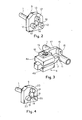
- the tube supporting and positioning device could be made as shown in figures 2, 3 and 4.
- the backup rollers l3 can be disposed with their axes parallel to the axis of the tube, or with their axes perpendicular to the cylindrical spiral in the points of contact of the rollers with the tube itself, in order to obtain as little slip as possible between the rollers and the tube.
- Fig. 2 shows three rollers, however, there may be any number of them; moreover, without deviating from the sphere of this invention, the pin l2 of the backup rollers l3 may either be in a fixed position with respect to the supporting plate 9 or movable and positionable at will, to enable tubes of different diameters to be machined or, if necessary, for taking up slack.
- FIG. 3 shows a single idle backup roller l5 supported by a pin l6 in a fixed position, or adjustable by means of a supporting arm l7 having a slot l8 penetrated by a bolt l9 by means of which the arm l7 can be secured to the tool-supporting clamp 4 in such a way that the tube centering device can also move forward and position itself at the same time as the tool at the beginning of the tube-cutting operation.
- FIG. 4 A further embodiment of the centering device is shown in fig. 4, where the plate 9 around the hole l4 for the tube l is provided with three angularly spaced apart fixed backup elements 20 having rigid surfaces 2l destined to come into contact with the tube l to be finned and to hold it in position by counteracting the thrust of the tool and of the finning tools 3, 3′.
- Said backup surfaces 2l may be made of special, hard or anti-friction materials constituting the backup elements 20, or of inserts.
- the latter will be moved in an axial direction by a drive system commonly used for rectilinear movements of this type, whereas the tool or tools will be disposed on a head revolving around an axis coinciding with the axis of the tube.
- Figs. 5, 6 and 7 show, by way of a non-restrictive example, several embodiments of these mem bers according to this invention, for the type of machine with a tube provided with rectilinear motion and tools provided with rotatory motion.
- fig. 5 shows one of the possible embodiments of a rotatory tool-holding device, consisting of an annular head 25 provided with angularly spaced apart radial guides 26, in which supports 27 slide; the tools 3, together with all the regulating and drive members previously described being secured to said supports 27.
- Said head 25 defines a hole 28 with a larger diameter than the tube l, and is supported to rotate around an axis coinciding with the axis of the tube l by means of rolling bearings or bushings housed in the supporting block 29 comprising means for guiding the tube itself.
- Said head 25 receives its rotatory movement from a usual driving means (not shown) and may comprise, in particular, all the devices for automatically positioning the tools 3 close to the tube l, for the beginning and end of the finning operation.
- the slides 27 of the head 25 can be provided with devices for centering the tube similar to those described for the apparatus with the ro tating tube.
- the solution of fig. 6 shows a device for feeding the tube l by means of a series of pairs of opposing splined rollers 22, 22′ which are made to rotate with constant speed by any type of mechanical drive system.
- the solution of fig. 7 shows another system for feeding the tube obtained by means of one or more pairs of endless conveyor chains or belts 23, 23′ provided at pre-established intervals with pads 24, 24′ shaped according to the shape of the tube l.
Landscapes
- Engineering & Computer Science (AREA)
- Mechanical Engineering (AREA)
Applications Claiming Priority (2)
| Application Number | Priority Date | Filing Date | Title |
|---|---|---|---|
| IT2279885 | 1985-11-12 | ||
| IT8522798A IT1215315B (it) | 1985-11-12 | 1985-11-12 | Metodo di fabbricazione di tubi alettati ad alto coefficiente di scambio termico e tubi alettati ottenuti con tale metodo. |
Publications (2)
| Publication Number | Publication Date |
|---|---|
| EP0226025A2 true EP0226025A2 (fr) | 1987-06-24 |
| EP0226025A3 EP0226025A3 (fr) | 1988-08-31 |
Family
ID=11200543
Family Applications (1)
| Application Number | Title | Priority Date | Filing Date |
|---|---|---|---|
| EP86115385A Withdrawn EP0226025A3 (fr) | 1985-11-12 | 1986-11-06 | Procédé et appareil de fabrication de tubes à ailettes |
Country Status (2)
| Country | Link |
|---|---|
| EP (1) | EP0226025A3 (fr) |
| IT (1) | IT1215315B (fr) |
Cited By (2)
| Publication number | Priority date | Publication date | Assignee | Title |
|---|---|---|---|---|
| GB2218359A (en) * | 1988-05-13 | 1989-11-15 | Mars Di Renzo Giovanni Tomezzo | Manufacturing finned tubes |
| KR100653635B1 (ko) | 2005-01-06 | 2006-12-05 | 김상선 | 열교환기용 핀튜브 성형장치 |
Family Cites Families (6)
| Publication number | Priority date | Publication date | Assignee | Title |
|---|---|---|---|---|
| US2661526A (en) * | 1944-01-26 | 1953-12-08 | Griscom Russell Co | Method of making fin tubing |
| GB1097519A (en) * | 1965-01-13 | 1968-01-03 | Giorgio Palloni | Method for the production of finned pipes for heat exchanger apparatus |
| GB1150525A (en) * | 1967-07-11 | 1969-04-30 | Acme Cleveland Corp | Method and Machine for Form Rolling |
| US3727682A (en) * | 1970-02-24 | 1973-04-17 | Peerless Of America | Heat exchangers and the method of making the same |
| US3800580A (en) * | 1973-01-08 | 1974-04-02 | Armco Steel Corp | Thread rolling apparatus |
| IT1212616B (it) * | 1982-11-04 | 1989-11-30 | Scoti Alberto | Procedimento per ricavare alettature integrali su superfici piane o curve mediante sfogliatura ottenuta con azione combinata di taglio e piegatura |
-
1985
- 1985-11-12 IT IT8522798A patent/IT1215315B/it active
-
1986
- 1986-11-06 EP EP86115385A patent/EP0226025A3/fr not_active Withdrawn
Cited By (4)
| Publication number | Priority date | Publication date | Assignee | Title |
|---|---|---|---|---|
| GB2218359A (en) * | 1988-05-13 | 1989-11-15 | Mars Di Renzo Giovanni Tomezzo | Manufacturing finned tubes |
| FR2631269A1 (fr) * | 1988-05-13 | 1989-11-17 | Mars Di Renzo Giovanni Tomezzo | Procede de fabrication de tubes a ailettes a coefficient d'echange thermique eleve |
| GB2218359B (en) * | 1988-05-13 | 1992-10-21 | Mars Di Renzo Giovanni Tomezzo | A method of manufacturing finned tubes having a high heat exchange factor. |
| KR100653635B1 (ko) | 2005-01-06 | 2006-12-05 | 김상선 | 열교환기용 핀튜브 성형장치 |
Also Published As
| Publication number | Publication date |
|---|---|
| EP0226025A3 (fr) | 1988-08-31 |
| IT1215315B (it) | 1990-01-31 |
| IT8522798A0 (it) | 1985-11-12 |
Similar Documents
| Publication | Publication Date | Title |
|---|---|---|
| US6381843B1 (en) | Method of producing a catalytic converter | |
| JP2957154B2 (ja) | 管端の成形方法とその装置 | |
| EP0565772B1 (fr) | Cage de laminoir à trois cylindres actionnés et ajustables | |
| EP2123372B1 (fr) | Procédé pour plier des tuyaux, tiges, sections profilées et éléments similaires et dispositif correspondant | |
| EP1017515B1 (fr) | Procede et appareil de traitement par filage | |
| US5615570A (en) | Method for bending a pipe and apparatus for bending the same | |
| EP1151812B1 (fr) | Dispositif de fluotournage | |
| KR20040111346A (ko) | 다양한 직경의 생산품을 만들기 위한 방법 및 성형기 | |
| JPH07164382A (ja) | 波形及びツインウォールパイプに溝孔を切るための装置 | |
| US3475938A (en) | Apparatus for bending | |
| JP2000190030A (ja) | 管素材の端部成形方法及び装置 | |
| US4287743A (en) | Method and device for the manufacture of helical rotor blanks for helical gear machines | |
| EP1380365A1 (fr) | Mecanisme de broche | |
| US6233991B1 (en) | Apparatus and method for spin forming a tube | |
| EP0226025A2 (fr) | Procédé et appareil de fabrication de tubes à ailettes | |
| KR20030087623A (ko) | 중공 공작물을 변형시키기 위한 방법 및 성형기 | |
| JP2000190038A (ja) | 管素材の端部成形方法及び装置 | |
| US4094178A (en) | Methods for continuous extrusion | |
| PL200911B1 (pl) | Sposób integralnego formowania kołnierza lub obrzeża na zakończeniu rury z blachy i urządzenie do integralnego formowania kołnierza lub obrzeża na zakończeniu rury z blachy | |
| CN115570550A (zh) | 一种法兰加工用定位翻转装置 | |
| JPH0685944B2 (ja) | コルゲ−トパイプ製造装置 | |
| US4339936A (en) | Annular corrugator | |
| JP4472071B2 (ja) | 絞り加工装置 | |
| RU217763U1 (ru) | Устройство клети для изготовления труб с многозаходными винтовыми гофрами | |
| CN113172126B (zh) | 扁带折弯设备及扁带折弯方法 |
Legal Events
| Date | Code | Title | Description |
|---|---|---|---|
| PUAI | Public reference made under article 153(3) epc to a published international application that has entered the european phase |
Free format text: ORIGINAL CODE: 0009012 |
|
| AK | Designated contracting states |
Kind code of ref document: A2 Designated state(s): DE ES FR GB NL SE |
|
| PUAL | Search report despatched |
Free format text: ORIGINAL CODE: 0009013 |
|
| AK | Designated contracting states |
Kind code of ref document: A3 Designated state(s): DE ES FR GB NL SE |
|
| 17P | Request for examination filed |
Effective date: 19890204 |
|
| 17Q | First examination report despatched |
Effective date: 19890726 |
|
| STAA | Information on the status of an ep patent application or granted ep patent |
Free format text: STATUS: THE APPLICATION IS DEEMED TO BE WITHDRAWN |
|
| 18D | Application deemed to be withdrawn |
Effective date: 19900602 |