EP0226026A2 - Automatische Justiereinrichtungskorrektur in Flugzeugen - Google Patents
Automatische Justiereinrichtungskorrektur in Flugzeugen Download PDFInfo
- Publication number
- EP0226026A2 EP0226026A2 EP86115391A EP86115391A EP0226026A2 EP 0226026 A2 EP0226026 A2 EP 0226026A2 EP 86115391 A EP86115391 A EP 86115391A EP 86115391 A EP86115391 A EP 86115391A EP 0226026 A2 EP0226026 A2 EP 0226026A2
- Authority
- EP
- European Patent Office
- Prior art keywords
- boresight
- positions
- aircraft
- symbol
- instantaneous
- Prior art date
- Legal status (The legal status is an assumption and is not a legal conclusion. Google has not performed a legal analysis and makes no representation as to the accuracy of the status listed.)
- Ceased
Links
- 238000012937 correction Methods 0.000 title claims abstract description 41
- 230000015654 memory Effects 0.000 claims abstract description 49
- 238000000034 method Methods 0.000 claims description 48
- 238000012545 processing Methods 0.000 claims description 28
- 239000013598 vector Substances 0.000 claims description 21
- 238000010304 firing Methods 0.000 claims description 13
- 238000012935 Averaging Methods 0.000 claims description 4
- 239000000700 radioactive tracer Substances 0.000 claims description 4
- 238000001514 detection method Methods 0.000 claims 1
- 238000010586 diagram Methods 0.000 description 12
- 238000004364 calculation method Methods 0.000 description 10
- 230000003287 optical effect Effects 0.000 description 4
- 238000012360 testing method Methods 0.000 description 3
- 239000011159 matrix material Substances 0.000 description 2
- 230000001133 acceleration Effects 0.000 description 1
- 238000013459 approach Methods 0.000 description 1
- 238000005452 bending Methods 0.000 description 1
- 230000007123 defense Effects 0.000 description 1
- 230000006870 function Effects 0.000 description 1
- 239000011521 glass Substances 0.000 description 1
- 238000004519 manufacturing process Methods 0.000 description 1
- 239000000463 material Substances 0.000 description 1
- 239000000523 sample Substances 0.000 description 1
- 238000000926 separation method Methods 0.000 description 1
- 238000001228 spectrum Methods 0.000 description 1
- 238000012549 training Methods 0.000 description 1
Images


Classifications
-
- F—MECHANICAL ENGINEERING; LIGHTING; HEATING; WEAPONS; BLASTING
- F41—WEAPONS
- F41G—WEAPON SIGHTS; AIMING
- F41G11/00—Details of sighting or aiming apparatus; Accessories
-
- F—MECHANICAL ENGINEERING; LIGHTING; HEATING; WEAPONS; BLASTING
- F41—WEAPONS
- F41G—WEAPON SIGHTS; AIMING
- F41G3/00—Aiming or laying means
- F41G3/32—Devices for testing or checking
- F41G3/323—Devices for testing or checking for checking the angle between the muzzle axis of the gun and a reference axis, e.g. the axis of the associated sighting device
-
- F—MECHANICAL ENGINEERING; LIGHTING; HEATING; WEAPONS; BLASTING
- F41—WEAPONS
- F41G—WEAPON SIGHTS; AIMING
- F41G3/00—Aiming or laying means
- F41G3/14—Indirect aiming means
- F41G3/142—Indirect aiming means based on observation of a first shoot; using a simulated shoot
-
- F—MECHANICAL ENGINEERING; LIGHTING; HEATING; WEAPONS; BLASTING
- F41—WEAPONS
- F41G—WEAPON SIGHTS; AIMING
- F41G3/00—Aiming or laying means
- F41G3/22—Aiming or laying means for vehicle-borne armament, e.g. on aircraft
-
- F—MECHANICAL ENGINEERING; LIGHTING; HEATING; WEAPONS; BLASTING
- F41—WEAPONS
- F41G—WEAPON SIGHTS; AIMING
- F41G5/00—Elevating or traversing control systems for guns
- F41G5/14—Elevating or traversing control systems for guns for vehicle-borne guns
- F41G5/18—Tracking systems for guns on aircraft
Definitions
- This invention relates to aircraft gunnery boresight correction, and more particularly, to a system for effecting such gunnery boresight correction in an aircraft, automatically, upon the firing of several rounds of bullets, and while in flight, if so desired.
- a tracking radar is of little value, however, as a bullet sensor on a fighter aircraft where the primary target sensor is the pilot looking through a head-up display (HUD). It is essential, in this case, that the error between the HUD sighting or aiming reference and the observed bullets be measured in the visible, or near visible, portion of the electromagnetic spectrum.
- HUD head-up display
- an automatic aircraft gunnery boresight correction system for use in an aircraft having a gunnery system and a sighting system therefor. Included are a cockpit television camera for detecting the location at a given instant of bullets fired from the gunnery system and a head-up display (HUD) for displaying through the sighting system a boresight symbol representing a reference point from which the predicted instantaneous position of fired bullets is computed.
- a display processor is provided and includes a video processing section for extracting the relative positions of fired bullets and the boresight symbol from the camera signal and storing data representing the positions of both.
- the display processor further includes a digital processor which calculates a predicted trajectory or series of instantaneous positions which the fired bullets will take.
- the digital processor also computes the difference or error between the observed positions of the fired bullets and the predicted positions thereof.
- a corrected boresight position is calculated and the digital processor includes a non-volatile memory for storing the corrected boresight position.
- the digital processor is adapted to correct the aircraft sighting system according to the corrected boresight position.
- the automatic boresight correction (ABC) system is activated when the aircraft pilot selects the system with a mode selector switch. At that time, the digital processor branches to the appropriate software stored in a program memory within the digital processor. The pilot performs a sequence of aircraft maneuvers in conjunction with firing bullets and a corrected boresight symbol is computed in the digital processor.
- a method for boresighting a gunnery system in an aircraft having a sighting system including a boresight symbol includes the steps of: firing several rounds from the gunnery system; predicting the position of the fired rounds relative to the boresight symbol; computing the actual positions of the fired rounds; computing an error vector between the predicted positions and the actual positions of the fired rounds; and correcting the sighting system to compensate for the error according to the error vector.
- a method for automatically boresighting a gunnery system in an aircraft having a sighting system including a boresight symbol including the following steps: firing several rounds from the gunnery system; predicting the trajectory of the fired rounds relative to the boresight symbol; determining the actual trajectory of the fired rounds; computing the error vector between the predicted trajectory and the actual trajectory of the fired rounds; and correcting the sighting system to compensate for the error according to the error vector.
- a method for automatically boresighting a gunnery system in an aircraft having a sighting system including a boresight symbol including performing two constant turn maneuvers and for each maneuver performing the following steps: firing several rounds from the gunnery system; determining the actual trajectory of the fired rounds; determining the best straight line of the trajectory (by averaging the bullet position centroid over a number of frames); then after the completion of the second maneuver solving the best straight lines for their instantaneous solution, that solution being the actual position of the aircraft boresight; and correcting the sighting system by replacing the previous boresight position with this new boresight position.
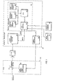
- FIG. 1 of the drawing there is shown in block diagram form the preferred embodiment of the automatic aircraft gunnery boresight correction system for use in an aircraft having a gunnery system and a sighting system therefor.
- a cockpit television sensor or camera, CTVS, 10 is provided for detecting the locations at a given instant of bullets fired from the gunnery system.
- a head-up display, HU D 20 is provided for displaying an aiming or boresight symbol representing a sighting reference point from which the predicted instantaneous positions of fired bullets is computed.
- H UD 20 includes a combining glass 22 and HUD optics and electronics 24.
- the boresight symbol is generated in a display processor 30 by a symbol generator 32 which provides the input signal for HUD optics and electronics 24.
- the positioning of the boresight symbol is controlled by a digital processor 35, also contained within display processor 30.
- a video processing section 36 is provided for extracting and storing data representing the positions of the fired bullets and the boresight symbol and is also part of display processor 30.
- Digital processor 35 includes software for predicting a sequence of instantaneous points forming a path which the fired bullets will take. A system for predicting such a path is described in U.S. Patent 4,308,015 to Tye, which is herein incorporated by reference.
- Digital processor 35 has a central processing unit, CPU 34, an input/output ( 1/ 0) control 37, and also includes a scratch pad memory 33, a non-volatile memory 39, and a program memory 38.
- Program memory 38 includes software for determining the difference or relative error between the observed positions of the fired bullets and the predicted positions thereof.
- a corrected boresight position, determined from the calculated error is stored in non-volatile memory 39. In a preferred embodiment, the corrected boresight position is used in weapon delivery calculations to correct the sighting system. Alternatively, the calculated error could be used in weapon delivery calculations.
- the circuit of Figure 1 operates as follows.
- the pilot selects the automatic boresight correction system on a mode selector switch 42, makes a turning maneuver and fires a short burst, preferably of tracer rounds.
- the burst is sensed by CTVS 10 and the fired bullets are tracked by the firmware of video processing section 36. Details of video processing section 36 are shown in Figures 2 and 3 and will be described hereinafter.
- a sighting system without the automatic boresight correction of the present invention normally includes HUD 20, digital processor 35 and symbol generator 32, without non-volatile memory 39 and relative error calculation software in program memory 38.
- the elements of the sighting system function together to allow the pilot to visually aim at targets through HUD 20, using symbology generated by symbol generator 32, and manipulated by signals from CPU 34 using weapon delivery processing software in program memory 38.
- These manipulations take into account data received from a plurality aircraft motion sensors 40. This motion data reflects the instantaneous physical conditions of the aircraft at the time of firing, including the rates of aircraft roll, pitch and yaw, the aircraft lift acceleration, true aircraft airspeed, gun angle of attack, and relative air density.
- CTVS 10 employs raster scan techniques to generate the electronic signals (video) representing the images the observer sees through HUD 20.
- the raster scan technique easily lends itself to matrix (X, Y) addressing of every point within the CTVS's field-of-view, every detected object within the image can be located by a matrix address. Therefore, cross 440 and all the objects seen by CTVS 10, including the bullets, can be assigned an address. Further, this address can represent positions, and as these positions will represent the positions of the objects, the system now has a means to measure (quantize) and compute positions, and positional differences between objects and symbols the camera sees.
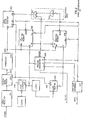
- FIG. 2 a block diagram is shown of the preferred embodiment implementation of video processing section 36 which contains the hardware to detect the presence of the objects the camera sees by determining if the input camera video signal exceeds a preset threshold level.
- Video signals from CTVS 10 are referenced to a DC voltage in a video receiver 201 to allow the separation of the horizontal and vertical synchronizing pulses (HSP and VSP) from the picture video in a sync separator 202.
- a picture video signal 203 is passed to a threshold circuit 204 where only video signals greater than a set threshold value are allowed to produce a threshold video pulse 205.
- the VSP and HSP condition a line counter 206 and a pixel counter 207, respectively, to allow a unique identification, or address, of each pixel within the video frame.
- the resolution of the address will be determined by the frequency of the clock generator.
- the values of the line and pixel counter contents are stored in a Y position memory 208 and an X position memory 209, respectively, at their Di inputs.
- an electronic window or tracker gate 550 shown in Figure 5, is formed about the predicted bullet positions, of sufficient width and height to encompass any positional errors, by a window generator 240 .
- Window generator 240 generates window boundaries with data from program memory 38 (of Figure 1) and will allow only line counter values and pixel counter values that are within these bounds to be entered into memories 208 and 209. The position of the window is continuously computed during the gunnery interval to follow the path of the bullets.
- a video pulse counter 210 is advanced by each threshold video pulse 205.
- the output of counter 210 is used 1) to sequentially address the memories for storing line and pixel counter 206 and 207 values that correspond to each threshold video pulse 205; and 2) to prevent an abundance of threshold video pulses 205 from exceeding the saturation limits of memories 208 and 209.
- a pair of logic gates 211 and 212 comprise a saturation lock which detects the saturation limit and prevents counter 210 from exceeding this saturation value by disabling video pulse counter 210.
- Video pulse counter 210 is enabled by the WNDW signal through gate 211 only when the raster scan is within the window bounds.
- window generator 240 When line counter 206 exceeds the lower window boundary, window generator 240 generates an interrupt signal to CPU 34 by way of I/O control 37 ( Figure 1).
- I/O control 37 Figure 1
- the line and pixel data representing the threshold video pulse positions, and therefore the bullet positions within the CT V S field-of-view, are read from memories 208 and 209. This information is transferred by way of a CPU bus interface 213 and I/O control 37 into scratch pad memory 33 of CPU 34 for relative error calculations.
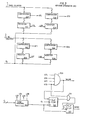
- Figure 3 is a detailed schematic representation of the window generator 240 of Figure 2, which will only allow events that occur within the bounds of window or gate 550 (of Figure 5) to be recorded in memories 20 8 and 209.
- the values of the window's left, right, top and bottom boundaries are precomputed by digital processor 35 and stored with the aid of a load control 312 in four registers 301, 302, 303 and 304.
- the outputs of registers 301-304 are fed to the first inputs of four comparators 305 through 308, respectively.
- the value of pixel counter 207 is fed to the other inputs of comparators 305 and 306 and the value of line counter 206 is fed to the other inputs of comparators 307 and 3 08 .
- comparators 305 through 3 08 When the values of line and pixel counters 206 and 207 are within the preset window bounds, appropriate comparisons are made by comparators 305 through 3 08 . These comparisons are provided at the comparator outputs G TL , GTR, GTT, and GTB, i.e. greater than left, greater than right, etc. These output signals GTL, GTR, GT T , and GT B are logically combined by a logic gate 309 to produce the logic signal WNDW, that is used to enable memories 208 and 209 and video pulse counter 210.
- a circuit comprised of a pair of flip-flops 310 and 313 and a gate 311, interrupts the digital processor immediately after the window's lower boundary is exceeded.
- Load control 312 generates pulses to reload registers 301 through 304 as DATA signals representing new window boundaries are received from digital processor 35. Load control 312 also resets interrupt logic circuits 310 and 313.
- the digital processor has computed the components of the window that surrounds this predicted point and sent them to window generator 240.
- the raster scan begins at the top of the CTVS 's field-of-view.
- the counters begin counting and, as their values do not coincide with the range of values within the window, window generator 240 prevents (locks out) the recording of any signals representing objects by disabling the CS inputs of memories 208 and 209 .
- window generator 240 unlocks memories 208 and 2 0 9 by enabling the CS inputs. This allows the recording of the objects' positions by these memories, as described earlier. As the raster scan progresses down the image, the values of the counters will no longer coincide with the allowed range of values within window generator 2 40 , and window generator 240 will lock the memories by removing the enabling signal to memories 208 and 209. When the scan exceeds the lower window boundary, window generator 240 will also generate an interrupt (INTR P ) signal which is sent to digital processor 35 to allow it to take the data from memories 208 and 209. The data is read from these memories using standard "read" techniques of conventional computers by accessing the memory's addresses and data through CPU bus interface 213.
- ITR P interrupt
- the window is used to eliminate extraneous data that will not represent objects of interest and cause unnecessary computer processing. It also is used to prevent saturation of memories 208 and 209, as are the saturation lock comprising logic gates 211 and 212 and video pulse counter 210.
- Software in digital processor 35 is used to calculate a relative error between the computed bullet positions and the measured bullet positions, and the gu n boresight position is corrected using this error. This error calculation is discussed below in detail in connection with Figures 13 and 14.
- the corrected boresight position is stored in non-volatile memory 39 for use in weapon delivery calculations.
- the initial boresight symbol position on the combining optics of the HUD is determined relative to CTVS 10 to account for camera and HUD alignment. This is done using the relative error software in the processor which positions window 550 over the expected position of the boresight symbol.
- Video processing section 36 then detects the gun cross pixel positions in the video signal and stores them in the buffer comprising memories 208 and 209. These data are then used to compute the present boresight symbol position on combining optics 22 relative to CTVS 10.
- the pilot has activated the ABC system, made a right turn and fired a short burst of tracer rounds.
- the pilot trigger pull is detected by digital processor'35 and an analytical bullet position calculation is begun using a bullet trajectory algorithm.
- window 550 For every camera field or raster scan of CTVS 10, window 550 is positioned at the predicted bullet position, as seen in frames 5c through 5f, and video processing section 36 detects the actual bullet positions relative to CTVS 10 and combining optics 22 and stores them in the buffer.
- digital processor 35 uses these data to calculate the centroid of the bullet positions and compares this centroid with the theoretical bullet position normal to the direction of the bullet stream. This difference or relative error is averaged over each camera field and a corrected boresight symbol position is calculated for the entire burst. This calculation, however, will only correct boresight errors normal to the bullet trajectory. To get a two-axis correction, a turn in the opposite direction is required as shown in Figure 9. This will yield a unique solution for the correction.
- the data representing boresight cross 540 and bullets 544 are used by the relative error processing software in digital processor 35 to determine the relative error between the actual bullet trajectory and predicted trajectory as shown in Figure 6.
- cross 640 is the reference point for the predicted bullet path
- the correction to its position is computed using relative error processing software and is stored in non-volatile memory 39.
- this automatic boresight correction routine is disengaged, the loop is opened by bypassing the relative error calculations, and the corrected position of the cross 640 remains within non-volatile memory 39 to be used for all further gunnery computations.
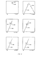
- FIG. 4 a sequence of frames is shown that depicts the bullets positions as seen in the gunnery system's optical sight at various times throughout the bullets' flight for a given turn-rate of the aircraft from which the bullets were fired.
- Frames 4a and 5a depict the viewed or sensed position of boresight symbol 440 that represents the armament datum line of the aircraft. It is from this point that predicted bullet trajectory computations are made in digital processor 35, as depicted by the predicted bullet pitch lines 442 and 542 of frames 4b - 4f and 5b - 5f, respectively.
- Figures 4 and 5 are essentially the same except that Figure 4 depicts the images when there is negligible error, while Figure 5 depicts the images when appreciable error exists.
- Figure 5 also shows the position and shape of electronic window 550 at the time the gun trigger is activated (5a) and at succeeding times (or video frames 5c - 5f).
- Figure 6 depicts a given frame of Figure 5, showing an increased relative error.
- the preset position of boresight symbol 640 is depicted, as presently stored within digital processor 35, together with the true position 640' of the armament datum line at which the boresight symbol should be.
- a dashed line 660 represents the actual trajectory of the bullet's centroid when it is far enough ahead of the aircraft to eliminate parallax.
- Bullet trajectory line 660 when extended, will cross through the correct position 640' at which the boresight symbol should be.
- the relative error 662 may be hidden from the pilot and CTVS 10. This can occur, as depicted in Figure 7, where position 740' of the correct boresight symbol lies in-line with the predicted bullet line trajectory 742. When this occurs, the bullet's centroid follows the predicted trajectory line 742 and there is no apparent error. In this case, the predicted and actual bullet trajectory lines 742 and 760, respectively, coincide.
- Figure 8 shows an iterative method by which the pilot flies a right turn, followed by a left turn, then a right turn, and so on. On each turn, a burst of rounds is fired and relative error is computed. On the first turn, the predicted 842 and actual 860 bullet trajectory lines coincide. There is no detected error and no correction is made. (This is the beginning to exemplify the hidden case depicted in Figure 7). On the second turn, the relative error between the actual bullet trajectory line 860' and predicted bullet trajectory line 842' is clearly shown.
- a first correction is made by moving the boresight symbol perpendicular to the actual bullet trajectory line 860' by the computed relative error value 862' to a new position 840'.
- the relative error is clearly shown between the actual 842 and the predicted 860'' bullet trajectory lines and a second correction is made by moving the boresight symbol perpendicular to the actual bullet trajectory line 842 by the relative error value 862'' to a newer position 840''. This process iterates until the error is of negligible value. In actual practice, only two turns are required.
- Figure 9 shows a non-iterative method by which the aircraft is flown in a first turn, the relative error is computed, and the boresight symbol's position is corrected by moving its position perpendicular to the actual bullet trajectory line as described for Figure 8. ' This is followed by a second turn that is perpendicular to the first turn and then correcting the boresight symbol position in the same manner as just described. This results in a non-iterative solution whereby boresighting results from completion of the correction for the second turn.
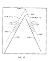
- FIG. 10 A second, non-iterative method is shown in Figure 10 whereby the aircraft is flown in a first turn, the bullets are fired, and the actual bullet trajectory line is determined and stored. The aircraft is then flown in a second turn that differs from the first turn, the bullets are fired, and again the-actual bullet trajectory line determined.
- the two actual bullet trajectory lines defined by equations
- FIG 10 Also shown in Figure 10 is averaging that can occur by solving for the centroid of the bullets at a number of points along the actual trajectory of the bullets, noted by i, i + 1, i + 2 ... and j, j + 1, j + 2.... These solutions 3 re possible for a number of video frames as depicted in Figures 4 and 5. The larger number of samples will allow the relative error processing software to obtain a more nearly accurate solution of the bullets' actual trajectory lines 1060, 1060'.
- FIG. 11 and 12 Another non-iterative method of solution that may be programmed in the preferred embodiment of the invention is shown in Figures 11 and 12, whereby the aircraft need be flown in any selected constant maneuver during the error-correction process.
- This method predicts the time and position of the bullets' centroid based upon the aircraft maneuver and compares it to the time and the bullets' centroid position measured and computed by this system. For each such time, e.g. for time t l , the actual bullet position 1171 and the predicted bullet position 1181 are compared and the relative error 1191 in the form of a vector is determined.
- the relative error vectors 1191, 1192, 1193, etc. may be averaged and the resultant error vector 1190 may be used to correct the boresight position 1140. Averaging is not necessary by this method, but is available and will yield a better solution.
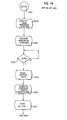
- FIGS 13 and 14 jointly constitute a functional flow diagram for the relative error processing software used by CPU 34 to calculate the corrected boresight position.
- the sighting system is placed into the automatic boresight correction (ABC) routine when the pilot selects the ABC mode with mode selector switch 42.
- ABS automatic boresight correction
- digital processor 35 branches to the ABC software routine stored in program memory 38. The major sequence of events is shown on the flow diagram of Figure 13.
- the system Upon entry at block 1301, the system is initialized for ABC, as illustrated by block 1302. This is shown in more detail by the portion of the flow diagram of Figure 14.
- the previously computed boresight position is read from non-volatile memory (NVM), as shown in block 1402, and is used to compute and position the window on the expected position of the boresight cross, as illustrated by block 1403.
- NVM non-volatile memory
- digital processor 35 waits for the CTVS raster to scan through the window and issue an interrupt (INTRP) as shown by block 1404.
- INTRP interrupt
- the data is read from memories 208 and 209 of video processing section 36, as indicated by block 1405.
- the center of the newly measured boresight position is then computed, as shown by block 1406, and stored in scratch pad memory 33 for further use.
- a maneuver counter (MCTR) is cleared to zero as shown by block 1407.
- the frame (raster) counter is cleared to zero as shown by block 1304 and the system waits for the firing of the bullets (trigger squeeze) by the pilot .
- the burst of bullets is fired, the estimated instantaneous bullet positions relative to the aircraft are computed for the maneuver the aircraft is then executing, as illustrated by block 130 6.
- the position of the window is computed according to the expected position of the bullets for the first video frame, as shown by block 1307, and the computed boundaries are loaded into window generator 240 of video processing section 36.
- the digital processor With the window positioned on the expected positions of the bullets, the digital processor now waits for the CTVS raster to scan through the window and issue an interrupt (INTRP), as indicated by block 1308.
- INTRP interrupt
- the data stored in memories 208 and 209 comprising the video processing section buffer, are read by the digital processor, as shown by block 1309.
- the centroid of the bullets is computed for this raster frame, as shown by block 1310, and the relative error is computed for this frame and stored in scratch pad memory 33, as indicated by block 1311.
- the digital processor now has the data to process the relative error for this part of the aircraft maneuver.
- the bullets will still be visible for a number of succeeding frames and holding the aircraft in the maneuver for a short period of time is easy to accomplish. Therefore, the data may be refined and an average taken over an number of video frames by allowing the software to iterate correspondingly.
- a test is performed in block 1312 to determine if the system has iterated over a predetermined number of video frames. If not, the system is caused to iterate through the next video frame. Before doing so the frame counter is incremented, as shown by block 1313.
- the system iterates through a predetermined number of video frames, storing the data each time.
- the frame counter equals the maximum count in 1312
- the system detects that the first maneuver has been completed, as indicated by block 1314.
- the stored data is retrieved and averaged for all the frames of the first maneuver and is stored temporarily, as shown by block 1315.
- the maneuver counter is incremented as shown by block 1316
- the video frame counter is zeroed as shown by block 1304, and the system waits for the pilot to execute the second maneuver, indicated by block 1303, and squeeze the trigger, as indicated by block 13 05 .
- a second maneuver is executed and the sequence as described for the first maneuver is repeated while data for each video frame is collected.
- the digital processor leaves the loop and tests for the first maneuver, as shown by block 1314.
- the result is NO, signifying that the second maneuver is in progress.
- the frame data is retrieved from store and averaged for all the frames of the second maneuver, as illustrated by block 1318.
- the data previously stored for the first maneuver is extracted from the store, as shown by block 1319, and is used with the data just collected for the second maneuver to compute the updated (corrected) position of the boresight symbol indicated by block 1320.
- the result is stored in non-volatile memory 39 for further use in computing weapon delivery solutions. This completes the ABC routine and the digital processor exits back to a system executive.
Landscapes
- Engineering & Computer Science (AREA)
- General Engineering & Computer Science (AREA)
- Aviation & Aerospace Engineering (AREA)
- Aiming, Guidance, Guns With A Light Source, Armor, Camouflage, And Targets (AREA)
- Radar Systems Or Details Thereof (AREA)
Applications Claiming Priority (2)
| Application Number | Priority Date | Filing Date | Title |
|---|---|---|---|
| US06/798,535 US4698489A (en) | 1982-09-30 | 1985-11-15 | Aircraft automatic boresight correction |
| US798535 | 1985-11-15 |
Publications (2)
| Publication Number | Publication Date |
|---|---|
| EP0226026A2 true EP0226026A2 (de) | 1987-06-24 |
| EP0226026A3 EP0226026A3 (de) | 1990-04-04 |
Family
ID=25173649
Family Applications (1)
| Application Number | Title | Priority Date | Filing Date |
|---|---|---|---|
| EP86115391A Ceased EP0226026A3 (de) | 1985-11-15 | 1986-11-06 | Automatische Justiereinrichtungskorrektur in Flugzeugen |
Country Status (6)
| Country | Link |
|---|---|
| US (1) | US4698489A (de) |
| EP (1) | EP0226026A3 (de) |
| JP (1) | JPS62155498A (de) |
| KR (1) | KR940010379B1 (de) |
| AU (1) | AU6537486A (de) |
| IL (1) | IL80483A0 (de) |
Cited By (34)
| Publication number | Priority date | Publication date | Assignee | Title |
|---|---|---|---|---|
| WO1998014747A1 (en) * | 1996-10-03 | 1998-04-09 | Barr & Stroud Limited | Target aiming system |
| RU2129696C1 (ru) * | 1998-06-22 | 1999-04-27 | Акционерное общество открытого типа "ОКБ Сухого" | Прицельная система |
| GB2375385A (en) * | 2001-03-09 | 2002-11-13 | Sagem | Weapon fire control system |
| RU2206043C1 (ru) * | 2001-12-04 | 2003-06-10 | Открытое акционерное общество "ОКБ Сухого" | Способ и система управления вооружением летательного аппарата |
| RU2311659C2 (ru) * | 2005-06-14 | 2007-11-27 | Санкт-Петербургское высшее училище радиоэлектроники ПВО | Радиолокационная система целеуказания |
| US8684918B2 (en) | 2009-10-02 | 2014-04-01 | Covidien Lp | Single port device including selectively closeable openings |
| USD712033S1 (en) | 2007-10-05 | 2014-08-26 | Covidien Lp | Seal anchor for use in surgical procedures |
| USD738500S1 (en) | 2008-10-02 | 2015-09-08 | Covidien Lp | Seal anchor for use in surgical procedures |
| US9707011B2 (en) | 2014-11-12 | 2017-07-18 | Covidien Lp | Attachments for use with a surgical access device |
| US10064649B2 (en) | 2014-07-07 | 2018-09-04 | Covidien Lp | Pleated seal for surgical hand or instrument access |
| US10675056B2 (en) | 2017-09-07 | 2020-06-09 | Covidien Lp | Access apparatus with integrated fluid connector and control valve |
| US10792071B2 (en) | 2019-02-11 | 2020-10-06 | Covidien Lp | Seals for surgical access assemblies |
| US10828065B2 (en) | 2017-08-28 | 2020-11-10 | Covidien Lp | Surgical access system |
| US11000313B2 (en) | 2019-04-25 | 2021-05-11 | Covidien Lp | Seals for surgical access devices |
| US11160682B2 (en) | 2017-06-19 | 2021-11-02 | Covidien Lp | Method and apparatus for accessing matter disposed within an internal body vessel |
| US11166748B2 (en) | 2019-02-11 | 2021-11-09 | Covidien Lp | Seal assemblies for surgical access assemblies |
| US11259841B2 (en) | 2019-06-21 | 2022-03-01 | Covidien Lp | Seal assemblies for surgical access assemblies |
| US11259840B2 (en) | 2019-06-21 | 2022-03-01 | Covidien Lp | Valve assemblies for surgical access assemblies |
| US11357542B2 (en) | 2019-06-21 | 2022-06-14 | Covidien Lp | Valve assembly and retainer for surgical access assembly |
| US11389193B2 (en) | 2018-10-02 | 2022-07-19 | Covidien Lp | Surgical access device with fascial closure system |
| US11399865B2 (en) | 2019-08-02 | 2022-08-02 | Covidien Lp | Seal assemblies for surgical access assemblies |
| US11413065B2 (en) | 2019-06-28 | 2022-08-16 | Covidien Lp | Seal assemblies for surgical access assemblies |
| US11413068B2 (en) | 2019-05-09 | 2022-08-16 | Covidien Lp | Seal assemblies for surgical access assemblies |
| US11432843B2 (en) | 2019-09-09 | 2022-09-06 | Covidien Lp | Centering mechanisms for a surgical access assembly |
| US11446058B2 (en) | 2020-03-27 | 2022-09-20 | Covidien Lp | Fixture device for folding a seal member |
| US11457949B2 (en) | 2018-10-12 | 2022-10-04 | Covidien Lp | Surgical access device and seal guard for use therewith |
| US11464540B2 (en) | 2020-01-17 | 2022-10-11 | Covidien Lp | Surgical access device with fixation mechanism |
| US11523842B2 (en) | 2019-09-09 | 2022-12-13 | Covidien Lp | Reusable surgical port with disposable seal assembly |
| US11576701B2 (en) | 2020-03-05 | 2023-02-14 | Covidien Lp | Surgical access assembly having a pump |
| US11622790B2 (en) | 2020-05-21 | 2023-04-11 | Covidien Lp | Obturators for surgical access assemblies and methods of assembly thereof |
| US11717321B2 (en) | 2020-04-24 | 2023-08-08 | Covidien Lp | Access assembly with retention mechanism |
| US11751908B2 (en) | 2020-06-19 | 2023-09-12 | Covidien Lp | Seal assembly for surgical access assemblies |
| US11812991B2 (en) | 2019-10-18 | 2023-11-14 | Covidien Lp | Seal assemblies for surgical access assemblies |
| US12324606B2 (en) | 2020-01-28 | 2025-06-10 | Covidien Lp | Seal assemblies for surgical access assemblies |
Families Citing this family (27)
| Publication number | Priority date | Publication date | Assignee | Title |
|---|---|---|---|---|
| JPS6483424A (en) * | 1987-09-25 | 1989-03-29 | Honda Motor Co Ltd | Indicator for vehicle |
| JPS6450133U (de) * | 1987-09-25 | 1989-03-28 | ||
| US5454265A (en) * | 1991-06-20 | 1995-10-03 | Diehl Gmbh & Co. | Installation for the measurement of the altitude of a surface wind, particularly for improving the hitting accuracy of unguided projectiles |
| US5577733A (en) * | 1994-04-08 | 1996-11-26 | Downing; Dennis L. | Targeting system |
| DE19716199A1 (de) * | 1997-04-18 | 1998-10-22 | Rheinmetall Ind Ag | Verfahren zum Richten der Waffe einer Waffenanlage und Waffenanlage zur Durchführung des Verfahrens |
| DE19716198C2 (de) * | 1997-04-18 | 1999-11-04 | Rheinmetall W & M Gmbh | Waffenanlage |
| DE10131720B4 (de) * | 2001-06-30 | 2017-02-23 | Robert Bosch Gmbh | Head-Up Display System und Verfahren |
| DK1329683T3 (da) * | 2002-01-16 | 2005-12-12 | Contraves Ag | Fremgangsmåde og apparat til kompensering af skydefejl og system-computer til våbensystem |
| US7292262B2 (en) * | 2003-07-21 | 2007-11-06 | Raytheon Company | Electronic firearm sight, and method of operating same |
| US7121183B2 (en) * | 2004-03-29 | 2006-10-17 | Honeywell International Inc. | Methods and systems for estimating weapon effectiveness |
| US8074555B1 (en) * | 2008-09-24 | 2011-12-13 | Kevin Michael Sullivan | Methodology for bore sight alignment and correcting ballistic aiming points using an optical (strobe) tracer |
| US8172139B1 (en) | 2010-11-22 | 2012-05-08 | Bitterroot Advance Ballistics Research, LLC | Ballistic ranging methods and systems for inclined shooting |
| JP6041547B2 (ja) * | 2012-06-08 | 2016-12-07 | 三菱電機株式会社 | 追尾装置 |
| WO2014186049A2 (en) * | 2013-03-21 | 2014-11-20 | Kms Consulting, Llc | Apparatus for correcting ballistic errors using laser induced fluorescent (strobe) tracers |
| DE102013208735A1 (de) * | 2013-05-13 | 2014-11-13 | Robert Bosch Gmbh | Verfahren und Vorrichtung zum Ermitteln und Kompensieren eines Dejustagewinkels eines Radarsensors eines Fahrzeugs |
| US20150287224A1 (en) * | 2013-10-01 | 2015-10-08 | Technology Service Corporation | Virtual tracer methods and systems |
| US10113837B2 (en) | 2015-11-03 | 2018-10-30 | N2 Imaging Systems, LLC | Non-contact optical connections for firearm accessories |
| US10753709B2 (en) | 2018-05-17 | 2020-08-25 | Sensors Unlimited, Inc. | Tactical rails, tactical rail systems, and firearm assemblies having tactical rails |
| US10645348B2 (en) | 2018-07-07 | 2020-05-05 | Sensors Unlimited, Inc. | Data communication between image sensors and image displays |
| US11079202B2 (en) | 2018-07-07 | 2021-08-03 | Sensors Unlimited, Inc. | Boresighting peripherals to digital weapon sights |
| US10742913B2 (en) | 2018-08-08 | 2020-08-11 | N2 Imaging Systems, LLC | Shutterless calibration |
| US10921578B2 (en) | 2018-09-07 | 2021-02-16 | Sensors Unlimited, Inc. | Eyecups for optics |
| US11122698B2 (en) | 2018-11-06 | 2021-09-14 | N2 Imaging Systems, LLC | Low stress electronic board retainers and assemblies |
| US10801813B2 (en) | 2018-11-07 | 2020-10-13 | N2 Imaging Systems, LLC | Adjustable-power data rail on a digital weapon sight |
| US10796860B2 (en) | 2018-12-12 | 2020-10-06 | N2 Imaging Systems, LLC | Hermetically sealed over-molded button assembly |
| US11143838B2 (en) | 2019-01-08 | 2021-10-12 | N2 Imaging Systems, LLC | Optical element retainers |
| US20210180917A1 (en) * | 2019-12-11 | 2021-06-17 | Plano Molding Company, Llc | System and method for monitoring and assessing projectile performance |
Family Cites Families (15)
| Publication number | Priority date | Publication date | Assignee | Title |
|---|---|---|---|---|
| US3136992A (en) * | 1958-06-30 | 1964-06-09 | Gen Electric | Fire control system harmonization |
| US3716696A (en) * | 1970-09-04 | 1973-02-13 | Honeywell Inc | Projectile stream display apparatus |
| US4015258A (en) * | 1971-04-07 | 1977-03-29 | Northrop Corporation | Weapon aiming system |
| US3798795A (en) * | 1972-07-03 | 1974-03-26 | Rmc Res Corp | Weapon aim evaluation system |
| US4202246A (en) * | 1973-10-05 | 1980-05-13 | General Dynamics Pomona Division | Multiple co-axial optical sight and closed loop gun control system |
| US4104730A (en) * | 1976-04-02 | 1978-08-01 | Westinghouse Electric Corp. | Boresight adjustment for a harmonic oscillator coordinate converter |
| US4020739A (en) * | 1976-07-16 | 1977-05-03 | The United States Of America As Represented By The Secretary Of The Army | Fire control system |
| GB1563094A (en) * | 1976-09-08 | 1980-03-19 | Emi Ltd | Apparatus for monitoring the aim of a launcher of projectiles |
| US4099719A (en) * | 1977-04-28 | 1978-07-11 | Atari Inc. | System and method for automatic alignment of gun with video display |
| GB2030686B (en) * | 1978-09-13 | 1983-03-02 | Solartron Electronic Group | Weapon training systems |
| GB2030272B (en) * | 1978-09-13 | 1982-11-03 | Solartron Electronic Group | Alignment of weapon training systems |
| US4312262A (en) * | 1979-02-22 | 1982-01-26 | General Electric Company | Relative velocity gunsight system and method |
| NL7905061A (nl) * | 1979-06-29 | 1980-12-31 | Hollandse Signaalapparaten Bv | Werkwijze en inrichting voor het automatisch meten van richtfouten en het verbeteren van richtwaarden bij het schieten en richten van ballistische wapens tegen bewegende doelen. |
| US4308015A (en) * | 1979-12-20 | 1981-12-29 | General Electric Company | System and method for aircraft gunnery training and accuracy evaluation |
| EP0105432B1 (de) * | 1982-09-30 | 1990-01-24 | General Electric Company | Automatische Schussverbesserung für Flugzeuge |
-
1985
- 1985-11-15 US US06/798,535 patent/US4698489A/en not_active Expired - Fee Related
-
1986
- 1986-11-04 IL IL80484A patent/IL80483A0/xx not_active IP Right Cessation
- 1986-11-06 EP EP86115391A patent/EP0226026A3/de not_active Ceased
- 1986-11-14 KR KR1019860009614A patent/KR940010379B1/ko not_active Expired - Fee Related
- 1986-11-14 JP JP61270034A patent/JPS62155498A/ja active Pending
- 1986-11-17 AU AU65374/86A patent/AU6537486A/en not_active Abandoned
Cited By (56)
| Publication number | Priority date | Publication date | Assignee | Title |
|---|---|---|---|---|
| US6260466B1 (en) | 1996-10-03 | 2001-07-17 | Barr & Stroud Limited | Target aiming system |
| WO1998014747A1 (en) * | 1996-10-03 | 1998-04-09 | Barr & Stroud Limited | Target aiming system |
| RU2129696C1 (ru) * | 1998-06-22 | 1999-04-27 | Акционерное общество открытого типа "ОКБ Сухого" | Прицельная система |
| GB2375385A (en) * | 2001-03-09 | 2002-11-13 | Sagem | Weapon fire control system |
| GB2375385B (en) * | 2001-03-09 | 2004-08-25 | Sagem | Weapon fire control system |
| DE10208102B4 (de) * | 2001-03-09 | 2012-01-12 | Sagem Sa | Schießleitvorrichtung |
| RU2206043C1 (ru) * | 2001-12-04 | 2003-06-10 | Открытое акционерное общество "ОКБ Сухого" | Способ и система управления вооружением летательного аппарата |
| RU2311659C2 (ru) * | 2005-06-14 | 2007-11-27 | Санкт-Петербургское высшее училище радиоэлектроники ПВО | Радиолокационная система целеуказания |
| USD736921S1 (en) | 2007-10-05 | 2015-08-18 | Covidien Lp | Seal anchor for use in surgical procedures |
| USD712033S1 (en) | 2007-10-05 | 2014-08-26 | Covidien Lp | Seal anchor for use in surgical procedures |
| USD712034S1 (en) | 2007-10-05 | 2014-08-26 | Covidien Lp | Seal anchor for use in surgical procedures |
| USD738500S1 (en) | 2008-10-02 | 2015-09-08 | Covidien Lp | Seal anchor for use in surgical procedures |
| US9179934B2 (en) | 2009-10-02 | 2015-11-10 | Covidien Lp | Single port device including selectively closeable openings |
| US8684918B2 (en) | 2009-10-02 | 2014-04-01 | Covidien Lp | Single port device including selectively closeable openings |
| US8894575B2 (en) | 2009-10-02 | 2014-11-25 | Covidien Lp | Single port device including selectively closeable openings |
| US8795164B2 (en) | 2009-10-02 | 2014-08-05 | Covidien Lp | Single port device including selectively closeable openings |
| US8986203B2 (en) | 2009-10-02 | 2015-03-24 | Covidien Lp | Single port device including selectively closeable openings |
| US10064649B2 (en) | 2014-07-07 | 2018-09-04 | Covidien Lp | Pleated seal for surgical hand or instrument access |
| US11191567B2 (en) | 2014-11-12 | 2021-12-07 | Covidien Lp | Attachments for use with a surgical access device |
| US9707011B2 (en) | 2014-11-12 | 2017-07-18 | Covidien Lp | Attachments for use with a surgical access device |
| US10420587B2 (en) | 2014-11-12 | 2019-09-24 | Covidien Lp | Attachments for use with a surgical access device |
| US11160682B2 (en) | 2017-06-19 | 2021-11-02 | Covidien Lp | Method and apparatus for accessing matter disposed within an internal body vessel |
| US10828065B2 (en) | 2017-08-28 | 2020-11-10 | Covidien Lp | Surgical access system |
| US11666359B2 (en) | 2017-09-07 | 2023-06-06 | Covidien Lp | Access apparatus with integrated fluid connector and control valve |
| US10675056B2 (en) | 2017-09-07 | 2020-06-09 | Covidien Lp | Access apparatus with integrated fluid connector and control valve |
| US11389193B2 (en) | 2018-10-02 | 2022-07-19 | Covidien Lp | Surgical access device with fascial closure system |
| US11925387B2 (en) | 2018-10-02 | 2024-03-12 | Covidien Lp | Surgical access device with fascial closure system |
| US11457949B2 (en) | 2018-10-12 | 2022-10-04 | Covidien Lp | Surgical access device and seal guard for use therewith |
| US12029449B2 (en) | 2019-02-11 | 2024-07-09 | Covidien Lp | Seals for surgical access assemblies |
| US11751910B2 (en) | 2019-02-11 | 2023-09-12 | Covidien Lp | Seal assemblies for surgical access assemblies |
| US11166748B2 (en) | 2019-02-11 | 2021-11-09 | Covidien Lp | Seal assemblies for surgical access assemblies |
| US10792071B2 (en) | 2019-02-11 | 2020-10-06 | Covidien Lp | Seals for surgical access assemblies |
| US11471191B2 (en) | 2019-02-11 | 2022-10-18 | Covidien LLP | Seals for surgical access assemblies |
| US11717323B2 (en) | 2019-04-25 | 2023-08-08 | Covidien Lp | Seals for surgical access devices |
| US11000313B2 (en) | 2019-04-25 | 2021-05-11 | Covidien Lp | Seals for surgical access devices |
| US11413068B2 (en) | 2019-05-09 | 2022-08-16 | Covidien Lp | Seal assemblies for surgical access assemblies |
| US12127762B2 (en) | 2019-06-21 | 2024-10-29 | Covidien, LP | Valve assembly and retainer for surgical access assembly |
| US11259841B2 (en) | 2019-06-21 | 2022-03-01 | Covidien Lp | Seal assemblies for surgical access assemblies |
| US11259840B2 (en) | 2019-06-21 | 2022-03-01 | Covidien Lp | Valve assemblies for surgical access assemblies |
| US11357542B2 (en) | 2019-06-21 | 2022-06-14 | Covidien Lp | Valve assembly and retainer for surgical access assembly |
| US11413065B2 (en) | 2019-06-28 | 2022-08-16 | Covidien Lp | Seal assemblies for surgical access assemblies |
| US11399865B2 (en) | 2019-08-02 | 2022-08-02 | Covidien Lp | Seal assemblies for surgical access assemblies |
| US11523842B2 (en) | 2019-09-09 | 2022-12-13 | Covidien Lp | Reusable surgical port with disposable seal assembly |
| US12310620B2 (en) | 2019-09-09 | 2025-05-27 | Covidien Lp | Reusable surgical port with disposable seal assembly |
| US12035940B2 (en) | 2019-09-09 | 2024-07-16 | Covidien Lp | Centering mechanisms for a surgical access assembly |
| US11432843B2 (en) | 2019-09-09 | 2022-09-06 | Covidien Lp | Centering mechanisms for a surgical access assembly |
| US11812991B2 (en) | 2019-10-18 | 2023-11-14 | Covidien Lp | Seal assemblies for surgical access assemblies |
| US11464540B2 (en) | 2020-01-17 | 2022-10-11 | Covidien Lp | Surgical access device with fixation mechanism |
| US11839405B2 (en) | 2020-01-17 | 2023-12-12 | Covidien Lp | Surgical access device with fixation mechanism |
| US12324606B2 (en) | 2020-01-28 | 2025-06-10 | Covidien Lp | Seal assemblies for surgical access assemblies |
| US11576701B2 (en) | 2020-03-05 | 2023-02-14 | Covidien Lp | Surgical access assembly having a pump |
| US12064141B2 (en) | 2020-03-27 | 2024-08-20 | Covidien Lp | Fixture device for folding a seal member |
| US11446058B2 (en) | 2020-03-27 | 2022-09-20 | Covidien Lp | Fixture device for folding a seal member |
| US11717321B2 (en) | 2020-04-24 | 2023-08-08 | Covidien Lp | Access assembly with retention mechanism |
| US11622790B2 (en) | 2020-05-21 | 2023-04-11 | Covidien Lp | Obturators for surgical access assemblies and methods of assembly thereof |
| US11751908B2 (en) | 2020-06-19 | 2023-09-12 | Covidien Lp | Seal assembly for surgical access assemblies |
Also Published As
| Publication number | Publication date |
|---|---|
| US4698489A (en) | 1987-10-06 |
| AU6537486A (en) | 1987-05-21 |
| IL80483A0 (en) | 1987-02-27 |
| KR940010379B1 (ko) | 1994-10-22 |
| KR870005230A (ko) | 1987-06-05 |
| JPS62155498A (ja) | 1987-07-10 |
| EP0226026A3 (de) | 1990-04-04 |
Similar Documents
| Publication | Publication Date | Title |
|---|---|---|
| US4698489A (en) | Aircraft automatic boresight correction | |
| US4312262A (en) | Relative velocity gunsight system and method | |
| US4442491A (en) | Training evaluation process | |
| EP0929787B1 (de) | Zielanvisierungssystem | |
| US5077609A (en) | Optoelectronic system of assistance in attack and navigation missions | |
| US4015258A (en) | Weapon aiming system | |
| US6125308A (en) | Method of passive determination of projectile miss distance | |
| JPH0124275B2 (de) | ||
| KR102079688B1 (ko) | 대공화기 및 그의 서브 전자광학추적장치를 이용한 사격통제방법 | |
| CN104089529A (zh) | 使用光纤陀螺仪对战斗机武器系统进行校准的方法及设备 | |
| EP0105432B1 (de) | Automatische Schussverbesserung für Flugzeuge | |
| EP0042004B1 (de) | Schiessimulationssystem | |
| CA2023659A1 (en) | Method and apparatus for improving the accuracy of fire | |
| JP2000356500A (ja) | 小火器用照準装置 | |
| CA1199490A (en) | Aircraft automatic boresight correction | |
| US3586770A (en) | Adaptive gated digital tracker | |
| EP2746716A1 (de) | Optische Vorrichtung mit einem Modus zur Gruppierung von Schüssen zur Verwendung mit präzisionsgeführten Feuerwaffen | |
| US3716696A (en) | Projectile stream display apparatus | |
| SE427383C (sv) | Anordning for utbildning av skyttar i riktforfarande respektive malfoljning | |
| RU2712367C2 (ru) | Способ внутреннего целеуказания с индикацией целей для образцов бронетанкового вооружения | |
| DE4111935C2 (de) | ||
| EP0347968B1 (de) | Verfahren und Vorrichtung zur Steuerung eines Waffensystems | |
| GB1605209A (en) | Weapon locating apparatus | |
| KR850000014B1 (ko) | 사격모의 시스템 | |
| Gilbert et al. | Snap-Shoot Gunsight for Fixed-Gun Fighter Aircraft |
Legal Events
| Date | Code | Title | Description |
|---|---|---|---|
| PUAI | Public reference made under article 153(3) epc to a published international application that has entered the european phase |
Free format text: ORIGINAL CODE: 0009012 |
|
| AK | Designated contracting states |
Kind code of ref document: A2 Designated state(s): CH DE FR GB IT LI NL SE |
|
| PUAL | Search report despatched |
Free format text: ORIGINAL CODE: 0009013 |
|
| AK | Designated contracting states |
Kind code of ref document: A3 Designated state(s): CH DE FR GB IT LI NL SE |
|
| 17P | Request for examination filed |
Effective date: 19900906 |
|
| 17Q | First examination report despatched |
Effective date: 19920702 |
|
| STAA | Information on the status of an ep patent application or granted ep patent |
Free format text: STATUS: THE APPLICATION HAS BEEN REFUSED |
|
| 18R | Application refused |
Effective date: 19940616 |
|
| RIN1 | Information on inventor provided before grant (corrected) |
Inventor name: TYE, GENE Inventor name: HICKIN, CHARLES WYNDHAM ROBINSON |