EP0226059A2 - Ensemble de collimation déconnectable - Google Patents
Ensemble de collimation déconnectable Download PDFInfo
- Publication number
- EP0226059A2 EP0226059A2 EP86116034A EP86116034A EP0226059A2 EP 0226059 A2 EP0226059 A2 EP 0226059A2 EP 86116034 A EP86116034 A EP 86116034A EP 86116034 A EP86116034 A EP 86116034A EP 0226059 A2 EP0226059 A2 EP 0226059A2
- Authority
- EP
- European Patent Office
- Prior art keywords
- sleeve
- collimation
- optical
- assembly according
- collimation assembly
- Prior art date
- Legal status (The legal status is an assumption and is not a legal conclusion. Google has not performed a legal analysis and makes no representation as to the accuracy of the status listed.)
- Granted
Links
Images

Classifications
-
- G—PHYSICS
- G02—OPTICS
- G02B—OPTICAL ELEMENTS, SYSTEMS OR APPARATUS
- G02B7/00—Mountings, adjusting means, or light-tight connections, for optical elements
- G02B7/02—Mountings, adjusting means, or light-tight connections, for optical elements for lenses
-
- G—PHYSICS
- G02—OPTICS
- G02B—OPTICAL ELEMENTS, SYSTEMS OR APPARATUS
- G02B6/00—Light guides; Structural details of arrangements comprising light guides and other optical elements, e.g. couplings
- G02B6/24—Coupling light guides
- G02B6/26—Optical coupling means
- G02B6/32—Optical coupling means having lens focusing means positioned between opposed fibre ends
-
- G—PHYSICS
- G02—OPTICS
- G02B—OPTICAL ELEMENTS, SYSTEMS OR APPARATUS
- G02B6/00—Light guides; Structural details of arrangements comprising light guides and other optical elements, e.g. couplings
- G02B6/24—Coupling light guides
- G02B6/36—Mechanical coupling means
- G02B6/38—Mechanical coupling means having fibre to fibre mating means
- G02B6/3801—Permanent connections, i.e. wherein fibres are kept aligned by mechanical means
- G02B6/3803—Adjustment or alignment devices for alignment prior to splicing
Definitions
- This invention relates to a disconnectahle collimation assembly which makes it possible to ensure access to any optical component requiring a separation between fibers without producing excessive attenuation.
- the invention proposes a disconnectahle collimation assemhly (or disconnectable optical point) which can he separate from any equipment and which embodies the collimation function by itself. It can he designed so as to receive standard optical tips and optical fibers with diameters ranging from 50/125 ⁇ to 100/140 ⁇ .
- This collimation assembly is based on the principle of the predetermined positioning of an optical axis relative to a reference surface.
- each optical axis of an optical point (the fiher-collimation assemhly means) must he strictly perpendicular to its contact surface and the fiber-lens interface must he optimized.
- the positioning of the lens will he optimized directly within the mechanical part of the optical point, the contact face contacting the reference face of a micromanipulation tool. In so doing the influence of imprecisions of the mechanical assembly and of transfers of precision on the fiber-lens coupling are minimized.
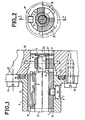
- a collimation assembly according to the invention is represented in Figures 1 and 2.
- Figure 1 is a section along axis A-A and Figure 2 along axis R-B.
- the collimation assembly includes a mechanical part and optical collimation means.
- the mechanical part assures the alignment of the connection of the optical fiber and the collimation means, the positioning and the fixation of the optical point on the equipment to he fitted therewith.
- the mechanical assembly comprises a sleeve 1 mounted in a base 2, a centering device 3 fitted in sleeve 1, a spring 4 serving to press the tip 5 of an optical plug to the hottom of its lodging, and preferably a stop washer 6.
- the assembly also comprises means of fixation of sleeve 1 in hase 2, for example a set-screw 7 screwed directly into the sleeve, and with a head received in a recess 8 in the hase.
- the centering device 3 is introduced through the front of the sleeve and fitted hy force.
- the spring is fitted in a groove 9 milled in the full thickness of the sleeve.
- the dimensions of the groove and its form assure the retention of the spring without letting it fall inside the sleeve.
- the bore in the sleeve has a section formed hy the junction of a circular part and a V-shaped part. This bore permits the reception and positioning of a plug whose tip 5 has a section of identical form. The positioning v is carefully machined.
- the sleeve has another cutaway 10 opposite two holes 11. Cutaway 10 and holes 11 permit access to the parts situated on either side of the centering device 3 when the latter is in place. They allow for passage of a lens micromanipulation tool.
- Centering device 3 permits holding the collimation means, in this case a bar lens 12, in its position of optimum adjustment by gluing. It has a tubular shape and the diameter of its bore is such that it permits orienting the lens with the use of the micromanipulation tool.
- An adhesive joint 13 integrates the lens 12 with the centering device 3.
- Rase 2 provides protection for the collimation unit, its mounting on the device 30 to he connected, for example, by the use of screws 14 and the mounting of an optical plug hy means of a thread located on its rear part. It also has internal error-prevention keys defined hy longitudinal cavities 15, 16 and 17 to facilitate the placement of the plug. Cavity 17 also serves to accommodate spring 4.
- Rase 2 in particular, has a strictly machined reference surface 18 which will come in contact with a reference surface of the device to b P connected. A slot 19 receives a gasket 20.
- washer 6 It can be advantageous to equip the collimation assembly with a washer 6 to serve as a stop for lens 12. This washer will serve to diminish the force applied to adhesive joint 13 by the spring which generally is used with an optical plug. Washer 6 has one face machined so as to follow the convex face of the lens 12. It is integrated with the optical point by a peripheral adhesive joint 21. To assure a good mounting of washer 6, a small track ?? is machined in the front part of the hore in the sleeve to serve to serve as a point of attachment for peripheral joint 21.
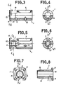
- Sleeve 1 is represented alone in Figures 3 and 4 which are respectively front and side views.
- Figure 3 is a sectional view along axis D-D and Figure 4 a sectional view along axis C-C.
- These figures permit a hetter understanding of the configuration of the sleeve.
- Threaded hole 23 permits the mounting of the sleeve in the base hy means of a set-screw.
- the v 24 for receiving the tip extends from the rear of the sleeve to a shoulder 25 of cutaway 10.
- a cutout 26 made in the wall of the sleeve extending approximately to the axis of the sleeve, which will serve for passage of a micromanipulation tool.
- Figures 5 and 6 represent sleeve 1 equipped with centering device 3 which is force-fitted to shoulder 25.
- Figure 5 is a section along axis F-F and Figure 6 along the axis E-E passing through the middle of the centering device.
- a flared hole 27 is formed, common to the sleeve and the centering device, for the injection of adhesive.
- Figures 7 and R are front and side views of base 2.
- Figure 8 is a sectional view along axis G-G. There is shown slot 19, the receptacle 8 for the screw fixing the sleeve on the base, reference face 18 and cavities 15, 16 and 17.
- the four holes 31 are for passage of the screws mounting the hase on the device to be connected.
- the thread 32 of the rear part of the base permits screwing in the optical plug to be connected.
- a peripheral slot 33 permits the installation of a toric gasket between the base and the optical plug.
- Glass lenses have the advantage of good resistance to the wear resulting from the contact of the plug tips. They can, however, he replaced hy plastic lenses. In this case it is preferable to reinforce their resistance to wear as shown in Figures 9 and 10.
- wear protection is provided by an axial cavity 35 in lens 12.
- the protection is provided by the interposition of a metal washer 36 hetween the tip and the lens.
- Length "a" represents the focal length.
- the device is assembled as follows.
- Sleeve 1, equipped with centering device 3 and spring 4 is introduced into base 2 and integrated with this base.
- Lens 12 can then be introduced followed by the operation of optimization, in which the optical axis of the collimation assembly is made strictly perpendicular to the reference face 18. This operation is carried out with an optimization bench.
- Figure 11 is a schematic view of an optimization bench for a collimation assembly according to this invention. It comprises a coherent laser 40 generating a light beam 41 toward the convex face of a bar lens 42.
- the laser can be a 10 mW laser generating a signal of 630 nm.
- Lens 42 focuses the light beam on the end of an optical fiber 43 which is 300 m in length and has a diameter of 50/125 n . This fiber length permits the extinction of the cladding modes.
- the other end of the fiber is molded very precisely inside a standard plug which will be mounted on base 2 of the future optical point.
- the base is integrated with a micromanipulation device 44 by four screws fitting in holes 31.
- the device is placed on a rigid bench 45 on which are placed, facing one another, device 44 and a screen 46 at a distance of about 1200 mm.
- the first stage in the optimization operation is the establishment of the target on the screen.
- a lens is glued with no special precautions in the centering device.
- An optical point of poor quality is obtained, which can serve to determine the point of the target to be aimed at in order to align the lenses and the standard plug as precisely as possible.
- the procedure as as follows. The optical point is rotated on itself, 90° at a time. Each time, the contour of the light spot on screen 46 is traced very precisely. Then the center of the circle which circumscribes the four circles traced previously is determined geometrically. Around this center a circle is traced, with a diameter equal to that of the light spot.
- This circle constitutes the target to he aimed at by m i croman ip ula ting the lens in front of the standard plug.
- the target circle is made to merge with the light spot, the optical axis of the collimation assembly will he considered to he perpendicular to the plane of reference of the base.
- the lens will then he glued in its centering device.
- the glue is introduced through hole 27.
- the glue is one which hardens under ultraviolet radiation directed toward hole 27 or through the front face of the lens.
- the micromanipulation of the lens is done in all possible directions.
- the standard plug has a tip without a spring and hence is nonretractahle. Holes 11 in the sleeve permit the passage of manipulation rods. Cutaway 10 and the cutout 26 permit the introduction of a smally held hy the micromanipulation arm.
- stop washer 6 After gluing the lens, stop washer 6 can he installed and glued in turn.
- All optical points embodied in this manner will be capable of heing aligned two hy two with the least possible insertion loss in the transmission of a light signal.
- the molding of fibers in diameters of 50/125 ⁇ and 100/140 ⁇ is now done with a precision of less then ⁇ 3 ⁇ of the theoretical reference dimensions, which makes for small variations from the lens-reference fiber coupling to the lens-utilisation fiher coupling.
- the invention is not limited to the type of plug described above, but can he adapted to other plugs with modification of the forms of the base or the sleeve to assure guidance of the plugs.
- This type of disconnectable optical point can he used on any optical device inserted on an optical fiber line, for example on couplers, attenuators, switches, and any type of sensors.
Landscapes
- Physics & Mathematics (AREA)
- General Physics & Mathematics (AREA)
- Optics & Photonics (AREA)
- Optical Couplings Of Light Guides (AREA)
- Mechanical Coupling Of Light Guides (AREA)
Applications Claiming Priority (2)
| Application Number | Priority Date | Filing Date | Title |
|---|---|---|---|
| FR8518427 | 1985-12-12 | ||
| FR8518427A FR2591761B1 (fr) | 1985-12-12 | 1985-12-12 | Ensemble de collimation deconnectable |
Publications (3)
| Publication Number | Publication Date |
|---|---|
| EP0226059A2 true EP0226059A2 (fr) | 1987-06-24 |
| EP0226059A3 EP0226059A3 (en) | 1987-10-21 |
| EP0226059B1 EP0226059B1 (fr) | 1991-08-28 |
Family
ID=9325720
Family Applications (1)
| Application Number | Title | Priority Date | Filing Date |
|---|---|---|---|
| EP86116034A Expired EP0226059B1 (fr) | 1985-12-12 | 1986-11-20 | Ensemble de collimation déconnectable |
Country Status (5)
| Country | Link |
|---|---|
| US (1) | US4776663A (fr) |
| EP (1) | EP0226059B1 (fr) |
| JP (1) | JPS62150306A (fr) |
| DE (1) | DE3681131D1 (fr) |
| FR (1) | FR2591761B1 (fr) |
Cited By (1)
| Publication number | Priority date | Publication date | Assignee | Title |
|---|---|---|---|---|
| EP2713190B1 (fr) * | 2012-09-27 | 2018-06-06 | Omron Corporation | Tête de fibre optique |
Families Citing this family (9)
| Publication number | Priority date | Publication date | Assignee | Title |
|---|---|---|---|---|
| US4850669A (en) * | 1986-08-15 | 1989-07-25 | Welker Engineering Company | Explosion-proof optical fiber connector for a light source |
| JPS63282709A (ja) * | 1987-05-15 | 1988-11-18 | Nec Corp | 光コネクタのプラグ |
| DK158169C (da) * | 1987-08-31 | 1990-09-03 | Dantec Elektronik Med | Indkoblingsmanipulator for laserlys til en optisk fiber |
| US4979791A (en) * | 1989-12-08 | 1990-12-25 | Amp Incorporated | Laser diode connector assembly |
| SE469762B (sv) * | 1992-02-28 | 1993-09-06 | Ingvar Nodfelt | Kopplingsanordning foer axiell sammankoppling av aendpartierna av optiska fibrer |
| US5381438A (en) * | 1993-08-26 | 1995-01-10 | Industrial Technology Research Institute | Laser diode unit including an adjusting member provided with a through hole |
| GB0111363D0 (en) * | 2001-05-09 | 2001-07-04 | Point Source Ltd | Optical component |
| US10782481B1 (en) * | 2019-03-13 | 2020-09-22 | The Boeing Company | Optical fasteners having heads with lenses |
| US11220321B2 (en) | 2019-03-13 | 2022-01-11 | The Boeing Company | Window systems including optical fasteners |
Family Cites Families (10)
| Publication number | Priority date | Publication date | Assignee | Title |
|---|---|---|---|---|
| GB1579027A (en) * | 1976-05-25 | 1980-11-12 | Combined Optical Ind Ltd | Fibre optic waveguide connectors |
| US4204743A (en) * | 1976-06-21 | 1980-05-27 | U.S. Philips Corporation | Connector for coupling optical fibers to an emitter or receiver of luminous energy |
| NL7806829A (nl) * | 1978-06-26 | 1979-12-28 | Philips Nv | Snel losneembare koppeling voor lichtgeleidende vezels. |
| JPS5814102A (ja) * | 1981-07-17 | 1983-01-26 | Toshiba Corp | 赤外線用光フアイバ− |
| US4447119A (en) * | 1981-11-02 | 1984-05-08 | Gould, Inc. | Apparatus for maintaining an optical fiber and a focusing means |
| US4575181A (en) * | 1983-04-26 | 1986-03-11 | Tokyo Shibaura Denki Kabushiki Kaisha | Optical fiber assembly with cladding light scattering means |
| DD218963A1 (de) * | 1983-05-11 | 1985-02-20 | Inst Fuer Nachrichtentechnik | Justierbare, mikrooptische koppelvorrichtung fuer lichtleiter |
| FR2547425B1 (fr) * | 1983-06-10 | 1987-04-10 | Socapex | Procede et dispositif de centrage relatif d'une fibre optique et d'une lentille dans un embout, et element de connecteur ainsi obtenu |
| DE3327575A1 (de) * | 1983-07-30 | 1985-02-14 | Krone Gmbh, 1000 Berlin | Steckverbinder fuer lichtwellenleiter |
| DD239280A1 (de) * | 1985-07-11 | 1986-09-17 | Kontaktbau & Spezmaschbau Veb | Kupplungsstueck fuer endfassungen optischer lichtleitfasern |
-
1985
- 1985-12-12 FR FR8518427A patent/FR2591761B1/fr not_active Expired
-
1986
- 1986-11-20 EP EP86116034A patent/EP0226059B1/fr not_active Expired
- 1986-11-20 DE DE8686116034T patent/DE3681131D1/de not_active Expired - Lifetime
- 1986-12-08 US US06/939,371 patent/US4776663A/en not_active Expired - Fee Related
- 1986-12-11 JP JP61293557A patent/JPS62150306A/ja active Pending
Cited By (1)
| Publication number | Priority date | Publication date | Assignee | Title |
|---|---|---|---|---|
| EP2713190B1 (fr) * | 2012-09-27 | 2018-06-06 | Omron Corporation | Tête de fibre optique |
Also Published As
| Publication number | Publication date |
|---|---|
| EP0226059A3 (en) | 1987-10-21 |
| EP0226059B1 (fr) | 1991-08-28 |
| JPS62150306A (ja) | 1987-07-04 |
| FR2591761B1 (fr) | 1989-03-31 |
| FR2591761A1 (fr) | 1987-06-19 |
| DE3681131D1 (de) | 1991-10-02 |
| US4776663A (en) | 1988-10-11 |
Similar Documents
| Publication | Publication Date | Title |
|---|---|---|
| US4060309A (en) | Adjustable connector assembly for laser effect diode, focussing lens and an optical fibre in optical fibre transmission system | |
| EP0519219B1 (fr) | Dispositif pour connecter optiquement un élément optique, par exemple une fibre optique, avec une lentille | |
| US4118105A (en) | Optical coupling | |
| CA1313074C (fr) | Connecteur a lentille pour fibres optiques | |
| CA1138236A (fr) | Accouplement detachable pour fibres optiques | |
| US4889406A (en) | Tilt adjustable optical fibre connectors | |
| US4545643A (en) | Retro-reflective alignment technique for fiber optical connectors | |
| US20070211999A1 (en) | Optical Connector | |
| US4509827A (en) | Reproducible standard for aligning fiber optic connectors which employ graded refractive index rod lenses | |
| US4461538A (en) | Active receptacle having resilient sleeve-like bushing | |
| EP0395607B1 (fr) | Dispositif du contact | |
| US4383731A (en) | Opto-electronic head incorporating a very small diameter optical fibre portion and connection device incorporating such a head | |
| EP0226059A2 (fr) | Ensemble de collimation déconnectable | |
| EP0278507B1 (fr) | Module optique à semi-conducteur | |
| EP0008504B1 (fr) | Dispositif semiconducteur optoélectronique | |
| US4468087A (en) | Device for coupling two optical fibers | |
| WO1986000718A1 (fr) | Joint rotatif optique a canaux multiples | |
| EP0125829A2 (fr) | Connecteurs optiques | |
| US5108167A (en) | Method and apparatus for obtaining a simplified electro-optical signal coupling system | |
| US6113284A (en) | Optical fiber light source assembly and manufacturing method for the same | |
| US5163114A (en) | Fiber optics mode coupling light beam into an optical cavity | |
| EP0348117B1 (fr) | Connecteurs réglables à fibre optique | |
| EP0825463B1 (fr) | Connecteur optique | |
| US4890897A (en) | Single mode connector | |
| US4696539A (en) | Fiber optic cable connector |
Legal Events
| Date | Code | Title | Description |
|---|---|---|---|
| PUAI | Public reference made under article 153(3) epc to a published international application that has entered the european phase |
Free format text: ORIGINAL CODE: 0009012 |
|
| AK | Designated contracting states |
Kind code of ref document: A2 Designated state(s): DE GB IT SE |
|
| RAP1 | Party data changed (applicant data changed or rights of an application transferred) |
Owner name: SOCAPEX S.A. |
|
| PUAL | Search report despatched |
Free format text: ORIGINAL CODE: 0009013 |
|
| AK | Designated contracting states |
Kind code of ref document: A3 Designated state(s): DE GB IT SE |
|
| 17P | Request for examination filed |
Effective date: 19880413 |
|
| 17Q | First examination report despatched |
Effective date: 19891128 |
|
| GRAA | (expected) grant |
Free format text: ORIGINAL CODE: 0009210 |
|
| AK | Designated contracting states |
Kind code of ref document: B1 Designated state(s): DE GB IT SE |
|
| PG25 | Lapsed in a contracting state [announced via postgrant information from national office to epo] |
Ref country code: SE Effective date: 19910828 |
|
| REF | Corresponds to: |
Ref document number: 3681131 Country of ref document: DE Date of ref document: 19911002 |
|
| ITF | It: translation for a ep patent filed | ||
| PLBE | No opposition filed within time limit |
Free format text: ORIGINAL CODE: 0009261 |
|
| STAA | Information on the status of an ep patent application or granted ep patent |
Free format text: STATUS: NO OPPOSITION FILED WITHIN TIME LIMIT |
|
| 26N | No opposition filed | ||
| PGFP | Annual fee paid to national office [announced via postgrant information from national office to epo] |
Ref country code: GB Payment date: 19921009 Year of fee payment: 7 |
|
| PGFP | Annual fee paid to national office [announced via postgrant information from national office to epo] |
Ref country code: DE Payment date: 19921130 Year of fee payment: 7 |
|
| PG25 | Lapsed in a contracting state [announced via postgrant information from national office to epo] |
Ref country code: GB Effective date: 19931120 |
|
| GBPC | Gb: european patent ceased through non-payment of renewal fee |
Effective date: 19931120 |
|
| PG25 | Lapsed in a contracting state [announced via postgrant information from national office to epo] |
Ref country code: DE Effective date: 19940802 |
|
| PG25 | Lapsed in a contracting state [announced via postgrant information from national office to epo] |
Ref country code: IT Free format text: LAPSE BECAUSE OF NON-PAYMENT OF DUE FEES;WARNING: LAPSES OF ITALIAN PATENTS WITH EFFECTIVE DATE BEFORE 2007 MAY HAVE OCCURRED AT ANY TIME BEFORE 2007. THE CORRECT EFFECTIVE DATE MAY BE DIFFERENT FROM THE ONE RECORDED. Effective date: 20051120 |