EP0226237A1 - Dispositif pour appointer et/ou tronçonner des poteaux - Google Patents
Dispositif pour appointer et/ou tronçonner des poteaux Download PDFInfo
- Publication number
- EP0226237A1 EP0226237A1 EP86201984A EP86201984A EP0226237A1 EP 0226237 A1 EP0226237 A1 EP 0226237A1 EP 86201984 A EP86201984 A EP 86201984A EP 86201984 A EP86201984 A EP 86201984A EP 0226237 A1 EP0226237 A1 EP 0226237A1
- Authority
- EP
- European Patent Office
- Prior art keywords
- pile
- piles
- milling
- hold
- frame
- Prior art date
- Legal status (The legal status is an assumption and is not a legal conclusion. Google has not performed a legal analysis and makes no representation as to the accuracy of the status listed.)
- Withdrawn
Links
- 238000005520 cutting process Methods 0.000 title claims abstract description 17
- 238000003801 milling Methods 0.000 claims description 103
- 230000002093 peripheral effect Effects 0.000 claims description 2
- 238000010276 construction Methods 0.000 abstract description 2
- 238000009966 trimming Methods 0.000 abstract 1
- 239000002023 wood Substances 0.000 description 7
- 238000003754 machining Methods 0.000 description 4
- 238000004519 manufacturing process Methods 0.000 description 4
- 241000218657 Picea Species 0.000 description 3
- 239000011093 chipboard Substances 0.000 description 3
- 230000007423 decrease Effects 0.000 description 3
- 239000000463 material Substances 0.000 description 3
- 238000000034 method Methods 0.000 description 3
- 239000007787 solid Substances 0.000 description 3
- 230000001154 acute effect Effects 0.000 description 2
- 230000005540 biological transmission Effects 0.000 description 2
- 238000000227 grinding Methods 0.000 description 2
- 230000008878 coupling Effects 0.000 description 1
- 238000010168 coupling process Methods 0.000 description 1
- 238000005859 coupling reaction Methods 0.000 description 1
- 230000003247 decreasing effect Effects 0.000 description 1
- 238000010586 diagram Methods 0.000 description 1
- 239000000428 dust Substances 0.000 description 1
- 230000002996 emotional effect Effects 0.000 description 1
- 230000005923 long-lasting effect Effects 0.000 description 1
- 239000004810 polytetrafluoroethylene Substances 0.000 description 1
- 229920001343 polytetrafluoroethylene Polymers 0.000 description 1
- 230000035945 sensitivity Effects 0.000 description 1
- 239000002689 soil Substances 0.000 description 1
- 230000001360 synchronised effect Effects 0.000 description 1
- 239000002699 waste material Substances 0.000 description 1
Images


Classifications
-
- B—PERFORMING OPERATIONS; TRANSPORTING
- B23—MACHINE TOOLS; METAL-WORKING NOT OTHERWISE PROVIDED FOR
- B23Q—DETAILS, COMPONENTS, OR ACCESSORIES FOR MACHINE TOOLS, e.g. ARRANGEMENTS FOR COPYING OR CONTROLLING; MACHINE TOOLS IN GENERAL CHARACTERISED BY THE CONSTRUCTION OF PARTICULAR DETAILS OR COMPONENTS; COMBINATIONS OR ASSOCIATIONS OF METAL-WORKING MACHINES, NOT DIRECTED TO A PARTICULAR RESULT
- B23Q7/00—Arrangements for handling work specially combined with or arranged in, or specially adapted for use in connection with, machine tools, e.g. for conveying, loading, positioning, discharging, sorting
- B23Q7/03—Arrangements for handling work specially combined with or arranged in, or specially adapted for use in connection with, machine tools, e.g. for conveying, loading, positioning, discharging, sorting by means of endless chain conveyors
-
- B—PERFORMING OPERATIONS; TRANSPORTING
- B27—WORKING OR PRESERVING WOOD OR SIMILAR MATERIAL; NAILING OR STAPLING MACHINES IN GENERAL
- B27M—WORKING OF WOOD NOT PROVIDED FOR IN SUBCLASSES B27B - B27L; MANUFACTURE OF SPECIFIC WOODEN ARTICLES
- B27M3/00—Manufacture or reconditioning of specific semi-finished or finished articles
- B27M3/32—Manufacture or reconditioning of specific semi-finished or finished articles of tapered poles, e.g. mine props
Definitions
- the invention relates to a device for tapering and / or folding round piles.
- Devices of this type are known, inter alia from European patent application 0.066.368.
- the pile to be pointed is guided axially into the machine and then provided with a multi-surface point by a relative axial feed movement of the cutting edges relative to the pile.
- the machine can only work step-by-step, and after each sharpening operation, the pile must be axially removed from the machine and the next pile inserted.
- An additional disadvantage of the machine can be that the wooden parts removed during sharpening are coarse and not yet chipped into small pieces, as is often required for a useful use of the waste wood in, for example, chipboard to be produced therefrom. During the sharpening process, the pile stands still at this facility.
- the cutting device consists of a conical drum, as known from the hand-operated pencil sharpeners, wherein one or more cutting edges are driven in rotation via a conical jacket with an axis coinciding with the axis of the pile to be pointed.
- This device a mechanized sharpening machine, with the cutting drum rotating and the pile standing still and being axially inserted in the usual way in order to maintain the feed.
- This device also works step by step, so that after each sharpening process the pile must be axially removed before the next one can be inserted.
- the material removed during sharpening is planer-shaped and is also not suitable for processing into chipboard.
- the invention aims to provide a device which does not have the disadvantages mentioned above and which can be designed both as a step-by-step machine and as a continuously operating machine.
- the space requirement is not much longer than the length of the longest pile to be machined.
- the device according to the invention is characterized in that it contains. - an elongated frame, at least one transverse conveyor system arranged thereon, which is designed to give one or more piles carried in the longitudinal direction both a feed movement in the transverse direction with respect to the elongated frame and a rotation about its axis, - At least one rotatably driven milling cutter fastened to the frame, the axis of rotation of which is at an angle to the direction of the axis of a pile, if this has been brought into the working area of the milling cutter by the transverse conveyor system, which angle is a component with respect to both the horizontal and the vertical Plane may have, the effective area of the cutting surface of the milling machine height is adjustable in relation to the plane in which the transverse adjustment of the pile takes place, and the position of the milling cutter (the milling) can be adjusted in the longitudinal direction of the frame to adapt to the pile length.
- the described device is primarily intended for the processing of round piles.
- the starting product a tree
- the wood is often impregnated, which is only possible if the tree trunk has been peeled and thus debarked.
- the peeling process is based on round piles and also delivers round piles.
- additional processing steps are required, while wood loss also occurs. If, however, other than round piles need to be pointed and / or bevelled, then this can also be done with the device according to the invention if auxiliary tools are used at the points at which the pile is gripped by the cross conveyor system.
- articulated jaws can be used which, when closed, have an inner opening which fits exactly around the cross section of the pile and whose outer contour is cylindrical and has an axis coinciding with the axis of the pile. Thanks to the conveyor system described below, these jaws no longer need to be closed.
- the auxiliary tool should be attached or removed before and after processing such a pile.
- a rotating milling cutter near each end of the frame, the angle and possibly also the height of which can be adjusted individually with respect to the pile to be processed, so that a pile is either pointed or chamfered at one or both ends, or at can be sharpened at one end and folded at the other end.
- piles can be provided with both a point and a bevel at the same time. Because the tip often has an acute angle to the axis of the pile, but the bevel has an angle of 45 ° or greater, it is advantageous that the angle of each cutter can be adjusted individually. This also enables the production of piles with double bevels or, exceptionally, the production of piles with tips at both ends.
- a third rotating saw-mill unit can be fitted between the two cutters near the frame ends, in order to either bevel it between the ends of the post and saw through or sharpen it and, if necessary, saw through it, so that two short fully processed piles are formed.
- the cross conveyor system must be adapted to this. This is explained in more detail below. Further features and preferred embodiments of the milling cutter and its positioning are explained in more detail in the illustration description and in the patent claims. They are all designed to use simple standard milling machines that are easy to grind, deliver short chips and can apply a sufficiently smooth surface to the pile.
- the device more generally described above can be used for gradual tipping and / or folding of piles Be designed for piles, but also for continuous processing. This influences the execution of the cross conveyor system.
- a preferred embodiment of a device according to the invention, intended for step-by-step machining, is characterized in that the transverse conveyor system comprises a carriage guided transversely in the frame, with drive devices for a fast feed stroke, followed by a slow feed over the processing line and a fast return stroke over the entire Cross adjustment stroke.
- This movement cycle for the cross conveyor system is advantageous if the loading and unloading of the device with one pile occurs only on one side of the device. This can be done both manually and mechanically. It should be noted that with the same device, a different step-by-step cycle is also possible, the loading being carried out with a pile on one side, after which the processing and then the unloading take place on the other longitudinal side of the device during the transverse adjustment.
- a new pile is then loaded on this other side, which is passed through the milling section, so that the trolley reaches the first side again, in order to then hand over the processed pile and be loaded with a new pile.
- the piles pass the milling cutters, so that the milling cutters should preferably be installed above or possibly below the piles.
- the preferred construction is characterized in that at least two pairs of synchronously rotating driven support rollers for rotating support of the pile are attached to the carriage, each pair in the vicinity he router at the end of the frame, the spacing of the support rollers of each pair from each other being adjustable as a function of the thickness of the pile to be machined, and all rollers in the same direction synchronously by means of a chain gear or the like in each pair and an axially extendable cardan shaft or the like be driven between the pairs.
- the device is characterized in that a stationary hold-down device is mounted on the frame vertically above each pair of support rollers, which only covers the area of the transverse movement on which the pile is milled, which hold-down device each has two freely rotating discs with the Rotation axis includes parallel to the pile axis, and which are both located in the vertical plane by the associated pair of support rollers, and the axes of the hold-down disks are at least at a distance corresponding to the milling distance and a belt, for example a V-belt, over the two disks of each pair is taut, wherein each hold-down device is articulated to the frame about a horizontal axis parallel to the axis of the pile at a distance from the milling path and approximately at the height of the pile and is pressed down by an elastic hold-down device to an adjustable stop, the distance at rest between the top of the Support rollers and the underside of the hold-down discs is slightly less than the thickness of the pile, all
- the device is preferably provided with an additional pair of support rollers with an associated hold-down device on both sides of the third or middle saw-milling unit.
- the two remaining short piles will also have to remain securely supported.
- the cross conveyor system must be suitable for this.
- the device is characterized in that the effective area of the cutting surface of each milling cutter is preferably above (or possibly below) the plane in which the transverse adjustment of this pile takes place, that the cross conveyor system consists of at least two endless, tensioned conveyor chains or the like, which is parallel to each other and perpendicular in the vertical plane the axis of the piles are mounted on the frame with diversion wheels and are to be driven synchronously, the upper part carrying the piles in operation, and that an endless tensioned hold-down chain is attached above each conveyor chain in the same vertical plane and is mounted on the frame with diversion wheels in a height-adjustable manner and with its lower part presses down the piles and runs parallel to the upper part of the associated conveyor chain, and both hold-down chains can be driven synchronously.
- Known devices can be used for this, which need not be described further. But it is also necessary that during the cross-conveying and especially during the milling process the piles in question maintain their path with the conveyor chain despite the sometimes great forces exerted on them.
- the invention according to one Preferred embodiment characterized in that in operation the upper part of each conveyor chain with a speed
- the relationship between the circumferential speed of the pile and the feed speed results from the formulas.
- the installed capacity for the cross conveyor systems and especially for the milling machines should be coordinated. In view of the stable position of the piles and the avoidance of vibrations, it will be desirable in many cases to have the milling machine rotate in a direction opposite to the direction of rotation of the piles.
- the distance between the cross conveyor chains and the associated hold-down chains is adjustable in such a way that this is adapted to the diameter of the piles to be milled.
- piles to be machined in succession have relatively large differences in diameter; as an example here: for piles with a diameter of 10 cm up to 5 mm diameter difference. So that all piles are still firmly clamped between the tensioned conveyor and hold-down chains in the milling section, it is advantageous to push the lower part of the hold-down chain down by a series of individual spring-loaded hold-down devices, while the upper part of the conveyor chain is now rigidly supported by a long skid becomes.
- a too tight hold-down chain could inhibit the function of the successive individual resilient hold-down devices. It is therefore advisable to provide the upper part of the hold-down chain with a resilient length compensation device, which generates a lower pretension in the chain than that which the individual hold-down means can exert on the lower part. Pneumatically operated power cylinders are preferably used for this.
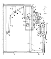
- FIGs 1, 2 and 3 are discussed below at the same time. It should be noted that the illustrations represent everything only schematically and of the entire device only the parts essential for a good understanding. The device shown is intended for step-by-step operation from the operating side, which is the left side of the figures in Figures 1 and 3 and the lower side in Figure 2.
- the frame of the entire device is denoted by 1 and includes, among other things, solid horizontal bars 2 attached to both transverse sides at the top.
- Schematically illustrated rails or guides 3 are fastened to these bars, which serve to guide a carriage 4 by means of schematically represented wheels 5 can be moved back and forth on the frame in the transverse direction on the rails or guides 3.
- Two support rollers are rotatably mounted on the carriage, the distance between which can be adjusted in a manner not shown.
- the support rollers 6 are located in a vertical plane, perpendicular to the longitudinal direction of the device. They are provided on their circumference with fixed, friction-increasing linings 7, for example with solid rubber tires.
- a pile 8 to be machined is placed in the clamping of the rolls.
- the height of piles 8 with different diameters can be set such that the axis of the pile 8 will always be approximately in the same horizontal plane.
- at least one corresponding support roller combination is located near the other end of the device for good pile support.
- This pair of support rollers is also attached to the carriage 4 in a corresponding manner.
- At least the pile 8 should be pressed firmly onto the support rollers 6 so that the cutting forces exerted by the cutting devices to be discussed below can neither throw the pile away nor set it into vibration.
- a hold-down device 9 has been attached to the frame 1, specifically a hold-down device 9 for cooperation with a pair of support rollers 6.
- the hold-down device 9 consists of a taut belt which has been placed around rotatably spaced disks 11.
- the discs 11 are mounted in a known manner on an arm 12 which is articulated at 13 about a horizontal axis parallel to the longitudinal direction of the device via a support 14 on the frame 1.
- the hinge axis 13 is located approximately at the top of a pile 8 to be machined. In the position shown in FIG. 1, the rest position, the arm 12 rests on a stop 15 which can be adjusted in a manner not shown.
- the holding-down device 9 can be moved from the position shown thus hinge upwards, as indicated by arrow 18 and shown in Fig. 3.
- a strong leaf spring 16 By means of a strong leaf spring 16, the hold-down device 9 is pressed down over a friction-reducing cover 17, for example made of a PTFE, onto the stop 15 in the idle state and onto a pile 8 to be processed during operation (FIG. 3).
- the diagram is schematic in the figures 1 and 2 indicated the cutter 19, which is intended for sharpening the pile 8.
- the axis of the milling cutter 19 lies approximately in the same plane in which the axis of the pile 8 moves during the transverse adjustment of the carriage 4.
- the milling cutter 19 will be explained in more detail below.
- the support rollers 6 of each pair are driven synchronously with the same direction of rotation by means of, for example, a chain transmission 21 from an adjustable tensioning roller 23, which tensioning roller 23 in turn is driven by a motor 24 via a chain transmission 22.
- the latter is fastened to the carriage 4 with the tensioning roller 23.
- All pairs of support rollers of the device are driven continuously synchronously with one another by known means which are not specified.
- the drives can do this can be coupled between the individual pairs of support rollers by means of, for example, axially retractable and extendable cardan shafts 231, but the drive motors can also be electrically synchronized.
- the transverse drive of the carriage 4 is provided by a schematically illustrated hydraulic or pneumatic power cylinder 25, which is articulated to a chair 26, which in turn is arranged on one of the lower beams of the frame 1.
- the outgoing rod 27 of the cylinder 25 is articulated to a lever 28, 29, which is articulated between its ends on a chair 31, which in turn is also attached to the frame 1.
- the articulated mounting of the lever 28, 29 comprises an axis 30 which runs parallel to the longitudinal direction of the frame from one end to the other end and is mounted in the chair 31 near the ends. If the axis 30 has a sufficiently high torsional rigidity, the carriage 4 will be driven in exactly the same way near its two ends, starting from a single power cylinder 25.
- the lever 29 is again articulated via a rod 32 to a coupling 33 of the carriage 4.
- Operation of the power cylinder 25, which is double-acting in the figures, but can also be single-acting, in which case it should be provided with a return spring, ensures the transverse adjustment of the carriage 4.
- This is in Fig. 1 in the extreme position on the operating side of the entire facility, where machined piles 8 are removed and new ones are inserted. From the loading and unloading position of the carriage 4 shown in FIG. 1, the latter is adjusted to the right in the figures as a result of the extension of the power cylinder 25, 27, the pile 8 to be machined first approaching the holding-down device 9 and then the milling cutter 19.
- the linkage can be designed in the manner shown.
- the angle between the lever 29 and the connecting rod 32 is acute and passes through the 90 ° range, so that with constant extension of the cylinder 25, a high feed rate occurs. If the carriage comes into the processing area L (Fig.
- means not shown such as limit switches, can be used, which control the actuation of the power cylinder.
- somewhat resilient emergency stop stops can also be provided.
- a (not shown) (hydraulic) damper can further stabilize the feed movement on the milling path.
- the pile 8 is rotated on its support rollers 6 by the drive 21-24, and this drives the hold-down rollers 11 and the belt 10, which are exposed, as they rotate.
- the milling path is covered in about 2 seconds and the pile 8 makes about 10 revolutions.
- the frame 1 carries on its upper side a longitudinal beam 51 on the rear and a longitudinal beam 52 on the operating side.
- a cross frame 47, 48, 478 is adjustably fastened thereon to support the milling cutter 19 and its drive.
- This milling frame is slightly raised so that the carriage 4 is freely movable back and forth underneath. However, it is also of low height, so that the milling cutter 19 is at the desired height, and the pile 8 can be freely moved back and forth on the milling frame.
- the milling frame can be adjusted in the longitudinal direction on the main frame 1.
- slots 50 have been made in the horizontal bars 51 and 52, in which fasteners 49 are shown with schematically represented, easy-to-use fasteners the milling frame can be attached.
- the milling cutter 19, together with its drive motor 40 and its gear 41, is mounted on a turntable 44 in a solid, rotatable manner in a known manner, not shown.
- the turntable 44 is pivotable about axis 42 and can be fixed in different angular positions with respect to the milling frame by means of a slot 43 and a fastening means 431, for example bolts and clamping nuts, which pass through it.
- the axis of rotation of the milling cutter is adjusted with respect to the axis of the pile, so that the apex angle of the tip of the pile to be machined can be adjusted.
- the turntable 44 is in turn supported by a plate 45 which is adjustably fastened on the milling frame 47, 48, 478 by means of slots 46 and associated fastening means.
- the latter setting option 46 serves above all to be able to optimally adjust the milling machine when piles with a large diameter difference have to be pointed. At the same time, a different milling diameter can be compensated for, which can be a consequence of regrinding, for example.
- the milling cutter 19 must lie above the adjustment level of the piles 8, so that the piles can be adjusted underneath and can now be pointed and folded.
- the operating device of the carriage 4 will of course have to be adapted to this, while the support 14 of the holding-down device 9 must be changed in such a way that it does not inhibit loading and unloading on this side of the device. The required The position of the milling cutter 19 is explained in more detail below with the aid of FIGS. 4, 5 and 6.
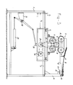
- Fig. 4 shows schematically a top view of the device described with reference to Figures 1, 2 and 3.
- the pile 8 is supported in the manner described on the pairs of support rollers 6, 7.
- Each pair is arranged in the vicinity of one end of the pile to be milled.
- the milling cutter 19 already described for producing the tip 9 is shown.
- the cutter 191 for attaching the fold 82 to the other end of the pile is shown.
- This milling cutter 191 is arranged in such a way that a bevel 82 with the usual angle of approximately 45 ° -60 ° to the axis of the pile can be produced with only a small amount of material removal.
- stop beam 60 which extends parallel to the transverse adjustment direction of the carriage 4 and against which the piles are placed during loading and on which they remain during their complete feed movement.
- the router 191 could also be replaced with a router to make two-point piles, or vice versa, the router 19 could be replaced with a router 119 or moved to a position to also fold.
- the cross conveyor system now consists of at least two endless tensioned conveyor chains, which are mounted on the frame in a known manner in the vertical plane parallel to one another and perpendicular to the axis of the piles by means of diversion wheels 67, 68.
- the upper part 65 is supported over its entire length by a runner 69 which is firmly supported on the frame by suitable supports 70.
- the hold-down chain 61, 62 is stretched around diversion rollers 63 and 64.
- the series of piles 84-89 to be machined is clamped and moved.
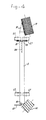
- Fig. 5c schematically shows the movement system, which will be discussed in more detail below.
- the milling cutter 19 In view of easy accessibility for exchanging and / or grinding the milling cutter 19, it is arranged essentially above the pile track.
- the bearings and the drive are in the drawings omitted, they basically agree with those described in Figures 1-3.
- the axis of rotation 20 of the milling cutter 19 is in any case at an angle ⁇ to the axis of the piles according to FIG. 5b, so that a tip 81 is milled on the piles.
- the milling cutter can be set higher than the pile length in order to obtain the blunt tip 83 indicated by a dotted line, which can be advantageous if the piles have to be driven into stony ground or the like.
- the apex angle of the pile tip is set by setting the angle ⁇ . In Fig.
- the axis 20 of the milling machine can also have an angle ⁇ to the axis of the piles in order to distribute the effective milling section L over several piles at the same time, so that the milling forces exerted on the pile are smaller and the milling load is more constant and the cutting direction will go more with the grain.
- the milling path shown in the figures corresponds to L.
- the piles 84, 85 and 86 are thus subjected to milling in this snapshot and should therefore be clamped sufficiently firmly between the conveyor belt and the hold-down belt.
- the straps are provided on their load-bearing side with fine sharp serrations or the like, as indicated schematically with 651, in order to grip the piles non-slip nonetheless without any significant damage to the pile surface.
- the piles rotate about their own axis during their feed movement under the milling machine.
- the upper part 65 of the conveyor belt with a linear speed
- the circumferential speed at which the pile rotates is approximately the same as
- is small and is: To mill the average spruce wood pile, each pile makes about 10 revolutions on the milling section L and covers this section in about 2 seconds. It follows from the above that the cooperating conveyor and hold-down belt are driven individually with the same direction of rotation for the diversion rollers 63, 64 and 67, 68, but with a slightly different value, in order to achieve a resulting feed rate
- Resilient sliding shoes are suitable for this. They are based on a frame part schematically indicated with 71 with sufficient strength, which is height-adjustable with the entire hold-down band, as indicated schematically with h. On the milling section L, however, the piles, in this case 84, 85 and 86 individually, should be firmly pressed on.
- hydraulically or pneumatically operated power cylinders 73 can be used, which exert such a hold-down force that they can overcome the pretension of the hold-down chain. In this way, piles of different thicknesses lying next to each other can be reliably controlled during the milling process, both in terms of their own rotation and in terms of their feed.
- Milling with long cutting edges that form wood shavings are less suitable, because of their greater sensitivity to knots in wood, for example. It will also be clear to the person skilled in the art that correct, right-angled feeding of the piles to the conveyor chain is required, but various known devices must be used for this purpose, which therefore need not be described and illustrated. In the manner already described, the continuous device can also be designed to make longer piles into two shorter ones.
Landscapes
- Engineering & Computer Science (AREA)
- Life Sciences & Earth Sciences (AREA)
- Mechanical Engineering (AREA)
- Manufacturing & Machinery (AREA)
- Wood Science & Technology (AREA)
- Forests & Forestry (AREA)
- Grinding Of Cylindrical And Plane Surfaces (AREA)
- Milling, Drilling, And Turning Of Wood (AREA)
- Finish Polishing, Edge Sharpening, And Grinding By Specific Grinding Devices (AREA)
Applications Claiming Priority (2)
| Application Number | Priority Date | Filing Date | Title |
|---|---|---|---|
| NL8503288A NL8503288A (nl) | 1985-11-27 | 1985-11-27 | Inrichting voor het punten en/of kronen van palen. |
| NL8503288 | 1985-11-27 |
Publications (1)
| Publication Number | Publication Date |
|---|---|
| EP0226237A1 true EP0226237A1 (fr) | 1987-06-24 |
Family
ID=19846936
Family Applications (1)
| Application Number | Title | Priority Date | Filing Date |
|---|---|---|---|
| EP86201984A Withdrawn EP0226237A1 (fr) | 1985-11-27 | 1986-11-12 | Dispositif pour appointer et/ou tronçonner des poteaux |
Country Status (3)
| Country | Link |
|---|---|
| EP (1) | EP0226237A1 (fr) |
| DE (1) | DE8631264U1 (fr) |
| NL (1) | NL8503288A (fr) |
Cited By (2)
| Publication number | Priority date | Publication date | Assignee | Title |
|---|---|---|---|---|
| AT465U1 (de) * | 1994-11-22 | 1995-11-27 | Fuerlinger August | Entrindungsmaschine |
| IT201800007912A1 (it) * | 2018-08-07 | 2020-02-07 | Scm Group Spa | Macchina utensile con sistema perfezionato per la movimentazione di pannelli o simili. |
Families Citing this family (1)
| Publication number | Priority date | Publication date | Assignee | Title |
|---|---|---|---|---|
| NL1029944C2 (nl) * | 2005-09-13 | 2007-03-15 | Edward De Jong | Houtbewerkingsinrichting. |
Citations (19)
| Publication number | Priority date | Publication date | Assignee | Title |
|---|---|---|---|---|
| NL123244C (fr) * | 1959-03-25 | 1900-01-01 | ||
| US1621963A (en) * | 1923-06-04 | 1927-03-22 | Nat Pole & Treating Company | Pole-puncturing machine |
| US1744875A (en) * | 1927-12-28 | 1930-01-28 | William W Edwards | Guard and workholder for planers |
| US1955437A (en) * | 1932-03-12 | 1934-04-17 | Harry E Oeser | Pole planing machine |
| US1993064A (en) * | 1934-04-02 | 1935-03-05 | Blanc Eugene Le | Machine for grinding shuttle points |
| FR815816A (fr) * | 1934-03-22 | 1937-07-23 | Appointeuse | |
| GB550902A (en) * | 1941-12-01 | 1943-01-29 | Tubes Ltd | A machine for trimming the ends of cylindrical metal tubes or bars |
| US2766785A (en) * | 1955-04-25 | 1956-10-16 | Armand A Joyal | Wood working jig |
| US2840127A (en) * | 1954-06-05 | 1958-06-24 | Abitibi Power & Paper Co | Apparatus for making wood shavings |
| US3451449A (en) * | 1967-02-06 | 1969-06-24 | Bouma Post Yards | Post pointing and capping apparatus |
| CA911861A (en) * | 1972-03-20 | 1972-10-10 | Domtar Limited | Post domer |
| DE2121943A1 (de) * | 1971-05-04 | 1972-11-23 | H. Brunotte KG, 3200 Hildesheim | Vorrichtung zum Anschleifen von Nagelspitzen |
| FR2261849A1 (en) * | 1967-10-27 | 1975-09-19 | Hardtle Wilhelm | Round log debarking machine - has belts in V-pattern supporting and rotating log during machining |
| US4048761A (en) * | 1976-07-09 | 1977-09-20 | Champion International Corporation | Paper stick pointing apparatus |
| DE2822771A1 (de) * | 1978-05-24 | 1979-12-06 | Pauli Josef Bauschlosserei | Vorrichtung zum herstellen von an den stirnseiten angefasten duebeln aus holzstaeben |
| US4363342A (en) * | 1977-11-04 | 1982-12-14 | Bruks Mekaniska Ab | Log milling apparatus |
| DE3134823A1 (de) * | 1981-09-03 | 1983-03-17 | G.A. Pfleiderer GmbH & Co KG, 8430 Neumarkt | Verfahren und vorrichtung zum anfasen der stirnenden von rundhoelzern |
| WO1984002105A1 (fr) * | 1982-11-30 | 1984-06-07 | John Flessum | Machine pour enlever des parties de racines epaisses des arbres |
| FR2541618A1 (fr) * | 1983-02-25 | 1984-08-31 | Kombak Maschinenfabrik Gmbh Co | Procede et dispositif pour fraiser la naissance des racines sur les grumes |
-
1985
- 1985-11-27 NL NL8503288A patent/NL8503288A/nl not_active Application Discontinuation
-
1986
- 1986-11-12 EP EP86201984A patent/EP0226237A1/fr not_active Withdrawn
- 1986-11-26 DE DE19868631264 patent/DE8631264U1/de not_active Expired
Patent Citations (19)
| Publication number | Priority date | Publication date | Assignee | Title |
|---|---|---|---|---|
| US1621963A (en) * | 1923-06-04 | 1927-03-22 | Nat Pole & Treating Company | Pole-puncturing machine |
| US1744875A (en) * | 1927-12-28 | 1930-01-28 | William W Edwards | Guard and workholder for planers |
| US1955437A (en) * | 1932-03-12 | 1934-04-17 | Harry E Oeser | Pole planing machine |
| FR815816A (fr) * | 1934-03-22 | 1937-07-23 | Appointeuse | |
| US1993064A (en) * | 1934-04-02 | 1935-03-05 | Blanc Eugene Le | Machine for grinding shuttle points |
| GB550902A (en) * | 1941-12-01 | 1943-01-29 | Tubes Ltd | A machine for trimming the ends of cylindrical metal tubes or bars |
| US2840127A (en) * | 1954-06-05 | 1958-06-24 | Abitibi Power & Paper Co | Apparatus for making wood shavings |
| US2766785A (en) * | 1955-04-25 | 1956-10-16 | Armand A Joyal | Wood working jig |
| NL123244C (fr) * | 1959-03-25 | 1900-01-01 | ||
| US3451449A (en) * | 1967-02-06 | 1969-06-24 | Bouma Post Yards | Post pointing and capping apparatus |
| FR2261849A1 (en) * | 1967-10-27 | 1975-09-19 | Hardtle Wilhelm | Round log debarking machine - has belts in V-pattern supporting and rotating log during machining |
| DE2121943A1 (de) * | 1971-05-04 | 1972-11-23 | H. Brunotte KG, 3200 Hildesheim | Vorrichtung zum Anschleifen von Nagelspitzen |
| CA911861A (en) * | 1972-03-20 | 1972-10-10 | Domtar Limited | Post domer |
| US4048761A (en) * | 1976-07-09 | 1977-09-20 | Champion International Corporation | Paper stick pointing apparatus |
| US4363342A (en) * | 1977-11-04 | 1982-12-14 | Bruks Mekaniska Ab | Log milling apparatus |
| DE2822771A1 (de) * | 1978-05-24 | 1979-12-06 | Pauli Josef Bauschlosserei | Vorrichtung zum herstellen von an den stirnseiten angefasten duebeln aus holzstaeben |
| DE3134823A1 (de) * | 1981-09-03 | 1983-03-17 | G.A. Pfleiderer GmbH & Co KG, 8430 Neumarkt | Verfahren und vorrichtung zum anfasen der stirnenden von rundhoelzern |
| WO1984002105A1 (fr) * | 1982-11-30 | 1984-06-07 | John Flessum | Machine pour enlever des parties de racines epaisses des arbres |
| FR2541618A1 (fr) * | 1983-02-25 | 1984-08-31 | Kombak Maschinenfabrik Gmbh Co | Procede et dispositif pour fraiser la naissance des racines sur les grumes |
Cited By (3)
| Publication number | Priority date | Publication date | Assignee | Title |
|---|---|---|---|---|
| AT465U1 (de) * | 1994-11-22 | 1995-11-27 | Fuerlinger August | Entrindungsmaschine |
| IT201800007912A1 (it) * | 2018-08-07 | 2020-02-07 | Scm Group Spa | Macchina utensile con sistema perfezionato per la movimentazione di pannelli o simili. |
| EP3608051A1 (fr) * | 2018-08-07 | 2020-02-12 | SCM Group S.p.A. | Machine-outil avec système amélioré pour déplacer des panneaux ou similaire |
Also Published As
| Publication number | Publication date |
|---|---|
| DE8631264U1 (de) | 1987-04-09 |
| NL8503288A (nl) | 1987-06-16 |
Similar Documents
| Publication | Publication Date | Title |
|---|---|---|
| EP0443122B1 (fr) | Scie à ruban vertical | |
| DE3724321B4 (de) | Zweischnitt-Bandsägemaschine | |
| DE69207837T2 (de) | Spannvorrichtung zur Halterung von Rollen durch Druckbefestigung bei Schneidmaschinen zur Herstellung von Toilettenpapier und dergleichen | |
| DE2548771C3 (de) | Vorschub- und Spanneinrichtung für eine Trennmaschine | |
| CH667609A5 (de) | Maschinenschere. | |
| DE2507449A1 (de) | Maschinenschere | |
| DE3927275C2 (fr) | ||
| EP1810769A1 (fr) | Machine à usiner des panneaux avec unité de sciage | |
| DE2905786A1 (de) | Furnier-schaelmaschine | |
| DE3517146A1 (de) | Maschine zur herstellung von keilzinken-verbindungen | |
| DE29880130U1 (de) | Führungsvorrichtung für ein Sägeblatt | |
| CH692027A5 (de) | Verfahren und Gerät zum Handhaben einer Bandsäge während Herstell- oder Reparaturvorgängen. | |
| DE4341864C2 (de) | Vorrichtung zum Entfernen von Schweißwülsten von Kunststoffpaletten und dabei verwendete Schneidvorrichtungen | |
| EP0226237A1 (fr) | Dispositif pour appointer et/ou tronçonner des poteaux | |
| DE19547193C2 (de) | Verfahren und Vorrichtung zum Einschneiden eines Baumstammes | |
| DE2542647C2 (de) | Vorrichtung zum Schneiden von Holzstücken | |
| DE4326890A1 (de) | Vorrichtung zum Schleifen der Kanten von platten- oder tafelförmigen Werkstücken | |
| EP0400530A2 (fr) | Dispositif de tronçonnage de pièces | |
| DE2752648A1 (de) | Vorrichtung zum schneiden einer einfuehrungsspitze an warenbahnen | |
| DE459501C (de) | Maschine zum Schleifen der Zaehne von Saegeblaettern | |
| DE10013970A1 (de) | Vorrichtung zum Bearbeiten stabförmiger Holzelemente | |
| DE3100644A1 (de) | Vorrichtung zum spalten von holzscheiten | |
| DE2722290A1 (de) | Vorrichtung zum selbsttaetigen bearbeiten der kanten bzw. raender eines plattenfoermigen werkstuecks | |
| DE532070C (de) | Maschine zum Zurichten von ebenen Druckplatten | |
| DE1703806B2 (de) | Maschine zum zertrennen von holzkoerpern, insbesondere halbstaemmen, in einzelne rinnenfoermige elemente |
Legal Events
| Date | Code | Title | Description |
|---|---|---|---|
| PUAI | Public reference made under article 153(3) epc to a published international application that has entered the european phase |
Free format text: ORIGINAL CODE: 0009012 |
|
| AK | Designated contracting states |
Kind code of ref document: A1 Designated state(s): AT BE CH DE ES FR GB GR IT LI LU NL SE |
|
| 17P | Request for examination filed |
Effective date: 19871214 |
|
| 17Q | First examination report despatched |
Effective date: 19890202 |
|
| STAA | Information on the status of an ep patent application or granted ep patent |
Free format text: STATUS: THE APPLICATION IS DEEMED TO BE WITHDRAWN |
|
| 18D | Application deemed to be withdrawn |
Effective date: 19900523 |