EP0226251A1 - A device for inserting a drainage wick into the ground - Google Patents
A device for inserting a drainage wick into the ground Download PDFInfo
- Publication number
- EP0226251A1 EP0226251A1 EP19860202200 EP86202200A EP0226251A1 EP 0226251 A1 EP0226251 A1 EP 0226251A1 EP 19860202200 EP19860202200 EP 19860202200 EP 86202200 A EP86202200 A EP 86202200A EP 0226251 A1 EP0226251 A1 EP 0226251A1
- Authority
- EP
- European Patent Office
- Prior art keywords
- mast
- tube
- wick
- ground
- cylinder
- Prior art date
- Legal status (The legal status is an assumption and is not a legal conclusion. Google has not performed a legal analysis and makes no representation as to the accuracy of the status listed.)
- Granted
Links
- 238000003780 insertion Methods 0.000 abstract description 6
- 230000037431 insertion Effects 0.000 abstract description 6
- XLYOFNOQVPJJNP-UHFFFAOYSA-N water Substances O XLYOFNOQVPJJNP-UHFFFAOYSA-N 0.000 abstract description 5
- 238000004904 shortening Methods 0.000 abstract description 2
- 239000002689 soil Substances 0.000 description 4
- 238000010276 construction Methods 0.000 description 1
- 238000006073 displacement reaction Methods 0.000 description 1
- 230000000694 effects Effects 0.000 description 1
- 238000000605 extraction Methods 0.000 description 1
- 239000012530 fluid Substances 0.000 description 1
- 238000009434 installation Methods 0.000 description 1
- 238000000034 method Methods 0.000 description 1
Images


Classifications
-
- E—FIXED CONSTRUCTIONS
- E02—HYDRAULIC ENGINEERING; FOUNDATIONS; SOIL SHIFTING
- E02D—FOUNDATIONS; EXCAVATIONS; EMBANKMENTS; UNDERGROUND OR UNDERWATER STRUCTURES
- E02D3/00—Improving or preserving soil or rock, e.g. preserving permafrost soil
- E02D3/02—Improving by compacting
- E02D3/10—Improving by compacting by watering, draining, de-aerating or blasting, e.g. by installing sand or wick drains
- E02D3/103—Improving by compacting by watering, draining, de-aerating or blasting, e.g. by installing sand or wick drains by installing wick drains or sand bags
Definitions
- the invention concerns a device for inserting into the ground a drainage wick consisting of a profiled core and water permeable sleeve, said device consisting mainly of a mobile machine such as a backhoe, with a mast, and attached to the mast a rectangular tube, holding a drainage wick, and being able to move up and down along the mast in a vertical manner.
- a drainage wick In order to insert water or to de-water soil it is customary to insert a drainage wick vertically in the soil, to for example a depth of 10 m.
- a drainage wick inserted by means of a tube, such tube being driven into the ground.
- the drainage wick When such tube is extracted from the ground, the drainage wick remains in the soil, the soil pressurizes against the wick, and water may travel through the permeable sleeve of the wick along the wick either up or down, depending on the function.
- This invention has for its object to resolve this problem by providing means to inserting wicks into the groundat a much faster rate.
- the device according to the invention is distinguished in that the tube inserting the wick is inserted into the ground by a hydraulic cilinder which is supported on the mast.
- This cilinder may be hydraulic or pneumatic with the advantage that such cilinder will apply a continuous driving force to the tube with the result that the drainage wick will be inserted into the ground at a much faster rate.
- the device can be built lighter and may be used by attaching it to a standard hydraulic backhoe, having the backhoe bucket removed, and the linkages and hydraulic arm attached to the mast with the installation tube. Such a setup will be far more mobile than the traditional pile driving leads, and maybe moved on and around the job site much more easily than traditional equipment.
- the cylinder is preferably provided with a sheave carrier around which the cable is formed.
- a sheave carrier around which the cable is formed.
- the invention furthermore provides for two cylinders placed in series (one after the other).
- two cylinders placed in series (one after the other).
- it will be possible to keep the shaft diameter of the cylinder relatively small, so that small hydraulic capacity is needed whilst providing for large displacement.
- the equipment as depicted in the drawings consists principally of a mobile machine 1, carrying a mast 2, wherein a tube 3 may be moved up and down in a vertical sense.
- the mobile equipment 1 can be any type of equipment, such as a hydraulic backhoe or excavator, in figure 1 only the arm of which is schematically shown. This arm is attached to the mast 2 with connector 4 which is journalled around pin 5 attached to the arm.
- a hydraulic cylinder 6 of the device is able to bring the connector piece and thereby the mast 2 about pin 5 in a vertical position.
- the mast 2 is furthermore provided with a pair of hydraulic cylinders 7 and 8 connected in series, with one end of the bottom cylinder 8 supported on the mast 2 whilst the cylinder rod of the upper cylinder 7 supports the sheave housing for block 9.
- a housing 10 and 11 At both ends of the mast there is a housing 10 and 11, in each of which a pair of sheaves 12 and 13 are mounted.
- the system comprises a flexible element 14, fastened to the top of the mast 2, and led around the upper sheave of block 9, around the sheave system 12, and finally secured to the tube 3.
- a similar flexible element 16 is secured to the bottom of the mast 2, led around the bottom block of sheave 9, furthermore around the bottom sheave system 13 and also secured to tube 3.
- the wick 17 By folding around or attaching an anchor plate, the wick 17 will be carried into the ground in the direction of arrow P1, until tube 3 is entirely inserted into the ground. By means of extraction of tube 3 the folded over end of the wick 17 shall remain in the ground and will allow the tube 3 to move upwards freely. As soon as tube 3 is entirely extracted the wick 17 may be cut off from the bottom of the tube 3 and subsequently the whole process may be repeated.
- the insertion of tube 3 is made possible by applying power to cylinder 7 and 8 either simultaneously or consecutively.
- the supply of power to cylinders 7 and 8 is provided by the main hydraulics of the hydraulic machine 1 and shall provide for the action of cylinder 7 and 8 to cause the equipment to produce the cycle starting from a position as shown in figure 1.
- cylinder 7 shall move upwards relative to cylinder 8 and block 9 will move relative to cylinder 7 and 8.
- the right part of flexible element 16 will move at twice the rate of block 9 while inserting tube 3.
- a counter weight 18 may be attached to mast 2.
- the mast consists of a hollow square tube, which is provided with an opening 19 at the bottom with a guide roll 20, which provides for the smooth carriage of the wick 17.
- This roll of wick 17 may spin freely on carrier 21 which is suitably attached to the mast opposite said hydraulic implement 1.
- the mast is fitted at the adjacent side with a guide rail 22 (see figure 3) whereby a guide block 23 can move up and down.
- This guide block is attached to the bottom end of the upper cylinder 7 as well via a connector piece 24, pivotably connected to the cylinder rod 8' of the bottom cylinder.
- the guide rail 22 therefore provides for an optimum power distribution for both cylinders 7 and 8, so that slender and relatively small cylinder diameters may be used. This speeds up the operation of the equipment substantially because only a relatively small amount of hydraulic fluid, like oil, is needed.
- the mast 2 is fitted on the opposite side with a similar guide rail 25, along which the tube 3 may be moved up and down.
- tube 3 has been fitted with a T-rail 26, which fits into the guide rail 25 comprising two L-profiles.
- the equipment may be embodied relatively light, and is capable of being moved and set up at a very faste rate. It has been proven that the cycle time to inserting drainage wick may be reduced to within 1/3 of the usual insertion time.
Landscapes
- Engineering & Computer Science (AREA)
- Structural Engineering (AREA)
- Life Sciences & Earth Sciences (AREA)
- General Life Sciences & Earth Sciences (AREA)
- Soil Sciences (AREA)
- Environmental & Geological Engineering (AREA)
- Agronomy & Crop Science (AREA)
- Mining & Mineral Resources (AREA)
- Paleontology (AREA)
- Civil Engineering (AREA)
- General Engineering & Computer Science (AREA)
- Investigation Of Foundation Soil And Reinforcement Of Foundation Soil By Compacting Or Drainage (AREA)
- Earth Drilling (AREA)
- Catching Or Destruction (AREA)
- Investigating Or Analysing Biological Materials (AREA)
Abstract
Description
- The invention concerns a device for inserting into the ground a drainage wick consisting of a profiled core and water permeable sleeve, said device consisting mainly of a mobile machine such as a backhoe, with a mast, and attached to the mast a rectangular tube, holding a drainage wick, and being able to move up and down along the mast in a vertical manner.
- In order to insert water or to de-water soil it is customary to insert a drainage wick vertically in the soil, to for example a depth of 10 m. Such a drainage wick inserted by means of a tube, such tube being driven into the ground. When such tube is extracted from the ground, the drainage wick remains in the soil, the soil pressurizes against the wick, and water may travel through the permeable sleeve of the wick along the wick either up or down, depending on the function.
- It is common practice to drive the aforementioned tube into the ground by means of pile driving leads. Such leads of themselves are relatively heavy, and the driving activity is relatively slow. As drainage wicks are inserted at a frequency of 2 to 3 meters, for example on a dike pad, relatively much time is needed in order to introduce the number of wicks required.
- This invention has for its object to resolve this problem by providing means to inserting wicks into the groundat a much faster rate. The device according to the invention is distinguished in that the tube inserting the wick is inserted into the ground by a hydraulic cilinder which is supported on the mast. This cilinder may be hydraulic or pneumatic with the advantage that such cilinder will apply a continuous driving force to the tube with the result that the drainage wick will be inserted into the ground at a much faster rate. Moreover the device can be built lighter and may be used by attaching it to a standard hydraulic backhoe, having the backhoe bucket removed, and the linkages and hydraulic arm attached to the mast with the installation tube. Such a setup will be far more mobile than the traditional pile driving leads, and maybe moved on and around the job site much more easily than traditional equipment.
- In order to obtain an optimum power distribution on the cylinder, which must be relatively long, it is desirable to fix a flexible attachment such as a cable or chain, between the cylinder and the tube, this flexible attachment being fixed to a sheave on the mast.
- The cylinder is preferably provided with a sheave carrier around which the cable is formed. Hereby is achieved a two times or a multiple insertion speed, in comparison with the capacity or stroke of the cylinder thus again shortening the time needed to insert the tube.
- The invention furthermore provides for two cylinders placed in series (one after the other). Hereby it will be possible to keep the shaft diameter of the cylinder relatively small, so that small hydraulic capacity is needed whilst providing for large displacement. Because of the slenderness of the hydraulic cylinders, it is preferred to provide for a guide path for each of the cylinders attached to the mast.
- The invention is further described in the detailed description of an embodiment as depicted and explained below. In the drawings is:
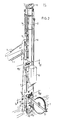
- Fig. 1 a schematic side view of the various parts of the equipment according to the invention showing the cable connections, and tube travel,
- Fig. 2 a perspective view of the device according to a first embodiment,
- Fig. 3 & 4, each a perspective view of a part of the device in figure 2 according to the cross sections III-III, IV-IV in figure 2 respectively.
- The equipment as depicted in the drawings consists principally of a
mobile machine 1, carrying a mast 2, wherein atube 3 may be moved up and down in a vertical sense. It should be noted that themobile equipment 1 can be any type of equipment, such as a hydraulic backhoe or excavator, in figure 1 only the arm of which is schematically shown. This arm is attached to the mast 2 with connector 4 which is journalled aroundpin 5 attached to the arm. A hydraulic cylinder 6 of the device is able to bring the connector piece and thereby the mast 2 aboutpin 5 in a vertical position. - The mast 2 is furthermore provided with a pair of
hydraulic cylinders 7 and 8 connected in series, with one end of the bottom cylinder 8 supported on the mast 2 whilst the cylinder rod of theupper cylinder 7 supports the sheave housing for block 9. At both ends of the mast there is ahousing 10 and 11, in each of which a pair ofsheaves 12 and 13 are mounted. The system comprises aflexible element 14, fastened to the top of the mast 2, and led around the upper sheave of block 9, around thesheave system 12, and finally secured to thetube 3. A similarflexible element 16 is secured to the bottom of the mast 2, led around the bottom block of sheave 9, furthermore around the bottom sheave system 13 and also secured totube 3. - From a supply
roller drainage wick 17 is led upwards via the mast 2 and subsequently inserted intotube 3, so that the bottom end of the wick protrudes from the lower end of thetube 3. - By folding around or attaching an anchor plate, the
wick 17 will be carried into the ground in the direction of arrow P1, untiltube 3 is entirely inserted into the ground. By means of extraction oftube 3 the folded over end of thewick 17 shall remain in the ground and will allow thetube 3 to move upwards freely. As soon astube 3 is entirely extracted thewick 17 may be cut off from the bottom of thetube 3 and subsequently the whole process may be repeated. - The insertion of
tube 3 is made possible by applying power tocylinder 7 and 8 either simultaneously or consecutively. The supply of power tocylinders 7 and 8 is provided by the main hydraulics of thehydraulic machine 1 and shall provide for the action ofcylinder 7 and 8 to cause the equipment to produce the cycle starting from a position as shown in figure 1. Thuscylinder 7 shall move upwards relative to cylinder 8 and block 9 will move relative tocylinder 7 and 8. As the block 9 moves upwards, the right part offlexible element 16 will move at twice the rate of block 9 while insertingtube 3. - In order to extract
tube 3 from the ground,cylinders 7 and 8 must be activated inversely, so thatflexible element 14 will extracttube 3 twice as fast upwards as the movement of block 9. - Finally it must be noted in order to achieve sufficient counter pressure to inserting the
tube 3, acounter weight 18 may be attached to mast 2. - Actual construction details are shown in figures 2 and 3. From these figures it is clear that the mast consists of a hollow square tube, which is provided with an
opening 19 at the bottom with aguide roll 20, which provides for the smooth carriage of thewick 17. This roll ofwick 17 may spin freely oncarrier 21 which is suitably attached to the mast opposite saidhydraulic implement 1. - The mast is fitted at the adjacent side with a guide rail 22 (see figure 3) whereby a
guide block 23 can move up and down. This guide block is attached to the bottom end of theupper cylinder 7 as well via aconnector piece 24, pivotably connected to the cylinder rod 8' of the bottom cylinder. - Similarly block 9 could be inserted into the
guide rail 22. Theguide rail 22 therefore provides for an optimum power distribution for bothcylinders 7 and 8, so that slender and relatively small cylinder diameters may be used. This speeds up the operation of the equipment substantially because only a relatively small amount of hydraulic fluid, like oil, is needed. - The mast 2 is fitted on the opposite side with a
similar guide rail 25, along which thetube 3 may be moved up and down. To thisend tube 3 has been fitted with a T-rail 26, which fits into theguide rail 25 comprising two L-profiles. - From the above it will become obvious that the equipment may be embodied relatively light, and is capable of being moved and set up at a very faste rate. It has been proven that the cycle time to inserting drainage wick may be reduced to within 1/3 of the usual insertion time.
- This invention is not restricted to the above described embodiment. For example the block 9 does not to be provided for but the cable may be attached directly to cylinder head of 7, whereby the multiple insertion speed is obviously eliminated, but the slender hydraulic cylinders may be maintained.
- Alternatively it is also possible to attach multiple sheaves therefore providing for a four or more multiple insertion speed.
Claims (5)
Priority Applications (1)
| Application Number | Priority Date | Filing Date | Title |
|---|---|---|---|
| AT86202200T ATE63349T1 (en) | 1985-12-09 | 1986-12-05 | DEVICE FOR INSTALLING A DRAINAGE TAPE INTO THE GROUND. |
Applications Claiming Priority (2)
| Application Number | Priority Date | Filing Date | Title |
|---|---|---|---|
| NL8503390 | 1985-12-09 | ||
| NL8503390A NL8503390A (en) | 1985-12-09 | 1985-12-09 | DEVICE FOR GROUNDING A DRAINAGE RIBBON. |
Publications (2)
| Publication Number | Publication Date |
|---|---|
| EP0226251A1 true EP0226251A1 (en) | 1987-06-24 |
| EP0226251B1 EP0226251B1 (en) | 1991-05-08 |
Family
ID=19846985
Family Applications (1)
| Application Number | Title | Priority Date | Filing Date |
|---|---|---|---|
| EP86202200A Expired - Lifetime EP0226251B1 (en) | 1985-12-09 | 1986-12-05 | A device for inserting a drainage wick into the ground |
Country Status (10)
| Country | Link |
|---|---|
| US (1) | US4755080A (en) |
| EP (1) | EP0226251B1 (en) |
| JP (1) | JPH0654004B2 (en) |
| AT (1) | ATE63349T1 (en) |
| CA (1) | CA1261638A (en) |
| DE (1) | DE3679162D1 (en) |
| ES (1) | ES2022120B3 (en) |
| FI (1) | FI86903C (en) |
| GR (1) | GR3002019T3 (en) |
| NL (1) | NL8503390A (en) |
Cited By (6)
| Publication number | Priority date | Publication date | Assignee | Title |
|---|---|---|---|---|
| EP0672795A1 (en) * | 1994-03-15 | 1995-09-20 | Geotechnics Holland B.V. | Drainage wick inserting device |
| EP1369534A1 (en) | 2002-06-06 | 2003-12-10 | Geotechnics Holland B.V. | Device for and method of inserting a drainage material into the ground |
| EP1369533A1 (en) | 2002-06-06 | 2003-12-10 | Geotechnics Holland B.V. | Drainage material |
| NL1033363C2 (en) * | 2006-12-29 | 2008-07-01 | Bos & Kalis Baggermaatsch | Device for introducing an elongated, flexible element, such as a drainage element, into a bottom. |
| US7566188B2 (en) | 2006-09-28 | 2009-07-28 | Freyssinet | Method and device for inserting a drainage wick |
| US7736091B2 (en) | 2006-09-28 | 2010-06-15 | Freyssinet | Method and device for inserting a drainage wick |
Families Citing this family (33)
| Publication number | Priority date | Publication date | Assignee | Title |
|---|---|---|---|---|
| SE456431B (en) * | 1987-02-06 | 1988-10-03 | Bo Andreasson | PALNINGSMETOD |
| FR2641015B1 (en) * | 1988-12-26 | 1991-07-19 | Morillon Corvol Courbot | |
| US5012873A (en) * | 1989-07-14 | 1991-05-07 | Ampsco Corporation | Device for forcing a reflective highway post into the ground |
| US5040927A (en) * | 1990-05-29 | 1991-08-20 | Wickberg Norman E | Pressure driver for pilings |
| US5213449C1 (en) * | 1991-07-08 | 2001-07-03 | T Richard Morris | Apparatus for inserting wick drains into the earth |
| US5304015A (en) * | 1993-02-17 | 1994-04-19 | Sonomura Roy N | Pile grabber apparatus |
| US5439326A (en) * | 1993-04-14 | 1995-08-08 | Geotechnics America, Inc. | Apparatus for inserting prefabricated vertical drains into the earth |
| US5658091A (en) * | 1996-01-29 | 1997-08-19 | Geotechnics America, Inc. | Apparatus for inserting prefabricated vertical drains into the earth |
| US6039508A (en) * | 1997-07-25 | 2000-03-21 | American Piledriving Equipment, Inc. | Apparatus for inserting elongate members into the earth |
| US6431795B2 (en) | 1997-07-25 | 2002-08-13 | American Piledriving Equipment, Inc. | Systems and methods for inserting wick drain material |
| US6543966B2 (en) | 1997-07-25 | 2003-04-08 | American Piledriving Equipment, Inc. | Drive system for inserting and extracting elongate members into the earth |
| NL1009998C2 (en) * | 1998-09-02 | 2000-03-15 | Ooms Avenhorn Holding Bv | Method and device for installing interconnected vertical pipes in the ground. |
| US6447036B1 (en) | 1999-03-23 | 2002-09-10 | American Piledriving Equipment, Inc. | Pile clamp systems and methods |
| US6179527B1 (en) | 1999-04-05 | 2001-01-30 | R. Robert Goughnour | Apparatus for inserting flexible members into the earth |
| US6142711A (en) * | 1999-04-05 | 2000-11-07 | Goughnour; R. Robert | Vibrator having a rotating and oscillating housing |
| NL1020117C2 (en) * | 2002-03-06 | 2003-09-10 | Tms Technical & Maritime Servi | Vertical drainage device mounted on moving carriage, can be erected to rear of carriage and transported in position above carriage |
| US7694747B1 (en) | 2002-09-17 | 2010-04-13 | American Piledriving Equipment, Inc. | Preloaded drop hammer for driving piles |
| NZ522158A (en) * | 2002-10-21 | 2005-05-27 | Rocktec Ltd | A locking mechanism |
| KR100482623B1 (en) * | 2002-12-07 | 2005-04-14 | (주) 지티이 | Apparatus for driving drain-board of crane for reinforcing ground of weakness |
| US20040188118A1 (en) * | 2003-03-26 | 2004-09-30 | Mcphee Robert | Vibratory post driving device |
| US7854571B1 (en) | 2005-07-20 | 2010-12-21 | American Piledriving Equipment, Inc. | Systems and methods for handling piles |
| KR100839751B1 (en) * | 2008-02-01 | 2008-06-19 | 김간주 | Drain repositioning device to embed drain material in ground without anchor plate |
| US8763719B2 (en) | 2010-01-06 | 2014-07-01 | American Piledriving Equipment, Inc. | Pile driving systems and methods employing preloaded drop hammer |
| US8434969B2 (en) | 2010-04-02 | 2013-05-07 | American Piledriving Equipment, Inc. | Internal pipe clamp |
| US8776627B2 (en) * | 2012-05-02 | 2014-07-15 | Amik Oilfield Equipment And Rentals Ltd. | Reciprocating pump drive assembly |
| US9249551B1 (en) | 2012-11-30 | 2016-02-02 | American Piledriving Equipment, Inc. | Concrete sheet pile clamp assemblies and methods and pile driving systems for concrete sheet piles |
| US9371624B2 (en) | 2013-07-05 | 2016-06-21 | American Piledriving Equipment, Inc. | Accessory connection systems and methods for use with helical piledriving systems |
| US10392871B2 (en) | 2015-11-18 | 2019-08-27 | American Piledriving Equipment, Inc. | Earth boring systems and methods with integral debris removal |
| US9957684B2 (en) | 2015-12-11 | 2018-05-01 | American Piledriving Equipment, Inc. | Systems and methods for installing pile structures in permafrost |
| US10273646B2 (en) | 2015-12-14 | 2019-04-30 | American Piledriving Equipment, Inc. | Guide systems and methods for diesel hammers |
| US10538892B2 (en) | 2016-06-30 | 2020-01-21 | American Piledriving Equipment, Inc. | Hydraulic impact hammer systems and methods |
| US12129623B2 (en) | 2021-03-31 | 2024-10-29 | American Piledriving Equipment, Inc. | Segmented ram systems and methods for hydraulic impact hammers |
| US12606972B2 (en) | 2024-02-07 | 2026-04-21 | American Piledriving Equipment, Inc. | Variable moment vibratory systems and methods |
Citations (9)
| Publication number | Priority date | Publication date | Assignee | Title |
|---|---|---|---|---|
| NL42349C (en) * | 1900-01-01 | |||
| FR838717A (en) * | 1937-07-13 | 1939-03-14 | Device for pulling formwork, columns and other similar devices from the ground, applicable to bells and scaffoldings for sounding or driving sheet piles | |
| NL65252C (en) * | 1939-01-25 | 1950-02-15 | Walter Kjellman | |
| US3172485A (en) * | 1963-05-07 | 1965-03-09 | Raymond Int Inc | Downcrowding arrangement for pile driving and the like |
| US3891186A (en) * | 1972-11-27 | 1975-06-24 | Linden Alimak Ab | Device for inserting drains into the ground |
| NL7710385A (en) * | 1976-09-23 | 1978-03-29 | Krings Josef | APPARATUS FOR PULLING FORMWORK WALLS, PLATES OR DAMBOARDS FOR EXCAVATIONS. |
| NL7707303A (en) * | 1977-07-01 | 1979-01-03 | Nico Gerhard Cortlever | Earth drain insertion method - involves placing drain in injection pipe, forced into ground by ram block |
| NL7805153A (en) * | 1978-05-12 | 1979-11-14 | Adrianus Johannes Van Bragt | Vertical soil drainage component acting through different strata - has central portion formed by transverse partitions and walls bearing against permeable layers |
| GB2028902A (en) * | 1978-08-29 | 1980-03-12 | Spence D | Hydraulically Powered Attachment for a Tractor |
Family Cites Families (10)
| Publication number | Priority date | Publication date | Assignee | Title |
|---|---|---|---|---|
| US1973197A (en) * | 1932-07-11 | 1934-09-11 | Harold U Baker | Hydraulic drilling device |
| US2476390A (en) * | 1947-05-26 | 1949-07-19 | John H Lucas | Post driver |
| GB1114711A (en) * | 1964-06-02 | 1968-05-22 | John Carnegie Orkney | Improvements in or relating to a method of inducing periodic stress and strain in an elongate elastic element |
| US3869003A (en) * | 1971-12-25 | 1975-03-04 | Sanwa Kizai Co Ltd | Pile drivers |
| NL183836C (en) * | 1976-11-24 | 1989-02-01 | Berg A P Ingbureau | DEVICE FOR FORMING AND PRESSING A RIGID TUBE, FORMED OF ROLL-ON STRIPES OF SPRING-FLEXIBLE MATERIAL. |
| GB1592424A (en) * | 1977-01-29 | 1981-07-08 | Shimoda Y | Apparatus for forcing an auger screw into the ground |
| US4170340A (en) * | 1977-05-25 | 1979-10-09 | Mouton William J Jr | Hydraulic well derrick with cable lifts |
| US4249600A (en) * | 1978-06-06 | 1981-02-10 | Brown Oil Tools, Inc. | Double cylinder system |
| FI68440C (en) * | 1980-05-22 | 1985-09-10 | Pohjavahvistus Oy | PROCEDURE FOR THE CONDITIONING OF PLASTIC SAMPLES AND ENVIRONMENTAL CONTAINERS FOR EXTERNAL BODY MACHINERY (PREFABRIC DRAIN) NEDANFOER JORDYTAN |
| US4626138A (en) * | 1985-05-10 | 1986-12-02 | Atlas Hydropiling Ltd. | Non-impacting pile driver |
-
1985
- 1985-12-09 NL NL8503390A patent/NL8503390A/en not_active Application Discontinuation
-
1986
- 1986-11-21 US US06/933,183 patent/US4755080A/en not_active Expired - Lifetime
- 1986-11-27 CA CA000523913A patent/CA1261638A/en not_active Expired
- 1986-12-02 FI FI864935A patent/FI86903C/en not_active IP Right Cessation
- 1986-12-05 ES ES86202200T patent/ES2022120B3/en not_active Expired - Lifetime
- 1986-12-05 AT AT86202200T patent/ATE63349T1/en not_active IP Right Cessation
- 1986-12-05 DE DE8686202200T patent/DE3679162D1/en not_active Expired - Fee Related
- 1986-12-05 JP JP61289881A patent/JPH0654004B2/en not_active Expired - Lifetime
- 1986-12-05 EP EP86202200A patent/EP0226251B1/en not_active Expired - Lifetime
-
1991
- 1991-05-28 GR GR91400697T patent/GR3002019T3/en unknown
Patent Citations (9)
| Publication number | Priority date | Publication date | Assignee | Title |
|---|---|---|---|---|
| NL42349C (en) * | 1900-01-01 | |||
| FR838717A (en) * | 1937-07-13 | 1939-03-14 | Device for pulling formwork, columns and other similar devices from the ground, applicable to bells and scaffoldings for sounding or driving sheet piles | |
| NL65252C (en) * | 1939-01-25 | 1950-02-15 | Walter Kjellman | |
| US3172485A (en) * | 1963-05-07 | 1965-03-09 | Raymond Int Inc | Downcrowding arrangement for pile driving and the like |
| US3891186A (en) * | 1972-11-27 | 1975-06-24 | Linden Alimak Ab | Device for inserting drains into the ground |
| NL7710385A (en) * | 1976-09-23 | 1978-03-29 | Krings Josef | APPARATUS FOR PULLING FORMWORK WALLS, PLATES OR DAMBOARDS FOR EXCAVATIONS. |
| NL7707303A (en) * | 1977-07-01 | 1979-01-03 | Nico Gerhard Cortlever | Earth drain insertion method - involves placing drain in injection pipe, forced into ground by ram block |
| NL7805153A (en) * | 1978-05-12 | 1979-11-14 | Adrianus Johannes Van Bragt | Vertical soil drainage component acting through different strata - has central portion formed by transverse partitions and walls bearing against permeable layers |
| GB2028902A (en) * | 1978-08-29 | 1980-03-12 | Spence D | Hydraulically Powered Attachment for a Tractor |
Cited By (9)
| Publication number | Priority date | Publication date | Assignee | Title |
|---|---|---|---|---|
| EP0672795A1 (en) * | 1994-03-15 | 1995-09-20 | Geotechnics Holland B.V. | Drainage wick inserting device |
| NL9400401A (en) * | 1994-03-15 | 1995-10-02 | Geotechnics Holland | Drainage Ribbon Introducing Device. |
| US5584603A (en) * | 1994-03-15 | 1996-12-17 | Geotechnics Holland B.V. | Drainage wick inserting device |
| EP1369534A1 (en) | 2002-06-06 | 2003-12-10 | Geotechnics Holland B.V. | Device for and method of inserting a drainage material into the ground |
| EP1369533A1 (en) | 2002-06-06 | 2003-12-10 | Geotechnics Holland B.V. | Drainage material |
| US7566188B2 (en) | 2006-09-28 | 2009-07-28 | Freyssinet | Method and device for inserting a drainage wick |
| US7736091B2 (en) | 2006-09-28 | 2010-06-15 | Freyssinet | Method and device for inserting a drainage wick |
| NL1033363C2 (en) * | 2006-12-29 | 2008-07-01 | Bos & Kalis Baggermaatsch | Device for introducing an elongated, flexible element, such as a drainage element, into a bottom. |
| WO2008082294A1 (en) * | 2006-12-29 | 2008-07-10 | Baggermaatschappij Boskalis B.V. | Device for introducing into a soil an elongate, flexible element, such as a drainage element |
Also Published As
| Publication number | Publication date |
|---|---|
| JPH0654004B2 (en) | 1994-07-20 |
| ATE63349T1 (en) | 1991-05-15 |
| FI864935A0 (en) | 1986-12-02 |
| ES2022120B3 (en) | 1991-12-01 |
| US4755080A (en) | 1988-07-05 |
| DE3679162D1 (en) | 1991-06-13 |
| CA1261638A (en) | 1989-09-26 |
| FI86903C (en) | 1992-10-26 |
| NL8503390A (en) | 1987-07-01 |
| FI864935L (en) | 1987-06-10 |
| GR3002019T3 (en) | 1992-12-30 |
| JPS62189215A (en) | 1987-08-19 |
| FI86903B (en) | 1992-07-15 |
| EP0226251B1 (en) | 1991-05-08 |
Similar Documents
| Publication | Publication Date | Title |
|---|---|---|
| EP0226251A1 (en) | A device for inserting a drainage wick into the ground | |
| DE3047375C2 (en) | Submersible pile driving device | |
| GB1588021A (en) | Traction device for removal of ditch shoring elements | |
| DE3439858C2 (en) | ||
| US4147457A (en) | Method and an apparatus for driving sheet piles into the ground | |
| DE2912781B2 (en) | Device for supporting pipes laid on the seabed in the region of seabed depressions and a method for attaching this device | |
| DE68901826T2 (en) | DEVICE FOR DRAINING GROUND FOR THE PRODUCTION OF DEPTHS. | |
| CN1112486C (en) | Construction equipment for in-site pouring concrete pile | |
| CN214683492U (en) | Soil prosthetic devices is used in gardens horticulture | |
| CN210216388U (en) | Crawler-type drainage plate clamping, sealing and anti-blocking spiral plate inserting machine | |
| DE69736380T2 (en) | Device and method for screed ramming | |
| US4454912A (en) | Swab hoist use thereof in conveying crude oil and natural gas | |
| SU909221A2 (en) | Apparatus for driving rescue evacuation workings through mine rock bursts | |
| CN2219906Y (en) | Hydraulic rope-pulling press-drawing mechanism for press pile-driver | |
| CN216739472U (en) | Precast block transfer device for bridge construction | |
| JPS5858320A (en) | Treatment of pile head in constructing pile footing | |
| SU1198205A1 (en) | Arrangement for winning minerals hydraulically through wells | |
| DE3126354C2 (en) | Method and device for producing boreholes in the ground | |
| JPH076184Y2 (en) | Ground rod driving device | |
| SU1174531A1 (en) | Arrangement for making cement-soil piles under water | |
| RU2212499C2 (en) | Facility to form holes in ground | |
| SU861531A1 (en) | Borehole making device | |
| EP0039473A1 (en) | Hydraulic power transmission system | |
| JPS6433314A (en) | Method and apparatus for constructing steel tubular pile | |
| SU1189953A1 (en) | Trenching apparatus |
Legal Events
| Date | Code | Title | Description |
|---|---|---|---|
| PUAI | Public reference made under article 153(3) epc to a published international application that has entered the european phase |
Free format text: ORIGINAL CODE: 0009012 |
|
| AK | Designated contracting states |
Kind code of ref document: A1 Designated state(s): AT BE CH DE ES FR GB GR IT LI LU NL SE |
|
| 17P | Request for examination filed |
Effective date: 19871215 |
|
| 17Q | First examination report despatched |
Effective date: 19890126 |
|
| EL | Fr: translation of claims filed | ||
| RAP1 | Party data changed (applicant data changed or rights of an application transferred) |
Owner name: GEOTECHNICS HOLLAND B.V. |
|
| RIN1 | Information on inventor provided before grant (corrected) |
Inventor name: CORTLEVER, NICO GERHARD |
|
| ITF | It: translation for a ep patent filed | ||
| GRAA | (expected) grant |
Free format text: ORIGINAL CODE: 0009210 |
|
| AK | Designated contracting states |
Kind code of ref document: B1 Designated state(s): AT BE CH DE ES FR GB GR IT LI LU NL SE |
|
| REF | Corresponds to: |
Ref document number: 63349 Country of ref document: AT Date of ref document: 19910515 Kind code of ref document: T |
|
| REF | Corresponds to: |
Ref document number: 3679162 Country of ref document: DE Date of ref document: 19910613 |
|
| ET | Fr: translation filed | ||
| PLBE | No opposition filed within time limit |
Free format text: ORIGINAL CODE: 0009261 |
|
| STAA | Information on the status of an ep patent application or granted ep patent |
Free format text: STATUS: NO OPPOSITION FILED WITHIN TIME LIMIT |
|
| 26N | No opposition filed | ||
| REG | Reference to a national code |
Ref country code: GR Ref legal event code: FG4A Free format text: 3002019 |
|
| EPTA | Lu: last paid annual fee | ||
| EAL | Se: european patent in force in sweden |
Ref document number: 86202200.1 |
|
| REG | Reference to a national code |
Ref country code: GB Ref legal event code: IF02 |
|
| PGFP | Annual fee paid to national office [announced via postgrant information from national office to epo] |
Ref country code: FR Payment date: 20021026 Year of fee payment: 17 |
|
| PGFP | Annual fee paid to national office [announced via postgrant information from national office to epo] |
Ref country code: LU Payment date: 20021223 Year of fee payment: 17 |
|
| PGFP | Annual fee paid to national office [announced via postgrant information from national office to epo] |
Ref country code: ES Payment date: 20021226 Year of fee payment: 17 |
|
| PGFP | Annual fee paid to national office [announced via postgrant information from national office to epo] |
Ref country code: GR Payment date: 20021227 Year of fee payment: 17 |
|
| PGFP | Annual fee paid to national office [announced via postgrant information from national office to epo] |
Ref country code: SE Payment date: 20021230 Year of fee payment: 17 Ref country code: AT Payment date: 20021230 Year of fee payment: 17 |
|
| PGFP | Annual fee paid to national office [announced via postgrant information from national office to epo] |
Ref country code: DE Payment date: 20021231 Year of fee payment: 17 Ref country code: CH Payment date: 20021231 Year of fee payment: 17 |
|
| PGFP | Annual fee paid to national office [announced via postgrant information from national office to epo] |
Ref country code: BE Payment date: 20030106 Year of fee payment: 17 |
|
| PGFP | Annual fee paid to national office [announced via postgrant information from national office to epo] |
Ref country code: GB Payment date: 20031201 Year of fee payment: 18 |
|
| PG25 | Lapsed in a contracting state [announced via postgrant information from national office to epo] |
Ref country code: LU Free format text: LAPSE BECAUSE OF NON-PAYMENT OF DUE FEES Effective date: 20031205 Ref country code: AT Free format text: LAPSE BECAUSE OF NON-PAYMENT OF DUE FEES Effective date: 20031205 |
|
| PG25 | Lapsed in a contracting state [announced via postgrant information from national office to epo] |
Ref country code: SE Free format text: LAPSE BECAUSE OF NON-PAYMENT OF DUE FEES Effective date: 20031206 |
|
| PG25 | Lapsed in a contracting state [announced via postgrant information from national office to epo] |
Ref country code: ES Free format text: LAPSE BECAUSE OF NON-PAYMENT OF DUE FEES Effective date: 20031209 |
|
| PG25 | Lapsed in a contracting state [announced via postgrant information from national office to epo] |
Ref country code: LI Free format text: LAPSE BECAUSE OF NON-PAYMENT OF DUE FEES Effective date: 20031231 Ref country code: CH Free format text: LAPSE BECAUSE OF NON-PAYMENT OF DUE FEES Effective date: 20031231 Ref country code: BE Free format text: LAPSE BECAUSE OF NON-PAYMENT OF DUE FEES Effective date: 20031231 |
|
| BERE | Be: lapsed |
Owner name: *GEOTECHNICS HOLLAND B.V. Effective date: 20031231 |
|
| PG25 | Lapsed in a contracting state [announced via postgrant information from national office to epo] |
Ref country code: DE Free format text: LAPSE BECAUSE OF NON-PAYMENT OF DUE FEES Effective date: 20040701 |
|
| PG25 | Lapsed in a contracting state [announced via postgrant information from national office to epo] |
Ref country code: GR Free format text: LAPSE BECAUSE OF NON-PAYMENT OF DUE FEES Effective date: 20040705 |
|
| EUG | Se: european patent has lapsed | ||
| REG | Reference to a national code |
Ref country code: CH Ref legal event code: PL |
|
| PG25 | Lapsed in a contracting state [announced via postgrant information from national office to epo] |
Ref country code: FR Free format text: LAPSE BECAUSE OF NON-PAYMENT OF DUE FEES Effective date: 20040831 |
|
| REG | Reference to a national code |
Ref country code: FR Ref legal event code: ST |
|
| PG25 | Lapsed in a contracting state [announced via postgrant information from national office to epo] |
Ref country code: GB Free format text: LAPSE BECAUSE OF NON-PAYMENT OF DUE FEES Effective date: 20041205 |
|
| REG | Reference to a national code |
Ref country code: ES Ref legal event code: FD2A Effective date: 20031209 |
|
| GBPC | Gb: european patent ceased through non-payment of renewal fee |
Effective date: 20041205 |
|
| PG25 | Lapsed in a contracting state [announced via postgrant information from national office to epo] |
Ref country code: IT Free format text: LAPSE BECAUSE OF NON-PAYMENT OF DUE FEES Effective date: 20051205 |
|
| PGFP | Annual fee paid to national office [announced via postgrant information from national office to epo] |
Ref country code: NL Payment date: 20051230 Year of fee payment: 20 |
|
| PG25 | Lapsed in a contracting state [announced via postgrant information from national office to epo] |
Ref country code: NL Free format text: LAPSE BECAUSE OF EXPIRATION OF PROTECTION Effective date: 20061205 |
|
| NLV7 | Nl: ceased due to reaching the maximum lifetime of a patent |
Effective date: 20061205 |