EP0226323B1 - Installation de préparation de particules métalliques à partir de métal fondu - Google Patents
Installation de préparation de particules métalliques à partir de métal fondu Download PDFInfo
- Publication number
- EP0226323B1 EP0226323B1 EP86308700A EP86308700A EP0226323B1 EP 0226323 B1 EP0226323 B1 EP 0226323B1 EP 86308700 A EP86308700 A EP 86308700A EP 86308700 A EP86308700 A EP 86308700A EP 0226323 B1 EP0226323 B1 EP 0226323B1
- Authority
- EP
- European Patent Office
- Prior art keywords
- liquid
- quench
- spinner
- quench liquid
- particles
- Prior art date
- Legal status (The legal status is an assumption and is not a legal conclusion. Google has not performed a legal analysis and makes no representation as to the accuracy of the status listed.)
- Expired
Links
- 229910052751 metal Inorganic materials 0.000 title claims description 65
- 239000002184 metal Substances 0.000 title claims description 65
- 239000002923 metal particle Substances 0.000 title claims description 23
- 239000007788 liquid Substances 0.000 claims description 140
- 238000010791 quenching Methods 0.000 claims description 129
- 239000002245 particle Substances 0.000 claims description 62
- 229910001338 liquidmetal Inorganic materials 0.000 claims description 24
- 230000014759 maintenance of location Effects 0.000 claims description 21
- 230000000171 quenching effect Effects 0.000 claims description 10
- 239000013528 metallic particle Substances 0.000 claims description 3
- 229910000846 In alloy Inorganic materials 0.000 claims description 2
- 229910001128 Sn alloy Inorganic materials 0.000 claims description 2
- APFVFJFRJDLVQX-UHFFFAOYSA-N indium atom Chemical compound [In] APFVFJFRJDLVQX-UHFFFAOYSA-N 0.000 claims description 2
- 238000005086 pumping Methods 0.000 claims description 2
- 230000003134 recirculating effect Effects 0.000 claims 2
- 238000001816 cooling Methods 0.000 description 15
- 238000000034 method Methods 0.000 description 14
- XLYOFNOQVPJJNP-UHFFFAOYSA-N water Substances O XLYOFNOQVPJJNP-UHFFFAOYSA-N 0.000 description 13
- 239000007789 gas Substances 0.000 description 12
- 238000013459 approach Methods 0.000 description 11
- 239000000843 powder Substances 0.000 description 10
- 238000004519 manufacturing process Methods 0.000 description 9
- 230000015572 biosynthetic process Effects 0.000 description 7
- IJGRMHOSHXDMSA-UHFFFAOYSA-N Atomic nitrogen Chemical compound N#N IJGRMHOSHXDMSA-UHFFFAOYSA-N 0.000 description 6
- 229910045601 alloy Inorganic materials 0.000 description 4
- 239000000956 alloy Substances 0.000 description 4
- 230000008901 benefit Effects 0.000 description 4
- 238000010924 continuous production Methods 0.000 description 4
- 150000002739 metals Chemical class 0.000 description 4
- 238000012545 processing Methods 0.000 description 4
- 238000001878 scanning electron micrograph Methods 0.000 description 4
- 239000012798 spherical particle Substances 0.000 description 4
- 241000239290 Araneae Species 0.000 description 3
- 238000013461 design Methods 0.000 description 3
- 239000012530 fluid Substances 0.000 description 3
- 230000003116 impacting effect Effects 0.000 description 3
- 239000011261 inert gas Substances 0.000 description 3
- 239000000463 material Substances 0.000 description 3
- 230000008018 melting Effects 0.000 description 3
- 238000002844 melting Methods 0.000 description 3
- 229910052757 nitrogen Inorganic materials 0.000 description 3
- 230000008569 process Effects 0.000 description 3
- 238000007711 solidification Methods 0.000 description 3
- 230000008023 solidification Effects 0.000 description 3
- XKRFYHLGVUSROY-UHFFFAOYSA-N Argon Chemical compound [Ar] XKRFYHLGVUSROY-UHFFFAOYSA-N 0.000 description 2
- 230000009471 action Effects 0.000 description 2
- 229910052782 aluminium Inorganic materials 0.000 description 2
- XAGFODPZIPBFFR-UHFFFAOYSA-N aluminium Chemical compound [Al] XAGFODPZIPBFFR-UHFFFAOYSA-N 0.000 description 2
- 238000000889 atomisation Methods 0.000 description 2
- 239000000919 ceramic Substances 0.000 description 2
- 238000005056 compaction Methods 0.000 description 2
- 238000009689 gas atomisation Methods 0.000 description 2
- QSHDDOUJBYECFT-UHFFFAOYSA-N mercury Chemical compound [Hg] QSHDDOUJBYECFT-UHFFFAOYSA-N 0.000 description 2
- 229910052753 mercury Inorganic materials 0.000 description 2
- 239000000203 mixture Substances 0.000 description 2
- 238000004806 packaging method and process Methods 0.000 description 2
- 238000012856 packing Methods 0.000 description 2
- 238000007712 rapid solidification Methods 0.000 description 2
- 230000000717 retained effect Effects 0.000 description 2
- 238000000926 separation method Methods 0.000 description 2
- 239000007787 solid Substances 0.000 description 2
- 239000000126 substance Substances 0.000 description 2
- 229910000838 Al alloy Inorganic materials 0.000 description 1
- 229910000676 Si alloy Inorganic materials 0.000 description 1
- 229910000831 Steel Inorganic materials 0.000 description 1
- 238000002441 X-ray diffraction Methods 0.000 description 1
- 239000000654 additive Substances 0.000 description 1
- 229910052786 argon Inorganic materials 0.000 description 1
- 230000004323 axial length Effects 0.000 description 1
- 230000004888 barrier function Effects 0.000 description 1
- 238000009690 centrifugal atomisation Methods 0.000 description 1
- 150000001875 compounds Chemical class 0.000 description 1
- 238000010276 construction Methods 0.000 description 1
- 238000011109 contamination Methods 0.000 description 1
- 239000002826 coolant Substances 0.000 description 1
- 238000005260 corrosion Methods 0.000 description 1
- 230000007797 corrosion Effects 0.000 description 1
- 230000008878 coupling Effects 0.000 description 1
- 238000010168 coupling process Methods 0.000 description 1
- 238000005859 coupling reaction Methods 0.000 description 1
- 230000003111 delayed effect Effects 0.000 description 1
- 238000001704 evaporation Methods 0.000 description 1
- 238000000605 extraction Methods 0.000 description 1
- 239000010419 fine particle Substances 0.000 description 1
- 230000008014 freezing Effects 0.000 description 1
- 238000007710 freezing Methods 0.000 description 1
- 230000006698 induction Effects 0.000 description 1
- 239000004615 ingredient Substances 0.000 description 1
- 238000009413 insulation Methods 0.000 description 1
- 230000001788 irregular Effects 0.000 description 1
- 210000003041 ligament Anatomy 0.000 description 1
- 239000011344 liquid material Substances 0.000 description 1
- 238000012354 overpressurization Methods 0.000 description 1
- 239000008188 pellet Substances 0.000 description 1
- 238000009693 powder compaction technique Methods 0.000 description 1
- 230000002028 premature Effects 0.000 description 1
- 238000002360 preparation method Methods 0.000 description 1
- 230000005855 radiation Effects 0.000 description 1
- 230000001105 regulatory effect Effects 0.000 description 1
- 238000005204 segregation Methods 0.000 description 1
- 229910052710 silicon Inorganic materials 0.000 description 1
- 239000010703 silicon Substances 0.000 description 1
- 239000011856 silicon-based particle Substances 0.000 description 1
- 238000009987 spinning Methods 0.000 description 1
- 239000010959 steel Substances 0.000 description 1
- 238000005728 strengthening Methods 0.000 description 1
Images

Classifications
-
- B—PERFORMING OPERATIONS; TRANSPORTING
- B22—CASTING; POWDER METALLURGY
- B22F—WORKING METALLIC POWDER; MANUFACTURE OF ARTICLES FROM METALLIC POWDER; MAKING METALLIC POWDER; APPARATUS OR DEVICES SPECIALLY ADAPTED FOR METALLIC POWDER
- B22F9/00—Making metallic powder or suspensions thereof
- B22F9/002—Making metallic powder or suspensions thereof amorphous or microcrystalline
- B22F9/008—Rapid solidification processing
-
- B—PERFORMING OPERATIONS; TRANSPORTING
- B22—CASTING; POWDER METALLURGY
- B22F—WORKING METALLIC POWDER; MANUFACTURE OF ARTICLES FROM METALLIC POWDER; MAKING METALLIC POWDER; APPARATUS OR DEVICES SPECIALLY ADAPTED FOR METALLIC POWDER
- B22F1/00—Metallic powder; Treatment of metallic powder, e.g. to facilitate working or to improve properties
- B22F1/06—Metallic powder characterised by the shape of the particles
- B22F1/068—Flake-like particles
-
- B—PERFORMING OPERATIONS; TRANSPORTING
- B22—CASTING; POWDER METALLURGY
- B22F—WORKING METALLIC POWDER; MANUFACTURE OF ARTICLES FROM METALLIC POWDER; MAKING METALLIC POWDER; APPARATUS OR DEVICES SPECIALLY ADAPTED FOR METALLIC POWDER
- B22F9/00—Making metallic powder or suspensions thereof
- B22F9/02—Making metallic powder or suspensions thereof using physical processes
- B22F9/06—Making metallic powder or suspensions thereof using physical processes starting from liquid material
- B22F9/08—Making metallic powder or suspensions thereof using physical processes starting from liquid material by casting, e.g. through sieves or in water, by atomising or spraying
- B22F9/10—Making metallic powder or suspensions thereof using physical processes starting from liquid material by casting, e.g. through sieves or in water, by atomising or spraying using centrifugal force
-
- B—PERFORMING OPERATIONS; TRANSPORTING
- B22—CASTING; POWDER METALLURGY
- B22F—WORKING METALLIC POWDER; MANUFACTURE OF ARTICLES FROM METALLIC POWDER; MAKING METALLIC POWDER; APPARATUS OR DEVICES SPECIALLY ADAPTED FOR METALLIC POWDER
- B22F9/00—Making metallic powder or suspensions thereof
- B22F9/02—Making metallic powder or suspensions thereof using physical processes
- B22F9/06—Making metallic powder or suspensions thereof using physical processes starting from liquid material
- B22F9/08—Making metallic powder or suspensions thereof using physical processes starting from liquid material by casting, e.g. through sieves or in water, by atomising or spraying
- B22F2009/0804—Dispersion in or on liquid, other than with sieves
- B22F2009/0812—Pulverisation with a moving liquid coolant stream, by centrifugally rotating stream
-
- B—PERFORMING OPERATIONS; TRANSPORTING
- B22—CASTING; POWDER METALLURGY
- B22F—WORKING METALLIC POWDER; MANUFACTURE OF ARTICLES FROM METALLIC POWDER; MAKING METALLIC POWDER; APPARATUS OR DEVICES SPECIALLY ADAPTED FOR METALLIC POWDER
- B22F9/00—Making metallic powder or suspensions thereof
- B22F9/02—Making metallic powder or suspensions thereof using physical processes
- B22F9/06—Making metallic powder or suspensions thereof using physical processes starting from liquid material
- B22F9/08—Making metallic powder or suspensions thereof using physical processes starting from liquid material by casting, e.g. through sieves or in water, by atomising or spraying
- B22F9/082—Making metallic powder or suspensions thereof using physical processes starting from liquid material by casting, e.g. through sieves or in water, by atomising or spraying atomising using a fluid
- B22F2009/084—Making metallic powder or suspensions thereof using physical processes starting from liquid material by casting, e.g. through sieves or in water, by atomising or spraying atomising using a fluid combination of methods
-
- B—PERFORMING OPERATIONS; TRANSPORTING
- B22—CASTING; POWDER METALLURGY
- B22F—WORKING METALLIC POWDER; MANUFACTURE OF ARTICLES FROM METALLIC POWDER; MAKING METALLIC POWDER; APPARATUS OR DEVICES SPECIALLY ADAPTED FOR METALLIC POWDER
- B22F9/00—Making metallic powder or suspensions thereof
- B22F9/02—Making metallic powder or suspensions thereof using physical processes
- B22F9/06—Making metallic powder or suspensions thereof using physical processes starting from liquid material
- B22F9/08—Making metallic powder or suspensions thereof using physical processes starting from liquid material by casting, e.g. through sieves or in water, by atomising or spraying
- B22F9/082—Making metallic powder or suspensions thereof using physical processes starting from liquid material by casting, e.g. through sieves or in water, by atomising or spraying atomising using a fluid
- B22F2009/086—Cooling after atomisation
- B22F2009/0872—Cooling after atomisation by water
-
- B—PERFORMING OPERATIONS; TRANSPORTING
- B22—CASTING; POWDER METALLURGY
- B22F—WORKING METALLIC POWDER; MANUFACTURE OF ARTICLES FROM METALLIC POWDER; MAKING METALLIC POWDER; APPARATUS OR DEVICES SPECIALLY ADAPTED FOR METALLIC POWDER
- B22F2998/00—Supplementary information concerning processes or compositions relating to powder metallurgy
-
- B—PERFORMING OPERATIONS; TRANSPORTING
- B22—CASTING; POWDER METALLURGY
- B22F—WORKING METALLIC POWDER; MANUFACTURE OF ARTICLES FROM METALLIC POWDER; MAKING METALLIC POWDER; APPARATUS OR DEVICES SPECIALLY ADAPTED FOR METALLIC POWDER
- B22F2999/00—Aspects linked to processes or compositions used in powder metallurgy
Definitions
- This invention relates to apparatus for preparing metal particles from molten metal and in the preferred embodiment provides apparatus for continuous production of rapidly cooled metal particles, such powders.
- rapidly cooled metallic particles or powders have highly desirable properties. Some metals, when cooled at rates of about 105°C per second or greater, retain the amorphous structure of the liquid into the solid state. Studies have shown that articles formed from such amorphous materials can combine strength, ductility, corrosion resistance, wear-resistance, and other highly desirable features. Other metals rapidly cooled from the liquid state may not be amorphous, but nevertheless have very fine microstructures with an almost total absence of undesirable macroscopic segregation. Such rapidly solidified crystalline powders also exhibit highly desirable metallurgical, mechanical and chemical properties.
- a promising technique for producing commercial quantities of metallic particles at high solidification rates employs centrifugal force to atomize liquids.
- a molten metal stream is directed toward the center of a rapidly rotating disk, and particles are produced as the liquid is atomized on the disk and thrown outwardly by centrifugal force.
- the atomized liquid droplets can then be rapidly cooled by convection, an impinging gas stream, or quenching into a liquid.
- One approach to providing the quench liquid is to place the liquid into a rapidly rotating cup. Centrifugal force causes the liquid to form a layer around the inner wall of the cup, to quench the particles as they impact the surface of the liquid layer. Current techniques of this type can produce cooling rates as high as about 106 °C per second.
- Centrifugal atomization techniques are promising candidates for commercial production of rapidly solidified powders, but as yet have not achieved their full potential for several reasons.
- First no convenient, economical, continuous process has been proposed.
- Second there is no approach for achieving cooling rates greater than about 106 °C per second, even in very fine particles. Higher cooling rates offer the potential of producing new amorphous particles requiring such higher cooling rates, producing more rapidly solidified crystalline particles, and producing high purity, rapidly solidified particles of larger sizes and of shapes having greater utility in powder compaction techniques than do typical spherical particles.
- a device for forming metal pellets is described in US-A-2439772.
- a stream of molten metal flows into a rotating cup.
- the rotation of the cup combined with the reversing of the direction of flow of metal induced by striking the cup causes the metal flow to break-up into individual droplets which are spun from the lip of the cup outwardly to be quenched in a quenching bath.
- US-A-4419060 discloses apparatus for rapidly freezing molten metals which comprises a supply tube through which both molten metal and a cooling agent are supplied to the centre of a disc which, over the greater part of its diameter, is flat. In use, the disc is rotated thereby causing the liquid flow supplied to the centre to break-up into drops well before the flow reaches the periphery of the disc.
- the present invention provides apparatus for preparing molten metal particles comprising a housing having a hollow internal quench chamber, said quench chamber having an inwardly directed flange at each end thereof to define a liquid retention volume for holding a quench liquid, said quench chamber being rotatable about its cylindrical axis; a spinner within said housing having an upper surface, said spinner being rotatable on the same axis as said quench chamber; a source metal supply tube positioned to deposit molten source metal substantially in the centre of the upper surface of said spinner, whereupon the molten source metal is thrown outwardly into the quench liquid; means for supplying the quench liquid to said liquid retention volume of said housing at one end thereof; and means for removing quench liquid from the other end of the liquid retention volume.
- the invention is characterised in that the upper surface of the spinner includes a portion which is of convex generally conical form; the supply tube terminates close to the apex of the conical portion; the diameter of the conical portion is larger than the internal diameter of the supply tube whereby metal supplied by the supply tube will form a laminar flow on the surface of the spinner until it breaks up into droplets at or near the periphery of the spinner; and the means for removing the quench liquid is means for continuously removing quench liquid and solidified particles mixed therewith from the liquid retention volume.
- the quench chamber is rotated about its cylindrical axis, and quench liquid is added to the liquid retention volume to a depth permitted by the means for continuously removing quench liquid, thereby forming a vertical wall of quench liquid on the inner side of the housing under the action of centrifugal force.
- the simultaneous addition of quench liquid at one end of the liquid retention volume and removal at the other end produces a flow or current of quench liquid.
- the spinner disk is also rotated, either independently of the housing or, preferably, at the same rate by being integrally joined to the quench chamber at the rotational axis.
- liquid metal from the source metal supply tube is deposited onto the central protruding portion or tip of the spinner disk, and moves by laminar flow from the tip of the disk toward the periphery.
- the liquid metal is spun away, preferably as individual droplets, but also possibly as ligaments or films, depending upon the dimensions and rotational rate of the disk.
- the liquid droplets then fly outwardly to impact the surface of the flow of quench liquid, penetrate the quench liquid, and are thence solidified rapidly.
- the solidified particles flow with the quench liquid out of the housing and into an external recirculation system wherein the metal particles are separated from the quench liquid for further processing, and the quench liquid is then recycled back through the apparatus.
- the geometry and dimensions of the system are optimized for the high rate production of rapidly quenched metal particles.
- the diameter of the spinner disk is about 6.4 centimeters
- the inner diameter of the housing is about 10.2 centimeters
- the depth of the quench liquid layer is fixed at about 3 millimeters by positioning a quench liquid removal tube about 3 millimeters above the inner surface of the quench chamber.
- the shape of the upper surface of the spinner disk is important in ensuring that the flow of liquid source metal from the supply tube is laminar along the upper surface of the disk, so that the liquid does not break into droplets before reaching the periphery of the disk.
- the shape defined by this equation may be approximated by a machined radius.
- the spinner disk and housing are preferably rotated at a rate of from about 10,000 to about 20,000 revolutions per minute. In the preferred embodiment of the apparatus, operating under these conditions, the liquid source metal flow remains laminar across most of the surface of the disk. The edge of the spinning disk is in close proximity to the quench liquid, so that the droplet travels only about 1.3 centimeters before impacting the surface of the quench liquid.
- the larger drops solidify as irregular platelets having at least one relatively thin dimension, while smaller particles are more nearly spherical.
- Particles having relatively large mass may be solidified under cooling rates of 107 °C per second or greater. While the geometry of the particles is controllable by varying the operating conditions of the apparatus, such as the distance between the outer periphery of the disk and the surface of the quench liquid, for subsequent compaction processing into large parts the platelike particles are preferred because of their better packing density. Large particles are also particularly desirable because surface-related contamination is reduced, as compared with small particles.
- a variety of quench liquids may be utilized, including water, water containing chemical additives, liquid gases such as liquid nitrogen, and liquid metals.
- the present invention represents an important advance in the field of apparatus for continuously preparing rapidly solidified metal particles.
- This apparatus large quantities of particles of a controllable shape are prepared.
- the apparatus may be utilized as part of a continuous production operation wherein the particles are prepared and then processed immediately or packaged for subsequent processing.
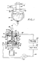
- the present invention is embodied in an apparatus 10 for continuously preparing rapidly cooled metal particles from a molten source metal by quenching into a quench liquid.
- This basic apparatus is readily incorporated into automated devices for melting pieces of source metal, preparing the metal particles, and packaging the metal particles.
- the apparatus 10 for preparing metal particles from a molten source metal by quenching into a quench liquid includes a generally cylindrical housing 12 having a provision for mounting to a support structure, and a cylindrical quench chamber 13 in which the particles are solidified.
- the quench chamber 13 is mounted for rotation about its cylindrical axis and includes an upper flange 14 and a lower flange 16 extending inwardly from the opposed ends of a wall 18, thereby defining a liquid retention volume 20.
- liquid is retained against the inside surface of the wall 18 of the housing 12, and within the liquid retention volume 20, under the action of centrifugal force.
- a spinner disk 22 is mounted within the housing 12 on a spinner disk axle 24, whose axis coincides with the cylindrical axis of the quench chamber 13.
- the quench chamber 13 and the spinner disk 22 can be rotated by a motor 26 acting through a coupling 28.
- An upper surface 30 of the spinner disk 22 is not flat or dished inwardly, as in conventional spinner disks, but instead is of convex generally conical form, its tip 32 being coincident with the axis of the spinner disk axle 24.
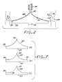
- a conical portion 35 of the upper surface 30 may extend to an outer periphery 33 of the disk 22, as illustrated in FIGURES 1, 2, and 7a.
- the conical portion 35 may extend only part way from the tip 32 to the periphery 33, so that the upper surface 30 is shaped as a central conical portion 35 surrounded by an annular flat portion 37 extending to the periphery.
- the upper surface may be raised slightly adjacent the periphery 33, to form a dished portion 39 adjacent the periphery 33.
- liquid metal flows from a source metal supply tube 34 onto the upper surface 30 of the spinner disk 22 and thence outwardly in a manner to be described.
- the quench liquid is provided to the quench chamber 13 by a supply means, preferably a quench liquid supply tube 36 which delivers quench liquid to the lower end of the interior of the housing 12 and into the liquid retention volume 20.
- Quench liquid is removed from the upper end of the housing 12 by a removing means, preferably a quench liquid removal tube 38, thereby producing a continuous flow of quench liquid through the liquid retention volume 20, from the lower end of the quench chamber 13 toward the upper end and thence out of the housing 12.
- the quench liquid and any metal particles contained therein pass from the quench chamber 13 to an external recirculation system 40.
- the recirculation system 40 includes a pump 42 for externally pumping liquid from the removal tube 38 back to the supply tube 36 and thence around the recirculation system 40.
- a particle separator 43 is included in the recirculation system 40 to remove the solidified particles from the liquid.
- the particle separator 43 may be a filter, a magnetic device if the metal particles are magnetic, a cyclone, or other appropriate separation means. If the quench liquid is volatile, such as a liquified gas or water, the particles can be separated by evaporating the quench liquid.
- a temperature trim unit 44 which, during extended continuous operation of the apparatus 10, removes heat from the quench liquid to maintain a relatively constant temperature of the quench liquid within the apparatus 10.
- the housing 12 includes a stationary upper end cap 46, a stationary lower end cap 48, and the rotatable quench chamber 13.
- the upper end cap 46, lower end cap 48, and quench chamber 13 are all cylindrical in shape, of the same cylindrical diameter, and located on a common cylindrical axis.
- the upper end cap 46 is mounted in an upper mounting 52, which supports and holds stationary the upper end cap 46.
- the lower end cap 48 is mounted in a lower mounting 54 which supports and holds stationary the lower end cap 48.
- the mountings 52 and 54 include appropriate passageways therethrough to accommodate various feedthroughs, as will be described.
- each cap 46 and 48 has a cap end flange 56 remote from the quench chamber 13, for strengthening and attachment purposes.
- Each end cap 46 and 48 also includes an internal annular rib 58 projecting inwardly from the inner wall of the cap. The annular rib 58 strengthens the cap, and additionally provides a support and attachment surface for a quench chamber bearing support means, preferably a pair of bearings 60.
- Each bearing 60 is preferably of the ball bearing type, with a bearing race 62 having an outer diameter dimensioned so that the race 62 fits within the inner diameter of the respective end cap 46 or 48.
- the race 62 faces inwardly toward the rotatable quench chamber 13.
- a plurality of ball bearings 64 roll within the race 62, and contact and support the rotatable quench chamber 13 portion of the housing 62, through contact with the outer surface of the upper and lower flanges 14 and 16.
- the present invention contemplates that the spinner disk 22 and the quench chamber 13 may rotate independently, or in the preferred embodiment, that the spinner disk 22 and the quench chamber 13 are connected by a spider 66 which is welded to the spinner disk axle 24 and the inner wall of the quench chamber 13.
- the spider 66 is a flat plate having a series of openings 68 therethrough. The outer extent of the openings 68 allows quench liquid to pass through the holes to flow upwardly from the quench liquid supply tube 36 toward the quench liquid removal tube 38.
- the one motor 26 drives both the spinner disk 22 and the quench chamber 13 in the same rotational direction and at the same rotational rate.
- Liquid source metal is supplied to the interior of the appartus 10 through the source metal supply tube 34, which is preferably a steel tube having a ceramic lining 70.
- the supply tube 34 is conveniently positioned to discharge liquid metal vertically downwardly onto the center of the protruding tip 34 of the spinner disk 22, so that the metal flow divides and flows along the upper surface 30.
- the source metal may be supplied to the supply tube 34 by any convenient source, but a preferred approach is illustrated in FIGURE 1.
- a ceramic crucible 72 is charged with the source metal.
- the source metal is heated in the crucible 72 by an induction coil 74 which is wrapped around the crucible 72.
- the crucible 72 is airtight, and its contents are sealed from contact with the atmosphere by a pair of valves, including an upper valve 76 and a lower valve 78, the space between the valves 76 and 78 defining a lock 80.
- Molten metal is forced out of the crucible 72 and into the supply tube 34 by gas pressure introduced to the space above the metal through a pressure line 82.
- Additional metal to be melted may be added into the crucible 72 without discontinuing operations by maintaining the gas pressure from the pressure line 82, and adding metal through the lock 80.
- the upper valve 76 is opened, metal is added to the lock 80, the upper valve 76 is closed, the lock 80 is pressurized by lock pressure line 84 to the same pressure as within the crucible 72, and then the lower valve 78 is opened to admit the metal pieces to the crucible 72.
- the rate of flow of liquid metal in the supply tube 34 may be regulated by a liquid metal valve 86 in the tube.
- FIGURE 2 illustrates the preferred flow pattern of liquid source metal from the supply tube 34 over the surface of the spinner disk 22 and into the liquid lying within the liquid retention volume 20.
- Liquid metal flowing out of the supply tube 34 is deposited upon the rotating apex of the tip 32 of the upper surface 30 of the spinner disk 22.
- the metal flow then divides to flow downwardly and outwardly over the upper surface 30 as a laminar flow 88.
- This laminar flow 88 is highly preferable to the premature breaking up of the metal mass into droplets 102 before reaching the periphery 33 of the spinner disk 22, since droplets cool much more rapidly by conduction or radiation than does a laminar flow.
- Maintaining a smooth, laminar flow 88 over the upper surface 30 of the spinner disk 22 is important in obtaining the greater quenching rates possible with the present apparatus. It is desirable that the droplets 102 be formed shortly before impacting into the quench liquid, since the cooling rate of the droplet in the quench liquid is much greater than in air or vacuum. It is also expected that the liquid metal will cool more rapidly as a droplet than as a laminar stream, due to the greater surface area per unit volume of the particles. The present apparatus therefore strives to delay the breakup of the laminar flow 88 into droplets until the liquid metal approaches the periphery 33 of the spinner disk 22.
- the various designs for the spinner disk 22 illustrated in FIGURES 2 and 7 achieve such a delayed formation of droplets 102, since the tip 32 serves to divide the liquid metal flowing from the supply tube 34 into a smooth laminar flow 88.
- the laminar flow 88 continues as the liquid metal stream flows outwardly, and the velocity of the liquid metal is turned through 90° from vertically downward to outward, in the view of FIGURE 2. It is not necessary that the formation of droplets 102 from the laminar flow 88 be accomplished precisely at the outer periphery 33, but instead the point of droplet formation can be adjusted by varying the precise shape of the upper surface 30.
- a more spherical particle may be obtained at the expense of a slightly lower cooling rate by using a compound surface such as illustrated in FIGURE 7b, wherein the droplets are formed closer to the radial center of the spinner disk 22, as compared with FIGURE 7a.
- a compound surface such as illustrated in FIGURE 7b, wherein the droplets are formed closer to the radial center of the spinner disk 22, as compared with FIGURE 7a.
- the spinner disk is provided as a flat plate or a dished cup.
- the downward flow of metal from the supply tube becomes turbulent upon striking the upper surface of the spinner disk, so that droplet formation is initiated very quickly.
- the droplets thus formed also reside on the spinner disk for a greater period of time before being spun outwardly into the quench liquid, since they have no radial velocity component immediately upon striking the surface of the flat spinner disk.
- the liquid metal supplied from the supply tube 34 should preferably have a temperature of about 100°C to about 150°C above the liquidus of the alloy.
- the lowest viscosity alloys present the most difficult conditions for rapid solidification.
- the preferred inner diameter of the supply tube 34 is about 1.5 to about 2.5 millimeters, and the differential pressure in the supply tube 34 as compared with the ambient environment preferably varies from about 6894.8 to about 34473.8 N/m2 (about 1 to about 5 psi), most preferably in the range from about 6894.8 to about 13789.5 N/m2 (about 1 to about 2 psi).
- a smooth laminar flow of about 0.45 liters per minute is obtained at a nozzle-to-tip distance of 1.5 millimeters and a 13789.5 N/m2 (2 psi) pressure differential.
- the droplets 102 After leaving the spinner disk 22, the droplets 102 travel a short distance outwardly before striking the surface of the quench liquid in the liquid retention volume 20. As indicated by the upward arrow in FIGURE 2, the quench liquid flowing from the supply tube 36 to the removal tube 38 produces a vertically upward current of quench liquid, so that as the droplets 102 are solidified by their contact with the quench liquid, the droplets form solid particles 104 which are swept upwardly along with the current of the quench liquid. This current then moves the particles to the removal tube 38, for removal from the apparatus 10.
- the depth of the quench liquid in the liquid retention volume 20 should be sufficiently great that the particles 104 do not penetrate the liquid to the wall 18, to ensure that the particles 104 do not adhere to the wall 18, which would cause a disruption of the flow of quench liquid.
- a depth of the quench liquid of about 3 millimeters is usually sufficient.
- the structure of the droplets 102 may be varied by the conditions of metal flow and rotation of the spinner disk 22. Where the droplets 102 are formed upon passing the periphery 33, the time of flight from the periphery 33 to the surface of the quench liquid in the retention volume 20 is thought to be less than about 10 ⁇ 3 seconds. During this short time of flight, the surface tension forces within the droplets 102 typically do not reshape the droplets 102 into a spherical form, so that the droplets 102 are shaped as liquid platelets having two relatively large dimensions, and one relatively small dimension for rapid extraction of heat in the quench liquid. Upon solidification, this shape is retained.
- This droplet and particle shape is preferred, inasmuch as the total volume of the resulting particle is much greater than the volume of a spherical particle of the same thickness in the minimum dimension.
- the cooling rates for the platelike particles are therefore comparable to those of spherical particles, having a diameter comparable with the minimum dimension of the platelet.
- the platelike particles may also have better packing efficiency when used in later compaction processes, as where the particles are placed in a mold and hot pressed into a useful article, where the particles are rolled, or where the particles are explosively compacted.
- the configuration of the droplets 102 may be varied by changing the relative dimensions of the elements of the apparatus 10 and the operating parameters so that spheres, platelets, and other shapes may be produced as desired.
- the quench liquid in the liquid retention volume 20 may be virtually any compatable liquid material.
- Quench liquids include, for example, water, water with added ingredients that aid in the rapid quenching of particles, liquid gases such as liquid nitrogen, and liquid metals of relatively low melting points.
- Water is the presently preferred quench liquid, because it is readily available, easily handled, and does not require special insulation in the apparatus 10, but water cannot be used with some reactive metals.
- the high flow rate of quench liquid and low temperature rise offer a high degree of safety, as in the quenching of aluminum into water.
- Liquid gases and liquid metals offer special advantages which may justify the extra difficulties incurred in their use.
- the use of a liquid metal as the quench liquid flowing in the retention volume 20 is distinguished from liquid source metal introduced through the source metal supply tube 34.
- the source metal is the metal solidified into particles, while the quench liquid which cools the solidifying source metal is ordinarily a different liquid metal, having a much lower melting point.
- the apparatus 10 must be insulated due to the low and high temperatures, respectively. Where liquid gases are utilized, there must be provisions to avoid overpressurization of the interior of the quench chamber 13.
- Liquid metals offer the special advantage of providing cooling without the formation of a vapor barrier at the surface of the droplets 102 and particles 104, thereby increasing the potential cooling rate. Additionally, liquid metals have greater densities than water and liquid gases, so that the particles 104 are more completely mixed into and dispersed within the quench liquid. This more complete dispersal allows uniform flow of the mixture of particles and quench liquid into the removal tube 38.
- a presently preferred liquid quench metal is a 70:30 alloy of tin and indium.
- FIGURES 3 and 4 illustrate a particle production device 106 for producing metal particles under an inert gas atmosphere.
- particles are produced by apparatus 108 of the type described previously.
- the apparatus 108 is contained in a chamber 110 of sufficient air tightness to maintain the desired inert gas atmosphere within the chamber 110.
- Molten source metal to be processed into particles is supplied to the apparatus 108 through a supply tube 34 from a furnace 128.
- the mixture of quench liquid and particles is removed from the apparatus 108 through a removal tube 114 to a roll separator 116.
- a single device 106 may conveniently include a plurality of apparatus 108 within a single chamber 110 to achieve increased particle production.
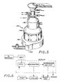
- FIGURES 5 and 6 illustrate another production embodiment of the invention, used to produce metal powder in a vacuum.
- the entire system is pumped with a vacuum pump, source metal pieces must be added through a vacuum lock, and finished particles of powder are removed through a vacuum lock.
- this vacuum production device 132 pieces of source metal are added through a lock 134 into a furnace section 136.
- Molten metal is supplied to rapid solidification apparatus (not visible) of the type previously described, contained within the solidification section 138.
- the particles are removed from the apparatus in a stream of quench liquid, and are separated in a separation section 140, for packaging. Particles are removed through a vacuum lock 142 to retain the vacuum within the production device 132.
- a sample of 1100 aluminum was melted and heated in the preferred apparatus to a temperature of about 725°C.
- the molten alloy was ejected through the supply tube under a pressure of 50 centimeters of mercury, the supply tube having a nozzle inner diameter of 1.5 millimeters and a placement 1.0 millimeter above the tip of the spinner disk.
- the disk was 4.4 centimeters in diameter and was rotated at 10,000 rpm.
- the environment was a vacuum of 74 centimeters of mercury.
- the quench liquid was water.
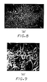
- FIGURE 8 is a scanning electron micrograph of one of the particles.
- a sample of palladium-silicon alloy containing 5.83 percent by weight of silicon was melted and heated to approximately 1100°C.
- the molten alloy was ejected through a nozzle having an inner diameter of 1.5 millimeters placed 3 millimeters above the tip of the spinner disk, under a differential pressure of 68947.6 N/m2 (10 psi).
- the spinner disk was 6.4 centimeters in diameter and rotated at 9000 rpm.
- the ambient environment was low pressure argon, and the quenchant was water. The resulting particles were in the shape of teardrops.
- FIGURE 9 A scanning electron micrograph of the particles is shown in FIGURE 9. Examples 1 and 2 were prepared using spinner disks having the configuration illustrated in FIGURE 7b.
- the present invention provides a highly versatile, economical and continuous apparatus for the preparation of rapidly solidified metal particles from source metal.
Landscapes
- Chemical & Material Sciences (AREA)
- Engineering & Computer Science (AREA)
- Nanotechnology (AREA)
- Crystallography & Structural Chemistry (AREA)
- Manufacture Of Metal Powder And Suspensions Thereof (AREA)
Claims (10)
- Installation de préparation de particules métalliques à partir d'un métal source en fusion par refroidissement rapide dans un liquide de refroidissement, l'installation comportant: une enceinte (12) contenant une chambre intérieure creuse (13) de refroidissement rapide, ladite chambre de refroidissement rapide présentant, à chacune de ses extrémités, un rebord (14,16) dirigé vers l'intérieur pour définir un volume (20) de retenue du liquide pour retenir du liquide de refroidissement rapide, ladite chambre de refroidissement rapide pouvant être entraînée en rotation autour de son axe cylindrique; un disque centrifugeur (22) situé à l'intérieur de ladite enceinte et présentant une surface supérieure (35), ledit disque centrifugeur pouvant être entraîné en rotation sur le même axe que ladite chambre de refroidissement rapide; un tube (34) d'alimentation en le métal source, positionné pour déposer le métal source en fusion substantiellement au centre de la surface supérieure dudit disque centrifugeur, sur quoi le métal source en fusion est projeté vers l'extérieur dans le liquide de refroidissement rapide; des moyens (36) pour amener le liquide de refroidissement rapide dans ledit volume de retenue du liquide de ladite enceinte à l'une de ses extrémités; et des moyens (38) pour enlever le liquide de refroidissement rapide de l'autre extrémité du volume de retenue du liquide, installation caractérisée par le fait que la surface supérieure (35) du disque centrifugeur comporte une portion qui est de forme convexe généralement conique; que le tube d'amenée (34) se termine près du sommet de la portion conique; que le diamètre de la portion conique est supérieur au diamètre intérieur du tube d'amenée, ce par quoi le métal amené par le tube d'amenée va former un écoulement laminaire sur la surface du disque centrifugeur jusqu'à ce qu'il se brise en gouttelettes à la périphérie du disque centrifugeur ou près de cette périphérie; et que les moyens (38) prévus pour enlever le liquide de refroidissement rapide sont des moyens pour enlever de façon continue, hors du volume de retenue du liquide, le liquide de refroidissement rapide et les particules solidifiées (104) qui sont mélangées avec lui.
- Installation de la revendication 1, caractérisée par le fait que le liquide de refroidissement rapide est un métal liquide, de préférence un alliage d'étain et d'indium.
- Installation de la revendication 1 ou de la revendication 2, caractérisée par le fait que ladite enceinte (12) et ledit disque centrifugeur (22) sont réunis ensemble de façon fixe, de sorte que l'un et l'autre tournent à la même vitesse.
- Installation de l'une quelconque des revendications précédentes, caractérisée par le fait que la surface supérieure (35) dudit disque centrifugeur présente une portion en cuvette (39).
- Installation de l'une quelconque des revendications 1 à 3, caractérisée par le fait que la surface supérieure (35) dudit disque centrifugeur est incurvée de façon continue.
- Installation de l'une quelconque des revendications 1 à 3, caractérisée par le fait que la surface supérieure (35) dudit disque centrifugeur inclut une portion incurvée et une portion annulaire plate.
- Installation de l'une quelconque des revendications précédentes, caractérisée par le fait que le diamètre dudit disque centrifugeur vaut entre 3 et 10 centimètres.
- Installation de l'une quelconque des revendications précédentes, caractérisée par le fait que lesdits moyens prévus pour l'enlèvement continu comportent un tube d'enlèvement (38) à extrémité ouverte, définissant le niveau liquide de refroidissement rapide dans le volume (20) de retenue du liquide lorsqu'il vient au contact de la surface du liquide de refroidissement rapide de sorte qu'une pompe (42) peut aspirer le liquide de refroidissement rapide et les particules solidifiées dans ledit tube d'enlèvement, et par le fait que lesdits moyens d'amenée comportent un tube d'amenée (36) présentant une extrémité de sortie placée immédiatement au-dessus de la surface du liquide de refroidissement rapide.
- Installation de l'une quelconque des revendications précédentes, caractérisée par le fait que des moyens (40) sont prévus pour recycler le liquide de refroidissement rapide, depuis lesdits moyens (38) prévus pour l'enlèvement continu, vers lesdits moyens (36) d'amenée, les moyens de recyclage comportant de préférence une pompe (42) pour aspirer le liquide de refroidissement rapide et les particules solidifiées dans lesdits moyens prévus pour l'enlèvement continu et pomper le liquide de refroidissement rapide vers lesdits moyens d'amenée, formant ainsi une boucle de recyclage, ainsi que des moyens (43) pour séparer les particules métalliques solidifiées d'avec le liquide de refroidissement rapide, lesdits moyens de séparation se trouvant à l'intérieur de ladite boucle de recyclage.
- Installation de l'une quelconque des revendications précédentes, comportant en outre une chambre sous vide enclosant ladite installation.
Applications Claiming Priority (2)
| Application Number | Priority Date | Filing Date | Title |
|---|---|---|---|
| US797925 | 1985-11-14 | ||
| US06/797,925 US4648820A (en) | 1985-11-14 | 1985-11-14 | Apparatus for producing rapidly quenched metal particles |
Publications (2)
| Publication Number | Publication Date |
|---|---|
| EP0226323A1 EP0226323A1 (fr) | 1987-06-24 |
| EP0226323B1 true EP0226323B1 (fr) | 1992-03-11 |
Family
ID=25172115
Family Applications (1)
| Application Number | Title | Priority Date | Filing Date |
|---|---|---|---|
| EP86308700A Expired EP0226323B1 (fr) | 1985-11-14 | 1986-11-07 | Installation de préparation de particules métalliques à partir de métal fondu |
Country Status (5)
| Country | Link |
|---|---|
| US (1) | US4648820A (fr) |
| EP (1) | EP0226323B1 (fr) |
| JP (1) | JPS62167807A (fr) |
| CA (1) | CA1279964C (fr) |
| DE (1) | DE3684258D1 (fr) |
Families Citing this family (19)
| Publication number | Priority date | Publication date | Assignee | Title |
|---|---|---|---|---|
| WO1989000470A1 (fr) * | 1987-07-20 | 1989-01-26 | Battelle Development Corporation | Procede de double desintegration de poudre |
| US4891068A (en) * | 1988-05-12 | 1990-01-02 | Teikoku Piston Ring Co., Ltd. | Additive powders for coating materials or plastics |
| CA2038449C (fr) * | 1990-03-20 | 1999-03-16 | Naotsugu Isshiki | Methode de production de poudre metallique et appareil connexe |
| FR2662102B1 (fr) * | 1990-05-16 | 1992-07-31 | Centre Nat Rech Scient | Dispositif pour la preparation d'alliages en poudre, par solidification rapide. |
| US5342557A (en) * | 1990-11-27 | 1994-08-30 | United States Surgical Corporation | Process for preparing polymer particles |
| US5143662A (en) * | 1991-02-12 | 1992-09-01 | United States Surgical Corporation | Process for preparing particles of bioabsorbable polymer |
| JP2672040B2 (ja) * | 1991-05-13 | 1997-11-05 | 株式会社クボタ | 金属粉末の製造方法およびその装置 |
| JP2672044B2 (ja) * | 1991-06-05 | 1997-11-05 | 株式会社クボタ | 金属粉末の製造方法 |
| KR0174749B1 (ko) * | 1991-06-05 | 1999-02-18 | 미노 시게가즈 | 금속분말 제조방법 및 제조장치 |
| DE19830057C1 (de) * | 1998-06-29 | 2000-03-16 | Juergen Schulze | Verfahren und Vorrichtung zum drucklosen Herstellen von Weichlotpulver |
| DE10059594A1 (de) * | 2000-11-30 | 2002-06-06 | Solarworld Ag | Verfahren und Vorrichtung zur Erzeugung globulärer Körner aus Reinst-Silizium mit Durchmessern von 50 mum bis 300 mum und ihre Verwendung |
| CN106312082A (zh) * | 2015-06-25 | 2017-01-11 | 云南锡业集团有限责任公司研究设计院 | 一种高纯锡粉的制备方法 |
| CN106077686B (zh) * | 2016-08-11 | 2018-01-02 | 重庆大学 | 一种金属颗粒制备装置和制备方法 |
| CN106001592A (zh) * | 2016-08-11 | 2016-10-12 | 重庆大学 | 一种采用常压水冷方式制备金属颗粒的装置和制备方法 |
| US11084094B1 (en) | 2017-08-08 | 2021-08-10 | Tdk Corporation | Manufacturing apparatus for metal powder and manufacturing method thereof |
| CN108941593B (zh) * | 2018-07-09 | 2020-02-14 | 华中科技大学 | 一种利用电磁力制备金属粉末的装置及方法 |
| CN109128206B (zh) * | 2018-09-25 | 2020-11-24 | 中国人民解放军陆军装甲兵学院 | 一种逐液滴离心雾化法高效制备超细球形金属粉末的装置及方法 |
| CN111804925B (zh) * | 2020-09-11 | 2020-12-11 | 陕西斯瑞新材料股份有限公司 | 一种基于VIGA工艺制备GRCop-42球形粉的方法及装置 |
| CN116920778A (zh) * | 2022-04-07 | 2023-10-24 | 深圳市恒谱生科学仪器有限公司 | 一种用于气液并流的颗粒状筛板及其制作方法 |
Family Cites Families (17)
| Publication number | Priority date | Publication date | Assignee | Title |
|---|---|---|---|---|
| US1560527A (en) * | 1921-12-08 | 1925-11-10 | Edwin M Bassler | Spraying apparatus |
| US2439772A (en) * | 1946-04-09 | 1948-04-13 | Steel Shot Producers Inc | Method and apparatus for forming solidified particles from molten material |
| US2773840A (en) * | 1952-09-19 | 1956-12-11 | Socony Mobil Oil Co Inc | Operation of hydrogel bead-forming tower |
| GB785290A (en) * | 1952-12-06 | 1957-10-23 | Moossche Eisenwerke Ag | Improvements in a process and apparatus for the production of iron granules |
| US2897539A (en) * | 1957-03-25 | 1959-08-04 | Titanium Metals Corp | Disintegrating refractory metals |
| GB1067095A (en) * | 1964-01-21 | 1967-05-03 | Snam Spa | Production of balls or spheres of refractory materials |
| US3797978A (en) * | 1970-04-15 | 1974-03-19 | Union Carbide Corp | Apparatus for producing sized ferroalloy particles |
| NL180807C (nl) * | 1975-12-26 | 1987-05-04 | Morishita Jintan Co | Inrichting voor het vervaardigen van naadloze, met materiaal gevulde capsules. |
| US4207040A (en) * | 1977-12-21 | 1980-06-10 | United Technologies Corporation | Rotary atomization means for the production of metal powder |
| JPS5940054B2 (ja) * | 1978-08-29 | 1984-09-27 | 株式会社佐藤技術研究所 | 融体から特定サイズの球形粒子を製造する方法 |
| US4375440A (en) * | 1979-06-20 | 1983-03-01 | United Technologies Corporation | Splat cooling of liquid metal droplets |
| US4284394A (en) * | 1980-09-19 | 1981-08-18 | United Technologies Corporation | Gas manifold for particle quenching |
| US4377375A (en) * | 1981-03-02 | 1983-03-22 | United Technologies Corporation | Apparatus for forming alloy powders through solid particle quenching |
| JPS5871306A (ja) * | 1981-10-26 | 1983-04-28 | Daido Steel Co Ltd | 粉末の製造方法 |
| JPS58153709A (ja) * | 1982-03-05 | 1983-09-12 | Hosokawa Funtai Kogaku Kenkyusho:Kk | 金属微粒子製造装置 |
| JPS6044364B2 (ja) * | 1983-03-14 | 1985-10-03 | 宮城工業高等専門学校長 | 金属の繊維または粉粒体の製造法 |
| US4419060A (en) * | 1983-03-14 | 1983-12-06 | Dow Corning Corporation | Apparatus for rapidly freezing molten metals and metalloids in particulate form |
-
1985
- 1985-11-14 US US06/797,925 patent/US4648820A/en not_active Expired - Fee Related
-
1986
- 1986-11-07 DE DE8686308700T patent/DE3684258D1/de not_active Expired - Fee Related
- 1986-11-07 EP EP86308700A patent/EP0226323B1/fr not_active Expired
- 1986-11-13 CA CA000522891A patent/CA1279964C/fr not_active Expired - Fee Related
- 1986-11-14 JP JP61271654A patent/JPS62167807A/ja active Pending
Also Published As
| Publication number | Publication date |
|---|---|
| CA1279964C (fr) | 1991-02-12 |
| EP0226323A1 (fr) | 1987-06-24 |
| JPS62167807A (ja) | 1987-07-24 |
| US4648820A (en) | 1987-03-10 |
| DE3684258D1 (de) | 1992-04-16 |
Similar Documents
| Publication | Publication Date | Title |
|---|---|---|
| EP0226323B1 (fr) | Installation de préparation de particules métalliques à partir de métal fondu | |
| Savage et al. | Production of rapidly solidified metals and alloys | |
| US4689074A (en) | Method and apparatus for forming ultrafine metal powders | |
| US5340377A (en) | Method and apparatus for producing powders | |
| US4435342A (en) | Methods for producing very fine particle size metal powders | |
| US5738705A (en) | Atomizer with liquid spray quenching | |
| KR890004629B1 (ko) | 용융 금속이나 준금속을 미립상으로 급속 응고시키는 방법 및 장치 | |
| US4613076A (en) | Apparatus and method for forming fine liquid metal droplets | |
| US4419060A (en) | Apparatus for rapidly freezing molten metals and metalloids in particulate form | |
| CA1160409A (fr) | Preparation de matieres granulees a prise rapide | |
| US4523621A (en) | Method for making metallic glass powder | |
| US4482375A (en) | Laser melt spin atomized metal powder and process | |
| US4824478A (en) | Method and apparatus for producing fine metal powder | |
| US5032172A (en) | Method and apparatus for making rapidly solidified particulate | |
| EP0017723B1 (fr) | Procédé et appareil pour fabriquer des poudres de métaux amorphes | |
| US4900355A (en) | Method for making high-purity metal powder by jet-cooling | |
| US4405535A (en) | Preparation of rapidly solidified particulates | |
| WO1989000471A1 (fr) | Desintegration centrifuge | |
| US6461403B1 (en) | Apparatus and method for the formation of uniform spherical particles | |
| EP0543017B1 (fr) | Procede et dispositif pour la production de poudres metalliques | |
| US4394332A (en) | Crucibleless preparation of rapidly solidified fine particulates | |
| Dixon | Atomizing molten metals—a review | |
| CA1163763A (fr) | Preparation sans recours au creuset pour fines particules rapidement solidifiees | |
| JPS61170503A (ja) | アルミニウムまたはアルミニウム基合金の微粉末の製造方法 | |
| GB2187762A (en) | Metal powder by atomization process |
Legal Events
| Date | Code | Title | Description |
|---|---|---|---|
| PUAI | Public reference made under article 153(3) epc to a published international application that has entered the european phase |
Free format text: ORIGINAL CODE: 0009012 |
|
| AK | Designated contracting states |
Kind code of ref document: A1 Designated state(s): CH DE ES FR GB LI |
|
| 17P | Request for examination filed |
Effective date: 19871214 |
|
| 17Q | First examination report despatched |
Effective date: 19890217 |
|
| GRAA | (expected) grant |
Free format text: ORIGINAL CODE: 0009210 |
|
| AK | Designated contracting states |
Kind code of ref document: B1 Designated state(s): CH DE ES FR GB LI |
|
| PG25 | Lapsed in a contracting state [announced via postgrant information from national office to epo] |
Ref country code: LI Effective date: 19920311 Ref country code: CH Effective date: 19920311 |
|
| REF | Corresponds to: |
Ref document number: 3684258 Country of ref document: DE Date of ref document: 19920416 |
|
| ET | Fr: translation filed | ||
| REG | Reference to a national code |
Ref country code: CH Ref legal event code: PL |
|
| PG25 | Lapsed in a contracting state [announced via postgrant information from national office to epo] |
Ref country code: ES Free format text: LAPSE BECAUSE OF FAILURE TO SUBMIT A TRANSLATION OF THE DESCRIPTION OR TO PAY THE FEE WITHIN THE PRESCRIBED TIME-LIMIT Effective date: 19920622 |
|
| PGFP | Annual fee paid to national office [announced via postgrant information from national office to epo] |
Ref country code: FR Payment date: 19920918 Year of fee payment: 7 |
|
| PGFP | Annual fee paid to national office [announced via postgrant information from national office to epo] |
Ref country code: GB Payment date: 19920923 Year of fee payment: 7 |
|
| PGFP | Annual fee paid to national office [announced via postgrant information from national office to epo] |
Ref country code: ES Payment date: 19921013 Year of fee payment: 7 |
|
| PGFP | Annual fee paid to national office [announced via postgrant information from national office to epo] |
Ref country code: DE Payment date: 19921231 Year of fee payment: 7 |
|
| PLBE | No opposition filed within time limit |
Free format text: ORIGINAL CODE: 0009261 |
|
| STAA | Information on the status of an ep patent application or granted ep patent |
Free format text: STATUS: NO OPPOSITION FILED WITHIN TIME LIMIT |
|
| 26N | No opposition filed | ||
| PG25 | Lapsed in a contracting state [announced via postgrant information from national office to epo] |
Ref country code: GB Effective date: 19931107 |
|
| GBPC | Gb: european patent ceased through non-payment of renewal fee |
Effective date: 19931107 |
|
| PG25 | Lapsed in a contracting state [announced via postgrant information from national office to epo] |
Ref country code: FR Effective date: 19940729 |
|
| PG25 | Lapsed in a contracting state [announced via postgrant information from national office to epo] |
Ref country code: DE Effective date: 19940802 |
|
| REG | Reference to a national code |
Ref country code: FR Ref legal event code: ST |