EP0226331A1 - Ausrichtungsvorrichtung für Dauermagnetmotoren - Google Patents
Ausrichtungsvorrichtung für Dauermagnetmotoren Download PDFInfo
- Publication number
- EP0226331A1 EP0226331A1 EP86308792A EP86308792A EP0226331A1 EP 0226331 A1 EP0226331 A1 EP 0226331A1 EP 86308792 A EP86308792 A EP 86308792A EP 86308792 A EP86308792 A EP 86308792A EP 0226331 A1 EP0226331 A1 EP 0226331A1
- Authority
- EP
- European Patent Office
- Prior art keywords
- wrapper
- permanent magnet
- end caps
- motor
- end cap
- Prior art date
- Legal status (The legal status is an assumption and is not a legal conclusion. Google has not performed a legal analysis and makes no representation as to the accuracy of the status listed.)
- Granted
Links
- 238000000034 method Methods 0.000 claims description 10
- 230000008569 process Effects 0.000 claims description 8
- 239000003302 ferromagnetic material Substances 0.000 claims description 5
- 239000000853 adhesive Substances 0.000 abstract description 5
- 230000001070 adhesive effect Effects 0.000 abstract description 5
- 230000005294 ferromagnetic effect Effects 0.000 abstract description 5
- 230000007246 mechanism Effects 0.000 abstract description 2
- 230000014759 maintenance of location Effects 0.000 abstract 1
- 238000004519 manufacturing process Methods 0.000 description 6
- 239000004020 conductor Substances 0.000 description 4
- 230000005291 magnetic effect Effects 0.000 description 4
- 230000008901 benefit Effects 0.000 description 3
- 235000019504 cigarettes Nutrition 0.000 description 3
- 229910052751 metal Inorganic materials 0.000 description 3
- 239000002184 metal Substances 0.000 description 3
- 229910000859 α-Fe Inorganic materials 0.000 description 3
- 229910000831 Steel Inorganic materials 0.000 description 2
- 238000009825 accumulation Methods 0.000 description 2
- 230000009471 action Effects 0.000 description 2
- 238000003491 array Methods 0.000 description 2
- 150000001875 compounds Chemical class 0.000 description 2
- 230000004907 flux Effects 0.000 description 2
- 239000000696 magnetic material Substances 0.000 description 2
- 230000013011 mating Effects 0.000 description 2
- AJCDFVKYMIUXCR-UHFFFAOYSA-N oxobarium;oxo(oxoferriooxy)iron Chemical compound [Ba]=O.O=[Fe]O[Fe]=O.O=[Fe]O[Fe]=O.O=[Fe]O[Fe]=O.O=[Fe]O[Fe]=O.O=[Fe]O[Fe]=O.O=[Fe]O[Fe]=O AJCDFVKYMIUXCR-UHFFFAOYSA-N 0.000 description 2
- 239000010959 steel Substances 0.000 description 2
- 229910052712 strontium Inorganic materials 0.000 description 2
- CIOAGBVUUVVLOB-UHFFFAOYSA-N strontium atom Chemical compound [Sr] CIOAGBVUUVVLOB-UHFFFAOYSA-N 0.000 description 2
- 229910000975 Carbon steel Inorganic materials 0.000 description 1
- 239000010962 carbon steel Substances 0.000 description 1
- 230000015556 catabolic process Effects 0.000 description 1
- 239000000919 ceramic Substances 0.000 description 1
- 238000010276 construction Methods 0.000 description 1
- 238000002788 crimping Methods 0.000 description 1
- 238000006731 degradation reaction Methods 0.000 description 1
- 230000001419 dependent effect Effects 0.000 description 1
- 230000000694 effects Effects 0.000 description 1
- 230000008030 elimination Effects 0.000 description 1
- 238000003379 elimination reaction Methods 0.000 description 1
- 239000000835 fiber Substances 0.000 description 1
- -1 for example Chemical class 0.000 description 1
- 238000012986 modification Methods 0.000 description 1
- 230000004048 modification Effects 0.000 description 1
- 238000000465 moulding Methods 0.000 description 1
- 230000007935 neutral effect Effects 0.000 description 1
- 238000004804 winding Methods 0.000 description 1
Images





Classifications
-
- H—ELECTRICITY
- H02—GENERATION; CONVERSION OR DISTRIBUTION OF ELECTRIC POWER
- H02K—DYNAMO-ELECTRIC MACHINES
- H02K23/00—DC commutator motors or generators having mechanical commutator; Universal AC/DC commutator motors
- H02K23/02—DC commutator motors or generators having mechanical commutator; Universal AC/DC commutator motors characterised by arrangement for exciting
- H02K23/04—DC commutator motors or generators having mechanical commutator; Universal AC/DC commutator motors characterised by arrangement for exciting having permanent magnet excitation
-
- H—ELECTRICITY
- H02—GENERATION; CONVERSION OR DISTRIBUTION OF ELECTRIC POWER
- H02K—DYNAMO-ELECTRIC MACHINES
- H02K1/00—Details of the magnetic circuit
- H02K1/06—Details of the magnetic circuit characterised by the shape, form or construction
- H02K1/12—Stationary parts of the magnetic circuit
- H02K1/17—Stator cores with permanent magnets
-
- Y—GENERAL TAGGING OF NEW TECHNOLOGICAL DEVELOPMENTS; GENERAL TAGGING OF CROSS-SECTIONAL TECHNOLOGIES SPANNING OVER SEVERAL SECTIONS OF THE IPC; TECHNICAL SUBJECTS COVERED BY FORMER USPC CROSS-REFERENCE ART COLLECTIONS [XRACs] AND DIGESTS
- Y10—TECHNICAL SUBJECTS COVERED BY FORMER USPC
- Y10T—TECHNICAL SUBJECTS COVERED BY FORMER US CLASSIFICATION
- Y10T29/00—Metal working
- Y10T29/49—Method of mechanical manufacture
- Y10T29/49002—Electrical device making
- Y10T29/49009—Dynamoelectric machine
-
- Y—GENERAL TAGGING OF NEW TECHNOLOGICAL DEVELOPMENTS; GENERAL TAGGING OF CROSS-SECTIONAL TECHNOLOGIES SPANNING OVER SEVERAL SECTIONS OF THE IPC; TECHNICAL SUBJECTS COVERED BY FORMER USPC CROSS-REFERENCE ART COLLECTIONS [XRACs] AND DIGESTS
- Y10—TECHNICAL SUBJECTS COVERED BY FORMER USPC
- Y10T—TECHNICAL SUBJECTS COVERED BY FORMER US CLASSIFICATION
- Y10T29/00—Metal working
- Y10T29/49—Method of mechanical manufacture
- Y10T29/49826—Assembling or joining
- Y10T29/49863—Assembling or joining with prestressing of part
Definitions
- This invention relates to the structure of permanent magnet motors for use in electrically-powered devices, and more particularly to a system for maintaining a predetermined orientation of the respective elements of permanent magnet motors used in such devices as appliances, power tools and the like.
- a permanent magnet motor comprising two end caps and a wrapper which extends therebetween, characterized in that said wrapper comprises a single member which extends substantially, but not completely, around the side of said permanent magnet motor.
- the wrapper engages at least one of the end caps.
- the wrapper engages both end caps and is secured thereto.
- the permanent magnet motor includes an armature rotatably mounted on the end caps and at least one, and preferably both, the end caps are provided with surfaces for spacing a magnet array from the armature.
- Means may also be provided for locating the magnet array in position with respect to the end caps.
- the magnet array may comprise, for example a single member of annular cross-section or a plurality of separate and distinct magnet segments. In the later case the magnet segments are preferably biased against said surfaces by the wrapper.
- the wrapper comprises a resilient cylindrical sleeve with a slit which extends the length thereof.
- the present invention also provides a tool, for example a portable vacuum cleaner or a power screwdriver provided with a permanent magnet motor in accordance with the invention.
- At least one of said first and second end caps has supports thereon for receiving magnet segments and said process includes the steps of:-
- the present invention comprises a permanent magnet motor for use in an electrically powered device, comprising:
- an electrically-powered device having a permanent magnet motor of the present invention is shown as a hand-held portable vacuum cleaner and is referred to generally as 10.
- This vacuum cleaner is a battery-powered appliance powered by a conventional 12-volt vehicle battery through a cigarette lighter plug conductors 12, which enter the vac at a handle 14.
- a slide button 16 actuates a switch 18, which, as shown in FIG. 2, selectively interrupts current flowing in cigarette lighter plug conductors 12.
- the switch 18 is electrically connected to a permanent magnet motor 20 of the present invention at brush contact 22, which holds a brush 24 into operative engagement with a commutator 26 mounted on an armature shaft 28.
- one of the cigarette lighter plug conductors 12 is connected to motor 20 at another brush contact 30, which holds a brush 32 into operative engagement with the commutator 26.
- switch 18 When switch 18 is actuated, the motor 20 rotates an impeller 34, which creates the desired vacuum.
- the motor 20 includes an armature 36 having end fibers 37 mounted on the armature shaft 28, which is rotatably journaled in a commutator end cap 38 and a pinion end cap 40 via end cap bearings 42, 44 mounted in respective end cap bores 46, 48.
- the armature 36 is coaxially aligned with the end cap bores 46, 48 along an armature axis 50, and one or more washers 52 are mounted on the shaft 28 adjacent the pinion end cap 40.
- a permanent magnet array 54 in this embodiment shown as being defined by two arcuate permanent magnet elements or segments 56, 58, is disposed about the armature 36 in a predetermined orientation.
- the present invention may be embodied in permanent magnet motors having "n" number of poles, it will be appreciated that the number of permanent magnet elements can vary, as can the respective orientations of the magnet arrays, without varying from the scope of the present invention.
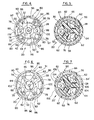
- Means operatively associated with end caps 38, 40 for maintaining the permanent magnet array 54 in its predetermined orientation are shown in detail in FIGs. 3-6.
- Such means include spring means 60 connecting the end caps 38, 40 for biasing the permanent magnet array 54 radially inwardly against cooperating radial orientation surfaces 62 formed on the end caps 38, 40.
- spring means 60 include a one-piece wrapper 64 formed of a rectangle of stamped ferromagnetic material having a high degree of perpendicularity, and further having a longitudinal split 66 defined by two opposing parallel edges 68, 70 of the rectangle.
- the wrapper 64 is formed into a tube having an inner cross-sectional dimension normally less in its free state than the cross-sectional dimension of the magnet array 54.
- the inner diameter of the wrapper 64 is normally less in its free state than the outer diameter of the magnet array 54, thereby urging inner surfaces 72, 74 of the respective magnet segments 56, 58 into engagement with the cooperating end cap radial orientation surfaces 62.
- these radial end cap surfaces 62 are formed on the end caps 38, 40 at predetermined distances from armature (and end cap bore) axis 50, thereby establishing a desired predetermined air gap 76 between the armature 36 and permanent magnet array 54.
- the biasing action of wrapper 64 maintains this orientation, while simultaneously accommodating variations in manufacturing tolerances in the magnet segments 56, 58, end caps 38, 40 and wrapper 64.
- split 66 which permits the wrapper to vary slightly in its diameter, thereby taking up the "stack-up" in tolerances radially outwardly, while still exerting biasing force radially inwardly sufficient to maintain the predetermined orientation of the magnet array 54.
- the split wrapper 64 can also coact with the end caps 38, 40 and magnet array 54 to maintain the magnet array 54 in predetermined circumferential and axial orientations relative to the end caps 38, 40 and therefor to the armature 36, as well.
- the end caps 38, 40 also include circumferential orientation surfaces 78 and axial orientation surfaces 80 which are engageable, respectively, with cooperating magnet circumferential and axial end faces 82, 84, as shown in particular in FIG. 3.
- the end cap orientation surfaces 62, 78, 80 are in turn formed on respective axial protrusions 86, 88, 90 extending axially inwardly from the end caps 38, 40.
- the split wrapper 64 and end caps 38, 40 also include cooperating elements which provide means for connecting the wrapper to the end caps in circumferential and axial alignment, thereby also eliminating the need for fasteners.
- wrapper-engaging surfaces 91 formed on end caps 38, 40 engage the respective axial ends 92, 94 of the wrapper 64, the wrapper engaging surfaces lying in planes normal to the armature axis 50.
- this engagement automatically aligns the end cap bore axes (and thus the end cap bearing axes) coaxial with the armature axis 50.
- the end caps 38, 40 also include wrapper circumferential alignment surfaces 96 which cooperate with mating recesses 98 formed 180° apart in the ends 92, 94 of the split wrapper 64. This ensures, for example, that the wrapper split 66 is aligned with a neutral axis of the magnetic field to minimize electromagnetic losses.
- the commutator end cap 38 further includes means 97 for connecting the permanent magnet motor to a source of electrical energy, namely means for mounting the brush contacts 22, as shown in FIGS. 3 and 4. End cap 38 thus becomes a multi-function structure.
- wrapper crimp tabs 100 which are crimped into mating cooperating crimp recesses 102 formed in the end caps 38, 40 after the motor elements have been assembled into position.
- the preferred embodiment provides a permanent magnet motor which enhances the alignment of its respective motor elements, but which eliminates the extra costs associated with the extra clips, fasteners, adhesives, and the like, required in conventional permanent magnet motors.
- FIGS. 7-12 and 14 Additional embodiments of the present invention are shown in FIGS. 7-12 and 14.
- the permanent magnet array 54' is defined by a single permanent magnet member extending 360° about the armature.
- end cap protrusions 88 engage cooperating recesses 104 formed in the outer surface 106 of magnet array 54', as shown in phantom on the left and right portions of FIG. 7.
- FIGS. 10-12 Yet another embodiment of the motor of the present invention using a one-piece permanent magnet array is shown in FIGS. 10-12.
- the end cap protrusions include an annular ring 108 formed on end caps 110, 112 and engaging an inner surface 114 of a one-piece magnet array 54" to orient the array in predetermined relation to the armature axis 50.
- Circumferential locators 116 are formed on the ring 108 and engage cooperating recesses 118 formed in the magnet array 54". As shown in FIG. 12, split wrapper 60 cooperates with the magnet array 54" and end cap protrusions 108 and 116 to maintain the orientation of the array relative to the end caps 110, 112.
- Magnet elements defining the arrays in the embodiments shown in FIGS. 3, 7 and 10-12 can be formed, for example, of sintered barium ferrite, strontium ferrite or other suitable magnetic material, such as plastic molded magnetic compounds.
- magnet array 54'' ' is defined by a plurality of magnet segments 122 having end faces 124, 126 in which are formed respective recesses 128, 130, extending axially inwardly of the end faces.
- Protrusions 132, 134 formed on end caps 136, 138 cooperate with the respective recesses 128, 130 to establish a predetermined orientation, such as air gap 140, and split wrapper 60 cooperates with the magnet array 54''' and end cap protrusions 132, 134 to maintain the orientation.
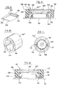
- a magnet element 122 of the configuration shown in FIG. 8 can be formed by molding the element from plastic ferrite compound including, for example, strontium ferrite or barium ferrite, or from other suitable magnetic material.
- FIG. 13 Another feature of preferred embodiments of the present invention is that it eliminates the requirement present in conventional "can" motors for separate hardware to connect the motor to a housing member of an electrically-powered device. This condition is schematically shown in FIG. 13, in which a housing mounting bracket 142 is connected to a motor can 144 by fasteners 146.
- FIG. 14 An electrical device utilizing an embodiment of the permanent magnet motor which obviates this requirement is shown in FIG. 14 as a cordless drill/driver and is referred to generally as 148.
- the drill/driver 148 includes a permanent magnet motor 150 similar to that of the preceding embodiments of the present invention.
- the motor 150 is drivingly connected to an output member, such as a gear in a gear cluster (not shown) which is operatively associated with a housing member, such as a gear case 152, which in turn is connected to the drill/driver housing 154 by fasteners 156.
- the motor is electrically connected to batteries (not shown) contained in a handle 158 via switch 160 and brushes 162 (The various conductors having been omitted from FIG. 14 for clarity.).
- the motor 150 also includes an armature 164 journaled between two end caps 166, 168, a permanent magnet array 170 engaging the end caps, and spring means 172 for maintaining the end caps and magnet array in a predetermined orientation relative to the armature.
- the spring means 172 includes a split wrapper as shown in the previously-described embodiments of the present invention, and the permanent magnet array 170 is defined by "n" number of magnet elements, also similar to those previously described.
- end cap 166 supports brushes 162, similar to the structure shown in FIG. 4. Accordingly, the end cap 166 is a unitary structure which includes first means for connecting the permanent magnet motor 150 to a source of electrical energy, similar to the brush contact mounting means 97 shown in FIGS. 3 and 4.
- End cap 168 includes structural features 170 formed integrally therewith and extending axially outwardly into nesting engagement with gear case 152. Accordingly, the end cap 168 can be a unitary structure combining motor element orientation features (as at 174) with second connection means for connecting the permanent magnet motor 150 to a housing member (as at 170), thus obviating the need for the bracket 142 and fasteners 146 shown in FIG. 13.
- first and second connection means could optionally be formed integrally with the same end cap, depending upon factors including, but not limited to, the shape and location of switches, batteries, housing members, and drive train.
- FIGURE 15 illustrates yet another problem overcome.
- the process of forming a rectangular strip of ferromagnetic material into a cylindrical open-ended wrapper generates a certain amount of axial misalignment at the junctions of two parallel edges of the rectangle, as shown in an exaggerated fashion at 176. Then, when the edges are subsequently connected in a conventional fashion, as by a dovetail joint 178, the axial misalignment 176 is frozen into place, skewing end caps 180, 182, and thereby misaligning their respective end cap bore axes 184, 186 relative to each other and to an armature axis 188. Consequently the end cap bearings 190, 192 are degraded relatively quickly by the armature (not shown), resulting in reduced motor life.
- One solution provided by the present invention first involves the step of forming the wrapper as a rectangle of sheet or strip ferromagnetic material.
- the rectangle is formed by stamping it from a sheet or strip of about 0.040" to 0.090" thick carbon steel, the hardness of the steel being selected by taking into consideration such factors as the desired spring qualities and the thickness of metal.
- One of the attributes of such a ferromagnetic wrapper is that it also provides a magnetic return path for the magnetic flux. Accordingly, inasmuch as this is dependent upon the cross-sectional area of the wrapper, the thickness and width of the rectangle should be selected so that the resultant cross-sectional area matches the desired flux flow.
- FIG. 16 shows such a strip of steel 194 from which a rectangle 196 has been stamped.
- one of the advantages (in addition to reduced cost) in forming the wrapper in this fashion is that such features as recesses 66 and crimp tabs 100 can be formed simultaneously with the rectangle 196.
- another advantage is that the rectangle 196 can be stamped using a punch and die set to hold the perpendicularity of respective intersecting rectangle edges to a high degree of accuracy.
- FIGS. 17 and 18 This automatically forces the axial ends of a cylinder formed from such a rectangle to lie in a plane which is equally accurately perpendicular to the cylinder axis.
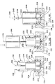
- This concept together with the split wrapper concept, provides a method for automatically aligning the two axial end cap bore axes. This is shown in FIGS. 17 and 18, in which first and second end caps 198, 200 define respective end cap bore axes 202, 204.
- One end 206 of cylinder or wrapper 208 defining a longitudinal split 210 is placed against the first end cap 198. (It should be noted at this point that the wrapper-engaging surfaces of the end caps used in the preferred magnet motor of the present invention should also lie in respective planes normal to the end cap bore axes.) As shown in FIG.
- a small axial misalignment 212 may exist.
- the edges of the wrapper defining the split 210 are not fixed together, as in the conventional joint 178 shown in FIG. 15, the misalignment 212 is not frozen, and the freedom of axial movement created by the split wrapper concept yields the following effect: when, as shown in FIG.
- the second end cap 200 is then placed against the other end 214 of the wrapper 208, and subsequently is moved towards the first end cap 198 until the axial misalignment 212 is eliminated, or until the respective wrapper axial ends 206, 214 are made flush with the end cap wrapper-engaging surfaces, the end cap bore axes 202, 204 will automatically have been coaxially aligned. This will also result in the automatic coaxial alignment of the end cap bore axes 202, 204 with the armature axis 216.
- any end cap bearings are assembled in such bores so that the bearing bore axes are coincident with the end cap bore axes 202, 204.
- a suitable holding fixture 218 supports a first end cap subassembly 220, which includes a commutator end cap 222 similar to that of the above-described embodiments of the present invention.
- the end cap 222 has magnet-engaging surfaces 224 and wrapper-engaging surface 226, and defines a commutator end cap bore 228.
- the first end cap subassembly 220 further includes a commutator bearing 230 pressed into bore 228, and an armature subassembly 232 having an armature shaft 234 journaled for rotation in bearing 230 along an armature axis 236.
- a permanent magnet array 240 having a predetermined cross-sectional dimension or outer diameter and defined by magnet segments 242, 244 is located against the cooperating end cap surfaces 224 (similar to one or more protrusions 86, 88, 90 in FIG. 3) in a predetermined orientation relative to end cap subassembly 220.
- the split wrapper 246 is then placed around the magnet array 240 and against end cap surfaces 226, and is allowed to contract to urge the magnet array 240 against end cap surfaces 224 to maintain the predetermined orientation.
- the resultant structure is shown in FIG. 19C.
- one or more washers 248 are added as needed to the armature shaft 234 to reduce armature shaft end play.
- a second end cap subassembly 250 including a pinion end cap 252 and a pinion end cap bearing pressed in a pinion end cap bore (not shown) is journaled on the armature shaft 234 adjacent the split wrapper 246 and magnet array 240.
- the second end cap subassembly 250 is then moved towards the first end cap subassembly 220 so that the wrapper 246 expands sufficiently to engage a cooperating surface 254 formed on pinion end cap 252, while still maintaining the predetermined orientation noted above.
- the wrapper is connected to the first and second end cap subassemblies, for example, by crimping, as was discussed with respect to the crimp tabs 100 shown in FIG. 3. Then such motor elements as the permanent magnet segments 242, 244 are magnetized, as by using a suitable magnetizing ring 256.
Landscapes
- Engineering & Computer Science (AREA)
- Power Engineering (AREA)
- Permanent Field Magnets Of Synchronous Machinery (AREA)
- Dc Machiner (AREA)
Applications Claiming Priority (2)
| Application Number | Priority Date | Filing Date | Title |
|---|---|---|---|
| US06/796,928 US4682066A (en) | 1985-11-12 | 1985-11-12 | Alignment system for permanent magnet motors |
| US796928 | 1985-11-12 |
Publications (2)
| Publication Number | Publication Date |
|---|---|
| EP0226331A1 true EP0226331A1 (de) | 1987-06-24 |
| EP0226331B1 EP0226331B1 (de) | 1990-03-28 |
Family
ID=25169416
Family Applications (1)
| Application Number | Title | Priority Date | Filing Date |
|---|---|---|---|
| EP86308792A Expired - Lifetime EP0226331B1 (de) | 1985-11-12 | 1986-11-12 | Ausrichtungsvorrichtung für Dauermagnetmotoren |
Country Status (3)
| Country | Link |
|---|---|
| US (1) | US4682066A (de) |
| EP (1) | EP0226331B1 (de) |
| DE (1) | DE3669964D1 (de) |
Families Citing this family (31)
| Publication number | Priority date | Publication date | Assignee | Title |
|---|---|---|---|---|
| US4793054A (en) * | 1985-11-12 | 1988-12-27 | Black & Decker Inc. | Alignment system for permanent magnet motors |
| US4873461A (en) * | 1988-05-13 | 1989-10-10 | Stryker Corporation | Electric motor sterilizable surgical power tool |
| US5144735A (en) * | 1988-06-08 | 1992-09-08 | General Electric Company | Apparatus for assembling a permanent magnet rotor |
| US5040286A (en) * | 1988-06-08 | 1991-08-20 | General Electric Company | Method for making permanent magnet rotor |
| US5237737A (en) * | 1988-06-08 | 1993-08-24 | General Electric Company | Method of making a permanent magnet rotor |
| US5563463A (en) * | 1988-06-08 | 1996-10-08 | General Electric Company | Permanent magnet rotor |
| US5345669A (en) * | 1988-06-08 | 1994-09-13 | General Electric Company | Method of making a permanent magnet rotor |
| US6348752B1 (en) * | 1992-04-06 | 2002-02-19 | General Electric Company | Integral motor and control |
| US5881448A (en) * | 1992-04-06 | 1999-03-16 | General Electric Company | Method for making permanent magnet rotor |
| JP2548233Y2 (ja) * | 1992-12-24 | 1997-09-17 | マブチモーター株式会社 | 小型モータ |
| US5861694A (en) * | 1996-06-28 | 1999-01-19 | Ryobi North America Inc. | Field retaining mechanism for a permanent magnet D.C. motor |
| US6452300B1 (en) * | 1998-12-30 | 2002-09-17 | General Electric Company | Laminated stator yokes |
| US6060799A (en) * | 1999-03-31 | 2000-05-09 | Webster Plastics | Magnet carrier for motor housing |
| US6700269B2 (en) | 2000-05-10 | 2004-03-02 | Asmo Co., Ltd. | Direct current motor yoke housing having groove-like reduced thickness portions |
| US20050174010A1 (en) * | 2000-07-31 | 2005-08-11 | Porter Eugene B. | Motor brush holder and alignment assembly |
| US6903475B2 (en) * | 2001-02-23 | 2005-06-07 | Black & Decker Inc. | Stator assembly with an overmolding that secures magnets to a flux ring and the flux ring to a stator housing |
| MXPA05006227A (es) * | 2002-12-13 | 2005-08-19 | Black & Decker Inc | Un ensamble de estator con un sobremoldeo que asegura los magnetos a un anillo de flujo y el anillo de flujo a un alojamiento del estator. |
| JP2005328601A (ja) * | 2004-05-13 | 2005-11-24 | Minebea Co Ltd | 電動シャッター又は電動ブラインド用チューブモータ |
| FI117459B (fi) * | 2004-05-31 | 2006-10-13 | Abb Oy | Menetelmä ja asennusväline sähkökoneen asentamiseksi |
| US20060238054A1 (en) * | 2005-04-26 | 2006-10-26 | Bison Gear & Engineering Corp. | Magnet retainer clip for permanent magnet electric motors |
| KR20070066089A (ko) * | 2005-12-21 | 2007-06-27 | 주식회사 대우일렉트로닉스 | 영구자석 및 로터 코어 고정용 고정판이 구비된 영구자석형직류전동기 |
| USD580725S1 (en) | 2006-01-06 | 2008-11-18 | Milwaukee Electric Tool Corporation | Power tool, such as a drill |
| US7847457B2 (en) * | 2007-05-09 | 2010-12-07 | Federal-Mogul World Wide, Inc | BLDC motor assembly |
| US8278803B2 (en) * | 2009-08-14 | 2012-10-02 | Lin Engineering | Motor end cap positioning element for maintaining rotor-stator concentricity |
| EP2580850B1 (de) | 2010-06-14 | 2021-11-10 | Black & Decker, Inc. | Steuereinheit für einen bürstenlosen motor in einem stromwerkzeug |
| US8283841B2 (en) | 2010-06-23 | 2012-10-09 | Lin Engineering | Motor end cap with interference fit |
| US11431224B2 (en) * | 2017-02-15 | 2022-08-30 | Black & Decker Inc. | Power and home tools |
| DE102018103990A1 (de) * | 2018-02-22 | 2019-08-22 | Nidec Corporation | Rotoreinheit für einen Elektromotor |
| US12059775B2 (en) | 2019-12-19 | 2024-08-13 | Black & Decker Inc. | Power tool with compact motor assembly |
| US11509193B2 (en) | 2019-12-19 | 2022-11-22 | Black & Decker Inc. | Power tool with compact motor assembly |
| US11705778B2 (en) | 2019-12-19 | 2023-07-18 | Black & Decker Inc. | Power tool with compact motor assembly |
Citations (4)
| Publication number | Priority date | Publication date | Assignee | Title |
|---|---|---|---|---|
| US2513226A (en) * | 1945-07-11 | 1950-06-27 | Redmond Company Inc | Field structure for rotating electrical equipement |
| GB1492691A (en) * | 1975-01-15 | 1977-11-23 | Pikaz Inzenyrsky Podnik | Stator for an electric machine |
| FR2404328A1 (fr) * | 1977-09-27 | 1979-04-20 | Peugeot Aciers Et Outillage | Moteur electrique de faible puissance |
| DE3135217A1 (de) * | 1981-09-05 | 1983-04-07 | Standard Elektrik Lorenz Ag, 7000 Stuttgart | Gleichstromkleinmotor |
Family Cites Families (18)
| Publication number | Priority date | Publication date | Assignee | Title |
|---|---|---|---|---|
| GB180771A (en) * | 1921-03-07 | 1922-06-07 | Charles Frederi Dufaux | Improvements relating to magneto-electric machines |
| US2878802A (en) * | 1957-08-29 | 1959-03-24 | Allan L Kuch Jr | Rubber band gun |
| US3023332A (en) * | 1959-07-20 | 1962-02-27 | Oster Mfg Co John | Electric motor construction |
| US3165654A (en) * | 1960-02-17 | 1965-01-12 | Mabuchi Takaichi | Miniature electric motors |
| US3234417A (en) * | 1961-11-24 | 1966-02-08 | Sperry Rand Corp | Low voltage d.c. motor |
| US3401281A (en) * | 1966-03-18 | 1968-09-10 | Gen Electric | Electric motor with permanent magnet stator poles and method of making |
| DE1538731A1 (de) * | 1966-06-28 | 1969-05-14 | Max Baermann | Elektrische Kleinmaschine |
| US3422295A (en) * | 1966-09-01 | 1969-01-14 | Gen Electric | Permanent magnet stator with split casing and method of making |
| US3445693A (en) * | 1967-05-26 | 1969-05-20 | Trw Inc | Dc motor with p-m stator,split housing,and brush assembly |
| US3489937A (en) * | 1967-12-18 | 1970-01-13 | Gen Electric | Motor construction |
| DE2264771A1 (de) * | 1972-07-25 | 1975-01-23 | Bosch Gmbh Robert | Topffoermiges gehaeuse, insbesondere gehaeuse von elektrischen kleinmotoren |
| US3875436A (en) * | 1973-07-16 | 1975-04-01 | Scott & Fetzer Co | Double insulated vacuum cleaner motor housing |
| US4071794A (en) * | 1975-11-10 | 1978-01-31 | General Motors Corporation | DC motor with permanent magnet retaining structure |
| DE2550640C2 (de) * | 1975-11-11 | 1985-11-21 | Interelectric Ag, Sachseln | Stator für eine elektrische Maschine |
| US4074159A (en) * | 1976-04-16 | 1978-02-14 | Robison Russell O | Dynamo-electric machine |
| US4335323A (en) * | 1980-01-17 | 1982-06-15 | Ambac Industries, Incorporated | Stamped sheet metal frame for dynamoelectric machine |
| US4505031A (en) * | 1982-09-28 | 1985-03-19 | Universal Electric Company | Method of assembling an electric motor |
| US4467231A (en) * | 1982-10-20 | 1984-08-21 | Polymotor Italiana S.P.A. | Permanent-magnet d.c. electric motor with resilient stator yoke |
-
1985
- 1985-11-12 US US06/796,928 patent/US4682066A/en not_active Expired - Lifetime
-
1986
- 1986-11-12 EP EP86308792A patent/EP0226331B1/de not_active Expired - Lifetime
- 1986-11-12 DE DE8686308792T patent/DE3669964D1/de not_active Expired - Fee Related
Patent Citations (4)
| Publication number | Priority date | Publication date | Assignee | Title |
|---|---|---|---|---|
| US2513226A (en) * | 1945-07-11 | 1950-06-27 | Redmond Company Inc | Field structure for rotating electrical equipement |
| GB1492691A (en) * | 1975-01-15 | 1977-11-23 | Pikaz Inzenyrsky Podnik | Stator for an electric machine |
| FR2404328A1 (fr) * | 1977-09-27 | 1979-04-20 | Peugeot Aciers Et Outillage | Moteur electrique de faible puissance |
| DE3135217A1 (de) * | 1981-09-05 | 1983-04-07 | Standard Elektrik Lorenz Ag, 7000 Stuttgart | Gleichstromkleinmotor |
Also Published As
| Publication number | Publication date |
|---|---|
| US4682066A (en) | 1987-07-21 |
| DE3669964D1 (de) | 1990-05-03 |
| EP0226331B1 (de) | 1990-03-28 |
Similar Documents
| Publication | Publication Date | Title |
|---|---|---|
| EP0226331B1 (de) | Ausrichtungsvorrichtung für Dauermagnetmotoren | |
| US4793054A (en) | Alignment system for permanent magnet motors | |
| JPH083152Y2 (ja) | モータのマグネット保持構造 | |
| US6580193B2 (en) | Rotary electric machine and manufacturing method therefor | |
| US4088914A (en) | Electric motor | |
| US3967148A (en) | Brush holder assembly | |
| JPH05284717A (ja) | ステッパモータ | |
| US4626178A (en) | Fuel supply pump | |
| US6747382B2 (en) | Motor | |
| US3390289A (en) | Miniature electric motor assembly | |
| US4152614A (en) | Miniature electric motors and method for manufacturing rotors for the same | |
| US20030030347A1 (en) | Motor housing having simplified cover plate and brush base | |
| KR20040010185A (ko) | 영구 자석형 회전 전기 기기 | |
| US12046950B2 (en) | Brushless motor and handheld power tool using the same | |
| US5523634A (en) | Stepping motor | |
| US5162684A (en) | Field magnet for miniature motors | |
| CN202034837U (zh) | 磁铁保持器及具有该保持器的永久磁铁式电动机 | |
| CN109936238B (zh) | 电刷装置、具有电刷装置的电动马达以及电刷装置的制造方法 | |
| JPH1155881A (ja) | 永久磁石の取付方法 | |
| JPH0640735B2 (ja) | 固定シャフトを備えたモーター | |
| JPH06245452A (ja) | Dcモータのマグネット用バックヨークおよびその製造方法 | |
| US3312845A (en) | Brush holder | |
| JP4108437B2 (ja) | 電磁クラッチ | |
| JP2001041263A (ja) | 電磁クラッチおよびその組付方法 | |
| CN219779943U (zh) | 一种无刷电机及电动工具 |
Legal Events
| Date | Code | Title | Description |
|---|---|---|---|
| PUAI | Public reference made under article 153(3) epc to a published international application that has entered the european phase |
Free format text: ORIGINAL CODE: 0009012 |
|
| AK | Designated contracting states |
Kind code of ref document: A1 Designated state(s): CH DE FR GB IT LI |
|
| 17P | Request for examination filed |
Effective date: 19870522 |
|
| 17Q | First examination report despatched |
Effective date: 19890220 |
|
| ITF | It: translation for a ep patent filed | ||
| GRAA | (expected) grant |
Free format text: ORIGINAL CODE: 0009210 |
|
| AK | Designated contracting states |
Kind code of ref document: B1 Designated state(s): CH DE FR GB IT LI |
|
| REF | Corresponds to: |
Ref document number: 3669964 Country of ref document: DE Date of ref document: 19900503 |
|
| ET | Fr: translation filed | ||
| PLBE | No opposition filed within time limit |
Free format text: ORIGINAL CODE: 0009261 |
|
| STAA | Information on the status of an ep patent application or granted ep patent |
Free format text: STATUS: NO OPPOSITION FILED WITHIN TIME LIMIT |
|
| 26N | No opposition filed | ||
| ITTA | It: last paid annual fee | ||
| PGFP | Annual fee paid to national office [announced via postgrant information from national office to epo] |
Ref country code: GB Payment date: 20011018 Year of fee payment: 16 Ref country code: FR Payment date: 20011018 Year of fee payment: 16 Ref country code: DE Payment date: 20011018 Year of fee payment: 16 |
|
| PGFP | Annual fee paid to national office [announced via postgrant information from national office to epo] |
Ref country code: CH Payment date: 20011022 Year of fee payment: 16 |
|
| REG | Reference to a national code |
Ref country code: GB Ref legal event code: IF02 |
|
| PG25 | Lapsed in a contracting state [announced via postgrant information from national office to epo] |
Ref country code: GB Free format text: LAPSE BECAUSE OF NON-PAYMENT OF DUE FEES Effective date: 20021112 |
|
| PG25 | Lapsed in a contracting state [announced via postgrant information from national office to epo] |
Ref country code: LI Free format text: LAPSE BECAUSE OF NON-PAYMENT OF DUE FEES Effective date: 20021130 Ref country code: CH Free format text: LAPSE BECAUSE OF NON-PAYMENT OF DUE FEES Effective date: 20021130 |
|
| PG25 | Lapsed in a contracting state [announced via postgrant information from national office to epo] |
Ref country code: DE Free format text: LAPSE BECAUSE OF NON-PAYMENT OF DUE FEES Effective date: 20030603 |
|
| GBPC | Gb: european patent ceased through non-payment of renewal fee | ||
| REG | Reference to a national code |
Ref country code: CH Ref legal event code: PL |
|
| PG25 | Lapsed in a contracting state [announced via postgrant information from national office to epo] |
Ref country code: FR Free format text: LAPSE BECAUSE OF NON-PAYMENT OF DUE FEES Effective date: 20030731 |
|
| REG | Reference to a national code |
Ref country code: FR Ref legal event code: ST |
|
| PG25 | Lapsed in a contracting state [announced via postgrant information from national office to epo] |
Ref country code: IT Free format text: LAPSE BECAUSE OF NON-PAYMENT OF DUE FEES;WARNING: LAPSES OF ITALIAN PATENTS WITH EFFECTIVE DATE BEFORE 2007 MAY HAVE OCCURRED AT ANY TIME BEFORE 2007. THE CORRECT EFFECTIVE DATE MAY BE DIFFERENT FROM THE ONE RECORDED. Effective date: 20051112 |