EP0226376A2 - Handhabung thermoplastischer Bahnen während ihrer Heizung - Google Patents
Handhabung thermoplastischer Bahnen während ihrer Heizung Download PDFInfo
- Publication number
- EP0226376A2 EP0226376A2 EP86309351A EP86309351A EP0226376A2 EP 0226376 A2 EP0226376 A2 EP 0226376A2 EP 86309351 A EP86309351 A EP 86309351A EP 86309351 A EP86309351 A EP 86309351A EP 0226376 A2 EP0226376 A2 EP 0226376A2
- Authority
- EP
- European Patent Office
- Prior art keywords
- web
- contacting surface
- movement
- heating
- tubes
- Prior art date
- Legal status (The legal status is an assumption and is not a legal conclusion. Google has not performed a legal analysis and makes no representation as to the accuracy of the status listed.)
- Withdrawn
Links
Images


Classifications
-
- B—PERFORMING OPERATIONS; TRANSPORTING
- B65—CONVEYING; PACKING; STORING; HANDLING THIN OR FILAMENTARY MATERIAL
- B65H—HANDLING THIN OR FILAMENTARY MATERIAL, e.g. SHEETS, WEBS, CABLES
- B65H27/00—Special constructions, e.g. surface features, of feed or guide rollers for webs
-
- B—PERFORMING OPERATIONS; TRANSPORTING
- B29—WORKING OF PLASTICS; WORKING OF SUBSTANCES IN A PLASTIC STATE IN GENERAL
- B29B—PREPARATION OR PRETREATMENT OF THE MATERIAL TO BE SHAPED; MAKING GRANULES OR PREFORMS; RECOVERY OF PLASTICS OR OTHER CONSTITUENTS OF WASTE MATERIAL CONTAINING PLASTICS
- B29B13/00—Conditioning or physical treatment of the material to be shaped
- B29B13/02—Conditioning or physical treatment of the material to be shaped by heating
- B29B13/023—Half-products, e.g. films, plates
-
- B—PERFORMING OPERATIONS; TRANSPORTING
- B32—LAYERED PRODUCTS
- B32B—LAYERED PRODUCTS, i.e. PRODUCTS BUILT-UP OF STRATA OF FLAT OR NON-FLAT, e.g. CELLULAR OR HONEYCOMB, FORM
- B32B38/00—Ancillary operations in connection with laminating processes
- B32B38/0036—Heat treatment
-
- B—PERFORMING OPERATIONS; TRANSPORTING
- B29—WORKING OF PLASTICS; WORKING OF SUBSTANCES IN A PLASTIC STATE IN GENERAL
- B29C—SHAPING OR JOINING OF PLASTICS; SHAPING OF MATERIAL IN A PLASTIC STATE, NOT OTHERWISE PROVIDED FOR; AFTER-TREATMENT OF THE SHAPED PRODUCTS, e.g. REPAIRING
- B29C59/00—Surface shaping of articles, e.g. embossing; Apparatus therefor
- B29C59/02—Surface shaping of articles, e.g. embossing; Apparatus therefor by mechanical means, e.g. pressing
- B29C59/04—Surface shaping of articles, e.g. embossing; Apparatus therefor by mechanical means, e.g. pressing using rollers or endless belts
-
- B—PERFORMING OPERATIONS; TRANSPORTING
- B29—WORKING OF PLASTICS; WORKING OF SUBSTANCES IN A PLASTIC STATE IN GENERAL
- B29K—INDEXING SCHEME ASSOCIATED WITH SUBCLASSES B29B, B29C OR B29D, RELATING TO MOULDING MATERIALS OR TO MATERIALS FOR MOULDS, REINFORCEMENTS, FILLERS OR PREFORMED PARTS, e.g. INSERTS
- B29K2027/00—Use of polyvinylhalogenides or derivatives thereof as moulding material
- B29K2027/06—PVC, i.e. polyvinylchloride
-
- B—PERFORMING OPERATIONS; TRANSPORTING
- B65—CONVEYING; PACKING; STORING; HANDLING THIN OR FILAMENTARY MATERIAL
- B65H—HANDLING THIN OR FILAMENTARY MATERIAL, e.g. SHEETS, WEBS, CABLES
- B65H2404/00—Parts for transporting or guiding the handled material
- B65H2404/10—Rollers
- B65H2404/11—Details of cross-section or profile
- B65H2404/111—Details of cross-section or profile shape
- B65H2404/1116—Polygonal cross-section
-
- B—PERFORMING OPERATIONS; TRANSPORTING
- B65—CONVEYING; PACKING; STORING; HANDLING THIN OR FILAMENTARY MATERIAL
- B65H—HANDLING THIN OR FILAMENTARY MATERIAL, e.g. SHEETS, WEBS, CABLES
- B65H2404/00—Parts for transporting or guiding the handled material
- B65H2404/10—Rollers
- B65H2404/11—Details of cross-section or profile
- B65H2404/111—Details of cross-section or profile shape
- B65H2404/1118—Details of cross-section or profile shape with at least a relief portion on the periphery
-
- B—PERFORMING OPERATIONS; TRANSPORTING
- B65—CONVEYING; PACKING; STORING; HANDLING THIN OR FILAMENTARY MATERIAL
- B65H—HANDLING THIN OR FILAMENTARY MATERIAL, e.g. SHEETS, WEBS, CABLES
- B65H2404/00—Parts for transporting or guiding the handled material
- B65H2404/10—Rollers
- B65H2404/15—Roller assembly, particular roller arrangement
- B65H2404/154—Rollers conveyor
-
- B—PERFORMING OPERATIONS; TRANSPORTING
- B65—CONVEYING; PACKING; STORING; HANDLING THIN OR FILAMENTARY MATERIAL
- B65H—HANDLING THIN OR FILAMENTARY MATERIAL, e.g. SHEETS, WEBS, CABLES
- B65H2404/00—Parts for transporting or guiding the handled material
- B65H2404/10—Rollers
- B65H2404/18—Rollers composed of several layers
- B65H2404/181—Rollers composed of several layers with cavities or projections at least at one layer
Definitions
- THIS INVENTION relates to a method of handling thermoplastic webs during heating thereof and to apparatus for use in such method.
- thermoplastic webs In the processing of thermoplastic webs it is often necessary to heat the web.
- the webs are individually heated so as to render their surfaces tacky prior to the webs passing together through a laminator nip where they are pressed together.
- Another example is an embosser, where the web to be embossed is heated prior to passing through the embosser nip.
- the conventional method of heating a web prior to the web entering a lamination or embosser nip is to pass the web partly around a rotary heating drum.
- the web is heated by heat transferred from the drum to the web through conduction.
- Thermoplastic webs tend to stick to hot surfaces, and they expand when heated.
- the combination of these two effects often causes the web to wrinkle and in places lift away from the drum surface. Those parts of the web which have lifted away from the drum surface receive less heat than those which remain in contact with the drum surface. This wrinkling, and the resulting uneven heating of the web, detrimentally affects the quality of the laminated or embossed end product.
- the heating drum needs to be large to provide a sufficiently large area over which heat transfer to the web can take place. This makes it necessary that there be a certain minimum distance between the point where the web leaves the heating drum and the lamination or embosser nip. To prevent the web from cooling down unduly while travelling this distance, radiant heaters are provided to further heat the web between the heating drum and the lamination or embosser nip. Some cooling nevertheless takes place as, in the existing arrangements where there is no physical contact with the web between where it leaves the heating drum and where it enters the lamination or embosser nip, it has not been possible to position the heaters as close to the lamination or embosser nip as is desired. It is therefore necessary to heat the web to a temperature higher than that required for lamination or embossing to take place, with obvious disadvantages.
- a method of handling a thermoplastic web during heating thereof comprises supporting or guiding the web by means of a cooled contacting surface which contacts the web, with the web moving slidably over the contacting surface, the area of contact between the web and the contacting surface being substantially less than the area of web being heated, and the contacting surface being maintained at a temperature which is below that at which the web will commence to stick to the surface.
- the contacting surface may consist of a series of surface strips which are spaced apart in the direction of movement of the web and each extend in a direction which intersects the direction of movement of the web.
- the surface strips may, on each opposite side of the web, extend at an angle of less than 90° to the direction of forward movement of the web.
- Each surface strip may be formed by a tube having a coolant medium flowing therethrough.
- the surface strips may be formed by the crests of a plurality of ridges on a cooled plate.
- apparatus for heating a moving thermoplastic web comprising: heating means for heating the web; support means for supporting or guiding the web while being heated by the heating means, the support means being arranged to support or guide the web by a contacting surface of the support means slidably contacting the web such that the area of the contacting surface is substantially less than the area of the web being heated; and cooling means for cooling the contacting surface.
- the contacting surface may consist of a series of surface strips which are spaced apart in the direction of movement of the web and each extend in a direction which intersects the direction of movement of the web.
- the surface strips may, on each opposite side of the web, extend at an angle of less then 90° to the direction of movement of the web.
- the support means may comprise a series of tubes which are spaced apart in the direction of movement of the web, the cooling means comprising means for causing a coolant medium to flow through the tubes.
- Each surface strip may be formed by the crest of an external ridge extending along a respective tube.
- the ridge may be formed by a length of wire secured to the outside of the respective tube.
- the tubes may be of polygonal cross-section, in which event each surface strip may be formed by one of the corners of a respective tube.
- the support means may comprise a plate, in which event each surface strip may be formed by the crest of a ridge protruding from a surface of the plate.
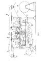
- reference numeral 10 generally indicates a laminator for producing a 3-ply PVC laminate.
- Three PVC webs 12.1, 12.2, and 12.3 are fed to the laminator from supply rolls, only one of which is shown at 14.
- the webs pass separately through a heater 16 where they are heated to the requisite temperature, and from there they are fed together into a laminator nip 18.
- a three-ply laminate 20 emerges from the laminator nip, passes around a series of cooling rollers 22, and is then wound up on an end product roll 24.
- the centre web 12.1 could, instead of being a PVC web, be a synthetic fibre scrim.
- the heater 16 is illustrated in more detail in Figure 2. It comprises, on each opposite side of the laminator, a pair of cheek plates 26, and a number of electrical bar heaters mounted between the cheek plates so as to extend transversely from one cheek plate to the opposite cheek plate. There is a first series of bar heaters 28.1 for heating opposite sides of the centre web 12.1, and a second series of bar heaters 28.2 for heating the upper surface of each of the two outer webs 12.2 and 12.3.
- the centre web 12.1 moves vertically downwards, and therefore needs no guidance or support while being heated.
- the outer webs 12.2, 12.3 cannot also move vertically downwardly while being heated and need some form of support and guidance.
- This is provided in accordance with the invention by a series of cooled, thin-walled, tubes 30.
- the tubes 30 extend across the width of the laminator and are spaced apart along the direction of movement of the respective webs 12.2, 12.3.
- the tubes 30 are mounted on the framework of the laminator by means of laterally spaced, vertically extending plates (not shown) having a gently curved upper edge.
- Each of the tubes 30, with the exception of the last tube in each series, has a cross-section as shown in Figure 3.
- the last tube in each series has a cross-section as shown in Figure 4.
- the tube 30 shown there is round in cross section and has a length of small diameter wire 32 silver soldered thereon, the wire extending along the length of the tube.
- the tubes 30 will be thin-walled stainless steel tubes having an outside diameter of 20mm, with the wire 32 silver soldered thereto having a diameter of about 2mm.
- the spacing between adjacent tubes 30 (centre line to centre line) will be in the order of 50mm.
- the web 12.2, 12.3 is supported on the tubes 30 via the wires 32. In view of the small diameter of the wire 32, the area of contact between the web 12.2, 12.3 and the wire is relatively small.
- the webs 12.2, 12.3 pass at great speed across the tubes 30. In so doing, radiant heat from the bar heaters 28.2 heat up the webs to the desired temperature for lamination to take place.
- the optimum temperature for lamination is in the order of 157 to 165°C. Cooling water is, however, circulated through the tubes 30 so as to maintain their outside surfaces at a temperature of about 80 to 90°C which is sufficiently low for the webs not to stick to them.
- the wires 32 on which the webs rest have a relatively small diameter, the arc of contact between them and the web is relatively small - virtually line contact - so that relatively little heat is lost through conduction from the web to the cooling water.
- heat reflectors 34 may be provided behind them. Furthermore, heat reflectors (not shown) may be provided behind the cooled tubes 30, so as to minimise the loss of heat radiated through the webs 12.2, 12.3.
- the source of heat should rapidly be removed from the webs 12.1, 12.2, 12.3.
- the cheek plates 26 are pivotal at 36, rams 38 being provided to pivot each assembly of cheek plates 26 and heater bars 28.1, 28.2 away from the webs.
- Heaters are available which cool down sufficiently rapidly after the electric power to them is switched off that it is not necessary to move them away from the webs in the event of an emergency stop. Should it, however, happen that the webs 12.1, 12.2, 12.3 melt or catch fire, the molten material of the webs will collect on the tubes 30. As the tubes are cooled, the material will not stick to them and can readily be removed by wiping. Any of the material which drops through the spaces between adjacent tubes 30 will fall on parts of the apparatus which are relatively cool and can likewise readily be removed by wiping.
- Figure 5 shows an alternative form of cooling tube 30.1.
- the tube 30.1 is square in cross section and arranged such that the web 12.3 rests on one of the corners thereof. It will be appreciated that the corner will not be sharp but instead will be slightly rounded, having a small radius of curvature.
- the support means 40 for use in the apparatus 10 instead of the tubes 30.
- the support means 40 comprises a front plate 42 and, spaced behind it, a backing plate 44.
- the backing plate is provided with a series of transversely extending baffle plates 46 which protrude into the space 48 between the two plates and form this space into a tortuous flow duct for coolant medium.
- the baffle plates 46 do not quite touch the front plate 42, so as to avoid distortion of the front plate.
- the external surface of the front plate 42 is machined to form a series of ridges 50.1 and 50.2.
- the ridges 50.1 extend, on each opposite side of the plate 42, in a direction which is at an angle A less than 90° to the direction B of movement of the web 12.2, 12.3 over the plate. Towards the centre of the plate, the ridges 50.1 become parabolic in shape.
- the ridge 50.2 extends along the trailing edge of the plate, i.e. the edge nearest the laminator nip 18, from one side of the plate to the other.
- the webs 12.2, 12.3 When the support means 40 is used, the webs 12.2, 12.3 will be supported on the crests of the ridges 50.1, 50.2 which will be cooled by the coolant medium circulating through the space 48.
- the effect of the ridges 50.1 which extend at an acute angle A to the direction of movement B of the web, will be to maintain the web slightly in lateral tension, thereby avoiding wrinkling of the web.
Landscapes
- Physics & Mathematics (AREA)
- Thermal Sciences (AREA)
- Engineering & Computer Science (AREA)
- Mechanical Engineering (AREA)
- Processing And Handling Of Plastics And Other Materials For Molding In General (AREA)
- Shaping Of Tube Ends By Bending Or Straightening (AREA)
- Lining Or Joining Of Plastics Or The Like (AREA)
- Laminated Bodies (AREA)
Applications Claiming Priority (2)
| Application Number | Priority Date | Filing Date | Title |
|---|---|---|---|
| ZA859442 | 1985-12-10 | ||
| ZA859442 | 1985-12-10 |
Publications (2)
| Publication Number | Publication Date |
|---|---|
| EP0226376A2 true EP0226376A2 (de) | 1987-06-24 |
| EP0226376A3 EP0226376A3 (de) | 1988-09-21 |
Family
ID=25578183
Family Applications (1)
| Application Number | Title | Priority Date | Filing Date |
|---|---|---|---|
| EP86309351A Withdrawn EP0226376A3 (de) | 1985-12-10 | 1986-12-01 | Handhabung thermoplastischer Bahnen während ihrer Heizung |
Country Status (3)
| Country | Link |
|---|---|
| EP (1) | EP0226376A3 (de) |
| JP (1) | JPS62146613A (de) |
| ZW (1) | ZW24086A1 (de) |
Cited By (2)
| Publication number | Priority date | Publication date | Assignee | Title |
|---|---|---|---|---|
| EP0469694A3 (de) * | 1990-07-29 | 1992-03-11 | Gencorp Inc. | Vorrichtung und Verfahren zum Prägen |
| US5641374A (en) * | 1995-03-16 | 1997-06-24 | Minnesota Mining And Manufacturing Company | Apparatus and method for preventing defects during the lamination of materials |
Family Cites Families (4)
| Publication number | Priority date | Publication date | Assignee | Title |
|---|---|---|---|---|
| DE1936808A1 (de) * | 1968-07-19 | 1970-01-29 | Scragg & Sons | Praegewalze fuer thermoplastische Folien und Verfahren zur Herstellung ihrer reliefartigen Praegeflaeche |
| US4105491A (en) * | 1975-02-21 | 1978-08-08 | Mobil Oil Corporation | Process and apparatus for the manufacture of embossed film laminations |
| DD122795A1 (de) * | 1975-11-11 | 1976-11-05 | ||
| US4352771A (en) * | 1981-04-16 | 1982-10-05 | Variform Plastics, Inc. | Method and apparatus for creating random shadow patterns in formed vinyl sheet article |
-
1986
- 1986-12-01 EP EP86309351A patent/EP0226376A3/de not_active Withdrawn
- 1986-12-08 JP JP61290628A patent/JPS62146613A/ja active Pending
- 1986-12-08 ZW ZW240/86A patent/ZW24086A1/xx unknown
Cited By (2)
| Publication number | Priority date | Publication date | Assignee | Title |
|---|---|---|---|---|
| EP0469694A3 (de) * | 1990-07-29 | 1992-03-11 | Gencorp Inc. | Vorrichtung und Verfahren zum Prägen |
| US5641374A (en) * | 1995-03-16 | 1997-06-24 | Minnesota Mining And Manufacturing Company | Apparatus and method for preventing defects during the lamination of materials |
Also Published As
| Publication number | Publication date |
|---|---|
| JPS62146613A (ja) | 1987-06-30 |
| EP0226376A3 (de) | 1988-09-21 |
| ZW24086A1 (en) | 1988-07-13 |
Similar Documents
| Publication | Publication Date | Title |
|---|---|---|
| EP2418332B1 (de) | Vorrichtung zur herstellung eines reflektierenden wärmeisolators | |
| EP0048503B1 (de) | Hitzeschild für band- oder knüppelförmiges Material | |
| US4658716A (en) | Infrared heating calender roll controller | |
| US5571368A (en) | Laminating machine with improved heating and cooling | |
| GB2162872A (en) | Regulating web caliper | |
| DE4208219C1 (de) | ||
| SE437349B (sv) | Formband for en press for utovning av ytpressning | |
| EP0226376A2 (de) | Handhabung thermoplastischer Bahnen während ihrer Heizung | |
| EP0104811B1 (de) | Verfahren und Vorrichtung zum Prägen und Kontrollieren der Spannung einer kontinuierlichen, bewegten Folie | |
| US4188253A (en) | Machine for the fabrication of plasticboard | |
| CA2034258A1 (en) | Electromagnetic induction heater | |
| US4124415A (en) | Process for heating metal strips, in particular non-ferrous metal strips | |
| EP0519609B1 (de) | Verfahren zur Herstellung einer transparenten Platte, eine so hergestellte Platte und Walze für ihr Kalandrieren | |
| JPH1178090A5 (de) | ||
| CN214137804U (zh) | 一种布条双面热转印机 | |
| CN222985508U (zh) | 极片加热装置及极片辊压系统 | |
| US5245148A (en) | Apparatus for and method of heating thick metal slabs | |
| WO1991012135A1 (en) | Method of bonding metal sheet material to a core or base sheet material and also an apparatus for carrying out said method | |
| CN217387186U (zh) | 一种焊带处理装置及串焊机 | |
| KR100363275B1 (ko) | 형강재의 주면에 전사필림 용착장치 | |
| JP2006256055A (ja) | 樹脂シートの製造方法 | |
| JP3497339B2 (ja) | 極薄金属帯の加熱方法 | |
| US5942180A (en) | Method and apparatus for heating fiber reinforced thermoplastics by means of contact heating means | |
| EP4715881A1 (de) | Trocknungskammervorrichtung zur verhinderung der mäanderung einer elektrodenfolie für eine sekundärbatterie | |
| JPS61279518A (ja) | 強化樹脂板連続製造装置 |
Legal Events
| Date | Code | Title | Description |
|---|---|---|---|
| PUAI | Public reference made under article 153(3) epc to a published international application that has entered the european phase |
Free format text: ORIGINAL CODE: 0009012 |
|
| AK | Designated contracting states |
Kind code of ref document: A2 Designated state(s): AT CH DE FR GB IT LI NL SE |
|
| PUAL | Search report despatched |
Free format text: ORIGINAL CODE: 0009013 |
|
| AK | Designated contracting states |
Kind code of ref document: A3 Designated state(s): AT CH DE FR GB IT LI NL SE |
|
| STAA | Information on the status of an ep patent application or granted ep patent |
Free format text: STATUS: THE APPLICATION IS DEEMED TO BE WITHDRAWN |
|
| 18D | Application deemed to be withdrawn |
Effective date: 19890322 |
|
| RIN1 | Information on inventor provided before grant (corrected) |
Inventor name: LE MAITRE, RICHARD BRUCE CARLYLE |