EP0226431B1 - Hohlfasermodul für Trennungsverfahren - Google Patents
Hohlfasermodul für Trennungsverfahren Download PDFInfo
- Publication number
- EP0226431B1 EP0226431B1 EP86309566A EP86309566A EP0226431B1 EP 0226431 B1 EP0226431 B1 EP 0226431B1 EP 86309566 A EP86309566 A EP 86309566A EP 86309566 A EP86309566 A EP 86309566A EP 0226431 B1 EP0226431 B1 EP 0226431B1
- Authority
- EP
- European Patent Office
- Prior art keywords
- bundle
- hollow fiber
- hollow
- port
- module according
- Prior art date
- Legal status (The legal status is an assumption and is not a legal conclusion. Google has not performed a legal analysis and makes no representation as to the accuracy of the status listed.)
- Expired - Lifetime
Links
Images
Classifications
-
- B—PERFORMING OPERATIONS; TRANSPORTING
- B01—PHYSICAL OR CHEMICAL PROCESSES OR APPARATUS IN GENERAL
- B01D—SEPARATION
- B01D53/00—Separation of gases or vapours; Recovering vapours of volatile solvents from gases; Chemical or biological purification of waste gases, e.g. engine exhaust gases, smoke, fumes, flue gases, aerosols
- B01D53/22—Separation of gases or vapours; Recovering vapours of volatile solvents from gases; Chemical or biological purification of waste gases, e.g. engine exhaust gases, smoke, fumes, flue gases, aerosols by diffusion
-
- B—PERFORMING OPERATIONS; TRANSPORTING
- B01—PHYSICAL OR CHEMICAL PROCESSES OR APPARATUS IN GENERAL
- B01D—SEPARATION
- B01D63/00—Apparatus in general for separation processes using semi-permeable membranes
- B01D63/02—Hollow fibre modules
- B01D63/024—Hollow fibre modules with a single potted end
-
- B—PERFORMING OPERATIONS; TRANSPORTING
- B01—PHYSICAL OR CHEMICAL PROCESSES OR APPARATUS IN GENERAL
- B01D—SEPARATION
- B01D63/00—Apparatus in general for separation processes using semi-permeable membranes
- B01D63/02—Hollow fibre modules
- B01D63/025—Bobbin units
-
- B—PERFORMING OPERATIONS; TRANSPORTING
- B01—PHYSICAL OR CHEMICAL PROCESSES OR APPARATUS IN GENERAL
- B01D—SEPARATION
- B01D2313/00—Details relating to membrane modules or apparatus
- B01D2313/23—Specific membrane protectors, e.g. sleeves or screens
-
- B—PERFORMING OPERATIONS; TRANSPORTING
- B01—PHYSICAL OR CHEMICAL PROCESSES OR APPARATUS IN GENERAL
- B01D—SEPARATION
- B01D2319/00—Membrane assemblies within one housing
- B01D2319/04—Elements in parallel
Definitions
- This invention pertains to hollow fiber separatory module devices, and more particularly to a separatory module which comprises an annular fiber bundle and in which fluid flows parallel to the central axis of the fiber array.
- membranes to effect separation of gas/gas, liquid/liquid, and liquid/solid mixtures and solutions has achieved general industrial applicability by various methods, among them being ultrafiltration, hyperfiltration reverse osmosis, dialysis.
- membrane elements associated with these processes are contained in vessels called modules, comprising a shell having various inlet and outlet ports and an assembly of membranes within said shell.
- the internal configurations are so arranged as to permit the introduction of a feed stream with or without pressure on the upstream face of the membranes, means for collecting permeate which passes through the membrane and emerges on their downstream faces, and means for keeping feed and permeate materials from commingling.
- US-A-4,207,192 discloses one form of hollow filament separatory module and method for its fabrication.
- hollow fiber membranes When hollow fiber membranes are used to separate components of a gas mixture, or solutes dissolved in liquid solutions, there are a number of methods of flowing the mixture to be separated over the membranes.
- the flowing method employed determines the manner in which the individual hollow fiber membrane units are to be organized within the pressure shell.
- One very common method of fiber arrangement involves arranging large numbers of parallel and straight fibers into a generally cylindrical cross-section comprising thousands or perhaps millions of such fibers arranged around an axially parallel center core tube.
- the core tube may be perforated or slotted and act as an inlet conduit for pressurized feed fluid.
- the fluid is pumped outward among the fibers at right angles to their axes and as it reaches the outer regions of the fiber array the fluid is collected in an annular space adjacent to the pressure shell inner wall surface.
- the same general physical arrangement of fibers might be used for flowing in the opposite direction by introducing feed in the annular space adjacent to the inner wall surface of the pressure shell and traversing radially inward toward the perforated tube lying in the center of the fiber array.
- the fiber may be wound around the center core tube in reversing helical fashion and feed introduced either into the core tube or into the perimeter of the bundle as discussed above. All of these options correspond to different forms of cross-flow feeding. That is, the flow direction or permeate in the bores of the fibers is generally at right angles to the direction of flow of the feed over their external surfaces.
- a preferable mode of feed direction flow is co-or counter-flow, parallel to the flow of permeate in the hollow fibers.
- the feed In order to achieve either of these the feed must generally flow parallel to, rather than at a right angle to, the central axis of the fiber array.
- the fibers may be organized either in straight assemblies parallel to the central axis of the array or, alternatively, wound in helical fashion around said central axis, as in the cross-flow situations.
- French Patent Serial No. 2 542 203 describes a dialyser which comprises a bundle of fibers wrapped in a sheet and mounted within an outer shell.
- the sheet facilitates the insertion of the fiber bundle into the shell and abuts the inside wall of the shell for the majority of its length.
- bypass route may be, for example, between the inner surface of the shell wall and the outermost fibers of the bundle.
- relatively loosely packed parallel arrays of fibers that there may be bypass channels among the fibers.
- One possible means to overcome the latter bypass problem is to wind the fibers into relatively tight packages by helical winds of alternating S & Z directions around a central support member, thereby creating a generally annular bundle. Such a bundle arrangement may then be inserted into a pressure containment shell, but a means must be found to occlude any space between the outer regions of the bundle and inner surface of the pressure shell wall to avoid the first bypass route noted above.
- FR-A-2 267 138 discloses the use of an impermeable casing arranged around hollow fibers in a separation apparatus, which casing is made at least partially of an elastic material or a material having an elastic memory, and may, for example, be a heat-shrunk casing. (See also US Patent No. 4,400,276).
- An object of the present invention is to provide a hollow fiber separatory module utilising axial feed fluid flow, wherein the problem of bypass flow occurring along the fiber bundle-pressure shell interface or among relatively loosely packed fibers can be overcome.
- the present invention provides a hollow fiber separatory module for separating fluids into permeate and raffinate components, comprising an annular hollow fiber bundle having first and second ends, potting material encapsulating said second bundle end, an impermeable barrier encasing the entirety of the longitudinal cylindrical surface of said bundle except for an opening located adjacent to said potting material, an end-cap sealed at the first end of the bundle to said barrier, a pressure resistant shell encasing said bundle and defining a channel between the inside surface of said shell and the external surface of said barrier, a port at said second bundle end in fluid communication with the bores of the hollow fibers for the removal of permeate component, a first port at said first bundle end in fluid communication with the external surfaces of the hollow fibers near said second bundle end via the channel, and a second port at said first bundle end in fluid communication with the external surfaces of the hollow fibers via a hollow mandrel which extends along the longitudinal axis of the bundle and passes through said end-cap, said bundle consisting of fibers helically
- the impermeable barrier material may be a wrap of an impervious film, or it may be an impervious coating material applied from a solvent that is innocuous to the membrane.
- the impervious barrier may alternatively be in the form of a shrink sleeve installed over the bundle and shrunk onto the bundle.
- the annular hollow fiber bundle is wound upon the mandrel, which comprises a hollow tube having one end extending through the end-cap, said one end having an opening therein for communication with the exterior of the module, the hollow tube also having at least one opening in a wall thereof, said opening being located interiorly of the end-cap and providing fluid communication with the fiber bundle.
- the inlet feed means may be in fluid communication with the channel, and the outlet means for the raffinate component may be in fluid communication with the fiber bundle.
- the inlet feed means may be in fluid communication with the fiber bundle and the outlet means for the raffinate component may be in fluid communication with the channel.
- feed fluid refers to a feed liquid or a feed gas.
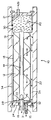
- FIG. 1 illustrates a hollow fiber separatory module 10 for separating feed fluid.
- An annular shaped hollow fiber bundle 12 is formed by winding individual fibers in helical winds about a mandrel in the form of a hollow support mandrel 14 which is preferably a hollow support rod defining an exit passage, and which has a bundle access port 16.
- Said access port may serve as the connection to the pressurized feed source, or as an exit for raffinate fluid which does not permeate the walls of the hollow filament.
- Fiber bundle 12 is encased by an impermeable barrier 18 which may be a wrap of an impervious film (for example polyvinylidene or the like) or it may be an impervious coating material applied from an innocuous solvent (for example, polysiloxane).
- the impervious barrier 18 may be a shrink sleeve installed over the bundle and shrunk onto it. In any event barrier material 18 closely adheres to the external cylindrical surface of the bundle and to end-cap 28. Barrier material 18 along with end-cap 28 encapsulates the entirety of the surface of fiber bundle 12 except for an unencapsulated circumferential surface region 19.
- potting material 20 is applied to the opposite end of fiber bundle 12 as shown. Potting material is a resinous sealant for terminating the fiber ends and for keeping feed and permeate materials from commingling. Fiber bore openings are created in an oblique plane of the potting material indicated at 21. Permeates exit from the system at 29.
- Shell 22 is designed to withstand internal fluid pressures generated by inlet of pressurized fluid feed into the separatory module. At one end shell 22 has two ports, 15 and 16.
- the double headed arrows signify alternative possible flow directions such that if port 16 is the inlet for pressurized feed, 15 is the outlet for raffinate, and vice versa.
- the feed gas on the upstream side of the fiber surface flows generally parallel to and in the same direction as the flow permeate gas in the fiber bores, normally in a co-flow mode.
- the flow path through the bundle is generally parallel but in the direction opposite to flow permeate in the fiber bores.
- “O” rings 30 provide an impermeable seal between potting material 20 and the inside surface of the pressure resistant shell.
- Other “O" rings 31, 32 seal between end-plate 24 and tube 14 and between end-plate 24 and the inside surface of pressure shell 22.
- the fluid feed to the separating module can be a feed liquid or a feed gas and, in general, it may be admitted at one end of the fiber bundle 12, the pressurized fluid being either removed from, or admitted to flow among the fibers of, the bundle only at the circumferential region 19 left unwrapped or uncoated.
- the only other access to the fibers per se of the bundle is by means of an inlet or outlet feature 16 of the support rod or mandrel 14, located at the bundle end distal to the unencased region 19.
Landscapes
- Chemical & Material Sciences (AREA)
- Chemical Kinetics & Catalysis (AREA)
- Engineering & Computer Science (AREA)
- Analytical Chemistry (AREA)
- General Chemical & Material Sciences (AREA)
- Oil, Petroleum & Natural Gas (AREA)
- Separation Using Semi-Permeable Membranes (AREA)
- Spinning Methods And Devices For Manufacturing Artificial Fibers (AREA)
- Cell Separators (AREA)
- External Artificial Organs (AREA)
Claims (10)
- Ein Hohlfaser-Trennmodul (10) für das Separieren von Fluiden in Permeat- und Raffinatkomponenten, umfassend ein ringförmiges Hohlfaserbündel (12) mit einem ersten und einem zweiten Ende, Vergußmaterial (20), mit dem das zweite Bündelende eingekapselt ist, eine impermeable Barriere (18), die die Gesamtheit der zylindrischen Längsoberfläche des Bündels umschließt mit Ausnahme einer Öffnung (19), die nahe dem Vergußmaterial angeordnet ist, eine Endkappe (28), die an dem ersten Ende des Bündels mit der Barriere versiegelt ist, eine druckfeste Schale (22), die das Bündel umschließt und einen Kanal (34) zwischen der Innenoberfläche der Schale und der Außenoberfläche der Barriere begrenzt, eine Öffnung (29) an dem zweiten Bündelende in Fluidkommunikation mit den Bohrungen der Hohlfasern für den Austrag der Permeatkomponente, eine erste Öffnung (15) an dem ersten Bündelende in Fluidkommunikation mit den Außenoberflächen der Hohlfasern nahe dem zweiten Bündelende über den Kanal (34), und eine zweite Öffnung (16) an dem ersten Bündelende in Fluidkommunikation mit den Außenoberflächen der Hohlfasern über einen Hohldorn (14), der sich längs der Längsachse des Bündels erstreckt und die Endkappe durchsetzt, wobei das Bündel (12) aus Fasern besteht, die schraubenlinienförmig um den Dorn (14) gewunden sind, dadurch gekennzeichnet, daß die impermeable Barriere (18) sich dicht an die zylindrische Längsoberfläche des Bündels anschmiegt, und daß die genannte Öffnung (19) sich in Umfangsrichtung um die zylindrische Längsoberfläche des Bündels an dem zweiten Ende des Bündels erstreckt und dieses gegenüber dem Kanal (34) exponiert derart, daß der Zustrom in oder der Raffinatstrom aus der zylindrischen Längsoberfläche an diesem zweiten Ende des Bündels gleichförmig rings um das Bündel ist.
- Ein Hohlfaser-Trennmodul nach Anspruch 1, ferner umfassend eine Dichtung (30), die zwischen dem Vergußmaterial (20) und der druckfesten Schale (22) angeordnet ist.
- Ein Hohlfaser-Trennmodul nach Anspruch 1 oder Anspruch 2, bei dem die impermeable Barriere (18) eine Schrumpfhülse ist, die auf das Hohlfaserbündel (12) aufgeschrumpft ist.
- Ein Hohlfaser-Trennmodul nach Anspruch 1 oder Anspruch 2, bei dem die impermeable Barriere (18) eine Umhüllung aus einer undurchdringlichen Folie ist.
- Ein Hohlfaser-Trennmodul nach Anspruch 4, bei dem die impermeable Barriere (18) aus Polyvinyliden zusammengesetzt ist.
- Ein Hohlfaser-Trennmodul nach Anspruch 1 oder Anspruch 2, bei dem die impermeable Barriere (18) aus Polysiloxan besteht.
- Ein Hohlfaser-Trennmodul nach einem der vorangehenden Ansprüche, bei dem der hohle Dorn (14) ein hohles Rohr umfaßt, das sich mit einem Ende durch die Endkappe (28) erstreckt, welches eine Ende eine Öffnung darin aufweist für die Kommunikation mit dem Äußeren des Moduls, welches hohle Rohr ferner mindestens eine Öffnung in einer Wandung desselben aufweist, welche Öffnung innerhalb der Endkappe (28) liegt und Fluidkommunikation mit dem Faserbündel (12) herstellt.
- Die Anwendung eines Hohlfaser-Trennmoduls nach einem der Ansprüche 1 bis 7, bei der der Zustrom an der ersten Öffnung (15) eingelassen wird und die Raffinatkomponente an der zweiten Öffnung (16) ausgetragen wird.
- Die Anwendung eines Hohlfaser-Trennmoduls nach einem der Ansprüche 1 bis 7, bei der der Zustrom an der zweiten Öffnung (16) eingelassen wird und die Raffinatkomponente an der ersten Öffnung (15) ausgetragen wird.
- Die Anwendung eines Hohlfaser-Trennmoduls nach Anspruch 8 oder 9 für das Trennen der Komponenten in einem Gas/Fluidgemisch.
Applications Claiming Priority (4)
| Application Number | Priority Date | Filing Date | Title |
|---|---|---|---|
| US80735885A | 1985-12-10 | 1985-12-10 | |
| US807358 | 1985-12-10 | ||
| US83115886A | 1986-02-19 | 1986-02-19 | |
| US831158 | 1986-02-19 |
Publications (3)
| Publication Number | Publication Date |
|---|---|
| EP0226431A2 EP0226431A2 (de) | 1987-06-24 |
| EP0226431A3 EP0226431A3 (en) | 1988-04-27 |
| EP0226431B1 true EP0226431B1 (de) | 1995-04-05 |
Family
ID=27122999
Family Applications (1)
| Application Number | Title | Priority Date | Filing Date |
|---|---|---|---|
| EP86309566A Expired - Lifetime EP0226431B1 (de) | 1985-12-10 | 1986-12-09 | Hohlfasermodul für Trennungsverfahren |
Country Status (6)
| Country | Link |
|---|---|
| EP (1) | EP0226431B1 (de) |
| JP (1) | JPH06142462A (de) |
| AT (1) | ATE120664T1 (de) |
| CA (1) | CA1319892C (de) |
| DE (1) | DE3650292T2 (de) |
| EG (1) | EG18145A (de) |
Families Citing this family (14)
| Publication number | Priority date | Publication date | Assignee | Title |
|---|---|---|---|---|
| US4961760A (en) * | 1989-02-09 | 1990-10-09 | The Dow Chemical Company | Hollow fiber membrane fluid separation device adapted for boreside feed |
| US5059374A (en) * | 1989-02-09 | 1991-10-22 | The Dow Chemical Company | Method for sealing a hollow fiber membrane module in a case |
| US4934148A (en) * | 1989-05-12 | 1990-06-19 | Union Carbide Corporation | Dry, high purity nitrogen production process and system |
| US5004482A (en) * | 1989-05-12 | 1991-04-02 | Union Carbide Corporation | Production of dry, high purity nitrogen |
| US4931070A (en) * | 1989-05-12 | 1990-06-05 | Union Carbide Corporation | Process and system for the production of dry, high purity nitrogen |
| US5026479A (en) * | 1990-02-13 | 1991-06-25 | Union Carbide Industrial Gases Technology Corporation | Fluid separation device |
| US5084073A (en) * | 1990-10-11 | 1992-01-28 | Union Carbide Industrial Gases Technology Corporation | Membrane drying process and system |
| US5226932A (en) | 1991-10-07 | 1993-07-13 | Praxair Technology, Inc. | Enhanced meambrane gas separations |
| US5205842A (en) * | 1992-02-13 | 1993-04-27 | Praxair Technology, Inc. | Two stage membrane dryer |
| CA2663724A1 (en) * | 2006-09-22 | 2008-04-03 | Porous Media Corporation | Helically wound hollow fiber membrane module with modified ends |
| WO2008123031A1 (ja) | 2007-03-28 | 2008-10-16 | Aoki Science Institute Co., Ltd. | 鋳造用油性離型剤、塗布方法及び静電塗布装置 |
| CN103826729B (zh) | 2011-09-12 | 2019-06-28 | 3M创新有限公司 | 改进的接触器、筒、组件、系统和相关方法 |
| JP6795443B2 (ja) * | 2017-03-31 | 2020-12-02 | ダイセン・メンブレン・システムズ株式会社 | 中空糸膜モジュール |
| GB201818934D0 (en) * | 2018-11-21 | 2019-01-02 | Parker Hannifin Emea Sarl | Device for separating components of a gas mixture |
Family Cites Families (7)
| Publication number | Priority date | Publication date | Assignee | Title |
|---|---|---|---|---|
| FR2267138A1 (en) * | 1974-04-09 | 1975-11-07 | Rhone Poulenc Ind | Hollow fibre bundle for fluid treatment - partic. useful for dialysis or ultrafiltration |
| JPS54110183A (en) * | 1978-02-16 | 1979-08-29 | Toyobo Co Ltd | Membrane separator |
| US4207192A (en) | 1978-09-19 | 1980-06-10 | Albany International Corp. | Hollow filament separatory module and method of fabrication |
| US4308654A (en) * | 1979-09-24 | 1982-01-05 | Monsanto Company | Methods for assembling permeators |
| US4400276A (en) | 1979-10-18 | 1983-08-23 | Monsanto Company | Apparatus having tube sheets for hollow fibers |
| US4378981A (en) * | 1981-12-21 | 1983-04-05 | Monsanto Company | Gas separation apparatus |
| IT8353037U1 (it) * | 1983-03-10 | 1984-09-10 | Sorin Biomedica Spa | Apparecchio dializzatore a fibre cave |
-
1986
- 1986-11-11 EG EG698/86A patent/EG18145A/xx active
- 1986-11-20 CA CA000523438A patent/CA1319892C/en not_active Expired - Fee Related
- 1986-12-09 EP EP86309566A patent/EP0226431B1/de not_active Expired - Lifetime
- 1986-12-09 DE DE3650292T patent/DE3650292T2/de not_active Expired - Fee Related
- 1986-12-09 AT AT86309566T patent/ATE120664T1/de not_active IP Right Cessation
-
1992
- 1992-02-19 JP JP4069790A patent/JPH06142462A/ja active Pending
Also Published As
| Publication number | Publication date |
|---|---|
| ATE120664T1 (de) | 1995-04-15 |
| EP0226431A2 (de) | 1987-06-24 |
| DE3650292T2 (de) | 1995-09-21 |
| JPH06142462A (ja) | 1994-05-24 |
| EP0226431A3 (en) | 1988-04-27 |
| DE3650292D1 (de) | 1995-05-11 |
| EG18145A (en) | 1992-08-30 |
| CA1319892C (en) | 1993-07-06 |
Similar Documents
| Publication | Publication Date | Title |
|---|---|---|
| US4865736A (en) | Hollow fiber separatory module with encased fiber bundle | |
| US5160042A (en) | Double ended hollow fiber bundle and fluids separation apparatus | |
| EP0554567B1 (de) | Gewebekartuschen mit spiralförmig gewickelten Hohlfasermembranen und Module mit strömungsableitenden Einbauten | |
| KR940004620B1 (ko) | 유공섬유 다중막 셀 및 여과기 | |
| US5837033A (en) | Hollow fiber membrane separation apparatus | |
| US6755894B2 (en) | Hollow fiber membrane gas separation cartridge and gas purification assembly | |
| US5071552A (en) | Multiple bundle fluid separation apparatus | |
| US5176725A (en) | Multiple stage countercurrent hollow fiber membrane module | |
| US5702601A (en) | Structure enhancing hollow fiber module | |
| US4715953A (en) | Hollow fiber separation device manifold | |
| CA1319892C (en) | Hollow fiber separatory module with encased fiber bundle | |
| EP0038612B1 (de) | Hohlfasermoduln | |
| US20050258091A1 (en) | Apparatus and method for separating fluids through a membrane | |
| EP0627254B1 (de) | Hohlfasermembrantrennvorrichtung mit einem Gehäuse aus einem flexiblen Material | |
| EP0228836B1 (de) | Gehäuseende mit Gewinde | |
| US5207906A (en) | Membrane separation module | |
| US5234591A (en) | Counter-current flow hollow fiber permeator | |
| WO2001066231A1 (en) | Apparatus and method for separating fluids through a membrane | |
| EP1261411B1 (de) | Vorrichtung zur trennung von fluiden durch eine membrane | |
| EP0103953B1 (de) | Trennmodul für Hohlfasermembranen | |
| JPH0229372B2 (de) | ||
| EP4168160B1 (de) | Diffusionsvorrichtung |
Legal Events
| Date | Code | Title | Description |
|---|---|---|---|
| PUAI | Public reference made under article 153(3) epc to a published international application that has entered the european phase |
Free format text: ORIGINAL CODE: 0009012 |
|
| AK | Designated contracting states |
Kind code of ref document: A2 Designated state(s): AT BE CH DE FR GB IT LI LU NL SE |
|
| PUAL | Search report despatched |
Free format text: ORIGINAL CODE: 0009013 |
|
| AK | Designated contracting states |
Kind code of ref document: A3 Designated state(s): AT BE CH DE FR GB IT LI LU NL SE |
|
| 17P | Request for examination filed |
Effective date: 19881004 |
|
| 17Q | First examination report despatched |
Effective date: 19900705 |
|
| RAP1 | Party data changed (applicant data changed or rights of an application transferred) |
Owner name: ALBANY INTERNATIONAL CORP. |
|
| GRAA | (expected) grant |
Free format text: ORIGINAL CODE: 0009210 |
|
| AK | Designated contracting states |
Kind code of ref document: B1 Designated state(s): AT BE CH DE FR GB IT LI LU NL SE |
|
| REF | Corresponds to: |
Ref document number: 120664 Country of ref document: AT Date of ref document: 19950415 Kind code of ref document: T |
|
| REF | Corresponds to: |
Ref document number: 3650292 Country of ref document: DE Date of ref document: 19950511 |
|
| ITF | It: translation for a ep patent filed | ||
| ET | Fr: translation filed | ||
| PLBE | No opposition filed within time limit |
Free format text: ORIGINAL CODE: 0009261 |
|
| STAA | Information on the status of an ep patent application or granted ep patent |
Free format text: STATUS: NO OPPOSITION FILED WITHIN TIME LIMIT |
|
| 26N | No opposition filed | ||
| PGFP | Annual fee paid to national office [announced via postgrant information from national office to epo] |
Ref country code: GB Payment date: 19971201 Year of fee payment: 12 |
|
| PGFP | Annual fee paid to national office [announced via postgrant information from national office to epo] |
Ref country code: FR Payment date: 19971209 Year of fee payment: 12 |
|
| PGFP | Annual fee paid to national office [announced via postgrant information from national office to epo] |
Ref country code: LU Payment date: 19971212 Year of fee payment: 12 Ref country code: DE Payment date: 19971212 Year of fee payment: 12 Ref country code: AT Payment date: 19971212 Year of fee payment: 12 |
|
| PGFP | Annual fee paid to national office [announced via postgrant information from national office to epo] |
Ref country code: SE Payment date: 19971218 Year of fee payment: 12 |
|
| PGFP | Annual fee paid to national office [announced via postgrant information from national office to epo] |
Ref country code: NL Payment date: 19971223 Year of fee payment: 12 |
|
| PGFP | Annual fee paid to national office [announced via postgrant information from national office to epo] |
Ref country code: CH Payment date: 19980106 Year of fee payment: 12 |
|
| PGFP | Annual fee paid to national office [announced via postgrant information from national office to epo] |
Ref country code: BE Payment date: 19980217 Year of fee payment: 12 |
|
| PG25 | Lapsed in a contracting state [announced via postgrant information from national office to epo] |
Ref country code: LU Free format text: LAPSE BECAUSE OF NON-PAYMENT OF DUE FEES Effective date: 19981209 Ref country code: GB Free format text: LAPSE BECAUSE OF NON-PAYMENT OF DUE FEES Effective date: 19981209 Ref country code: AT Free format text: LAPSE BECAUSE OF NON-PAYMENT OF DUE FEES Effective date: 19981209 |
|
| PG25 | Lapsed in a contracting state [announced via postgrant information from national office to epo] |
Ref country code: SE Free format text: LAPSE BECAUSE OF NON-PAYMENT OF DUE FEES Effective date: 19981210 |
|
| PG25 | Lapsed in a contracting state [announced via postgrant information from national office to epo] |
Ref country code: LI Free format text: LAPSE BECAUSE OF NON-PAYMENT OF DUE FEES Effective date: 19981231 Ref country code: CH Free format text: LAPSE BECAUSE OF NON-PAYMENT OF DUE FEES Effective date: 19981231 Ref country code: BE Free format text: LAPSE BECAUSE OF NON-PAYMENT OF DUE FEES Effective date: 19981231 |
|
| BERE | Be: lapsed |
Owner name: ALBANY INTERNATIONAL CORP. Effective date: 19981231 |
|
| PG25 | Lapsed in a contracting state [announced via postgrant information from national office to epo] |
Ref country code: NL Free format text: LAPSE BECAUSE OF NON-PAYMENT OF DUE FEES Effective date: 19990701 |
|
| GBPC | Gb: european patent ceased through non-payment of renewal fee |
Effective date: 19981209 |
|
| REG | Reference to a national code |
Ref country code: CH Ref legal event code: PL |
|
| PG25 | Lapsed in a contracting state [announced via postgrant information from national office to epo] |
Ref country code: FR Free format text: LAPSE BECAUSE OF NON-PAYMENT OF DUE FEES Effective date: 19990831 |
|
| NLV4 | Nl: lapsed or anulled due to non-payment of the annual fee |
Effective date: 19990701 |
|
| REG | Reference to a national code |
Ref country code: FR Ref legal event code: ST |
|
| PG25 | Lapsed in a contracting state [announced via postgrant information from national office to epo] |
Ref country code: DE Free format text: LAPSE BECAUSE OF NON-PAYMENT OF DUE FEES Effective date: 19991001 |
|
| PG25 | Lapsed in a contracting state [announced via postgrant information from national office to epo] |
Ref country code: IT Free format text: LAPSE BECAUSE OF NON-PAYMENT OF DUE FEES;WARNING: LAPSES OF ITALIAN PATENTS WITH EFFECTIVE DATE BEFORE 2007 MAY HAVE OCCURRED AT ANY TIME BEFORE 2007. THE CORRECT EFFECTIVE DATE MAY BE DIFFERENT FROM THE ONE RECORDED. Effective date: 20051209 |