EP0226497B1 - Stromabnehmerkopf für Oberleitungsbus - Google Patents
Stromabnehmerkopf für Oberleitungsbus Download PDFInfo
- Publication number
- EP0226497B1 EP0226497B1 EP86402553A EP86402553A EP0226497B1 EP 0226497 B1 EP0226497 B1 EP 0226497B1 EP 86402553 A EP86402553 A EP 86402553A EP 86402553 A EP86402553 A EP 86402553A EP 0226497 B1 EP0226497 B1 EP 0226497B1
- Authority
- EP
- European Patent Office
- Prior art keywords
- cradle
- main body
- head according
- trolley bus
- bus head
- Prior art date
- Legal status (The legal status is an assumption and is not a legal conclusion. Google has not performed a legal analysis and makes no representation as to the accuracy of the status listed.)
- Expired - Lifetime
Links
- 230000010355 oscillation Effects 0.000 claims description 10
- 238000003825 pressing Methods 0.000 claims description 3
- 230000035939 shock Effects 0.000 claims description 2
- 238000006073 displacement reaction Methods 0.000 claims 1
- 230000005540 biological transmission Effects 0.000 description 8
- 238000000465 moulding Methods 0.000 description 7
- 238000000034 method Methods 0.000 description 5
- 238000009987 spinning Methods 0.000 description 5
- 229910003460 diamond Inorganic materials 0.000 description 4
- 239000010432 diamond Substances 0.000 description 4
- 238000003754 machining Methods 0.000 description 4
- 238000012423 maintenance Methods 0.000 description 4
- 238000004519 manufacturing process Methods 0.000 description 4
- 208000031968 Cadaver Diseases 0.000 description 3
- OKTJSMMVPCPJKN-UHFFFAOYSA-N Carbon Chemical compound [C] OKTJSMMVPCPJKN-UHFFFAOYSA-N 0.000 description 3
- 229910052799 carbon Inorganic materials 0.000 description 3
- 238000000605 extraction Methods 0.000 description 3
- 238000010438 heat treatment Methods 0.000 description 3
- 239000000463 material Substances 0.000 description 3
- 230000006835 compression Effects 0.000 description 2
- 238000007906 compression Methods 0.000 description 2
- 239000000470 constituent Substances 0.000 description 2
- 238000005520 cutting process Methods 0.000 description 2
- 238000013461 design Methods 0.000 description 2
- 210000005069 ears Anatomy 0.000 description 2
- 238000005304 joining Methods 0.000 description 2
- 238000012986 modification Methods 0.000 description 2
- 230000004048 modification Effects 0.000 description 2
- 241000269800 Percidae Species 0.000 description 1
- 241000826860 Trapezium Species 0.000 description 1
- 238000004026 adhesive bonding Methods 0.000 description 1
- XAGFODPZIPBFFR-UHFFFAOYSA-N aluminium Chemical compound [Al] XAGFODPZIPBFFR-UHFFFAOYSA-N 0.000 description 1
- 229910052782 aluminium Inorganic materials 0.000 description 1
- 238000005266 casting Methods 0.000 description 1
- 238000007796 conventional method Methods 0.000 description 1
- 238000001816 cooling Methods 0.000 description 1
- 238000012937 correction Methods 0.000 description 1
- 230000006378 damage Effects 0.000 description 1
- 238000009826 distribution Methods 0.000 description 1
- 230000005489 elastic deformation Effects 0.000 description 1
- 230000003203 everyday effect Effects 0.000 description 1
- 230000002349 favourable effect Effects 0.000 description 1
- 238000009434 installation Methods 0.000 description 1
- 210000000056 organ Anatomy 0.000 description 1
- BASFCYQUMIYNBI-UHFFFAOYSA-N platinum Chemical compound [Pt] BASFCYQUMIYNBI-UHFFFAOYSA-N 0.000 description 1
- 230000000284 resting effect Effects 0.000 description 1
- 229910001220 stainless steel Inorganic materials 0.000 description 1
- 239000010935 stainless steel Substances 0.000 description 1
Images


Classifications
-
- B—PERFORMING OPERATIONS; TRANSPORTING
- B60—VEHICLES IN GENERAL
- B60L—PROPULSION OF ELECTRICALLY-PROPELLED VEHICLES; SUPPLYING ELECTRIC POWER FOR AUXILIARY EQUIPMENT OF ELECTRICALLY-PROPELLED VEHICLES; ELECTRODYNAMIC BRAKE SYSTEMS FOR VEHICLES IN GENERAL; MAGNETIC SUSPENSION OR LEVITATION FOR VEHICLES; MONITORING OPERATING VARIABLES OF ELECTRICALLY-PROPELLED VEHICLES; ELECTRIC SAFETY DEVICES FOR ELECTRICALLY-PROPELLED VEHICLES
- B60L5/00—Current collectors for power supply lines of electrically-propelled vehicles
- B60L5/04—Current collectors for power supply lines of electrically-propelled vehicles using rollers or sliding shoes in contact with trolley wire
- B60L5/08—Structure of the sliding shoes or their carrying means
- B60L5/085—Structure of the sliding shoes or their carrying means with carbon contact members
Definitions
- the present invention relates to the field of trolleybuses on similar vehicles, and more particularly a trolleybus head of the type comprising a cradle body mounted pivoting at the end of the pole, a cradle mounted on the cradle body with a link allowing an oscillation around a substantially vertical axis and a tilting around a substantially horizontal axis, said cradle receiving a wear shoe for the transmission of current to a cable carried by the pole, via a shunt connected to the cradle.
- the cradle has in its upper part a part having a groove with inclined sides, often called a friction shoe.
- a wear shoe is housed by conical wedging in the groove of this part, and a safety strip is provided to prevent any accidental extraction in reverse, the conical wedging being naturally provided in such a way that the tightening tends to be reinforced when the trolley bus is in forward gear.
- the wiper is a wearing part which must be changed very regularly, and often every day. Therefore, recessed mounting, if it is mechanically safe, involves a tedious disassembly operation: the operator must first unscrew the safety blade, then take a tool giving a shock to extract the wear shoe , and proceed again to the reverse maneuver for the installation of a new wiper.
- the wear wiper has a relatively high manufacturing cost due to its inclined face shape: it must in fact be machined from a piece cut from a plate, the machining having to be treated with care. to the tolerances for electrical contact with the relevant faces of the groove of the wiper.
- French Patent No. 2,320,204 gives an illustration of a wiper of this type, used for a head comprising a wiper mounted at each end of a pendulum.
- the electrical contact remains imperfect due to the friction between the smooth surfaces of the wear wiper and the wiper, the smoothness being made compulsory due to the sliding embedding: in reality, the contact is in fact limited. at localized points or zones, which not only influences the quality of the contact for the transmission of the current, but risks causing undesirable heating due to the concentration of the current in these few zones.
- trolleybus heads use a wear shoe which is not embedded, by providing a cradle in two parts fixed to each other by bolting.
- Swiss Patent No. 359,463 describes a trolleybus head, the cradle of which has a bolted upper part on each side of a median longitudinal plane, and thus maintaining a wear friction against a smooth support and contact face.
- German Patent No. 974,463 describes a technique similar to the previous one, with bolting in a median longitudinal plane.
- the quality of the electrical contact is improved compared to the head described in the aforementioned Swiss patent, thanks to two flat contact blades sandwiched between a support face of the cradle and the wear wiper, but the drawbacks already mentioned for the rigid support of the wear shoe by bolting remains.
- the object of the invention is to provide a trolleybus head that is more efficient than the aforementioned heads.
- the object of the invention is in particular to allow rapid and easy disassembly, without special tools, for the replacement of the wear shoe.
- the invention also aims to be able to use a wear wiper whose shape allows economical mass production, in particular by means of spinning techniques, while providing good electrical contact.
- a trolleybus head comprising a cradle body mounted pivoting at the end of the pole, a cradle mounted on the cradle body with a link allowing oscillation around a substantially vertical axis and tilting around of a substantially horizontal axis, said cradle receiving a wear shoe for the transmission of current to a cable carried by the pole, by means of a shunt connected to the cradle, characterized in that the cradle comprises a body main having a support and contact face for the lower part of the wear shoe, and a movable part lockable on the main body, said movable part being articulated on an axis carried by the main body of said cradle and having a longitudinal opening for the passage of the upper part of the wear wiper, elastically deformable means being provided for maintaining the wiper wear against the support and contact face when the movable part is locked on the main body.
- the wear wiper has in its lower part two longitudinal wings with which the movable part of the cradle cooperates to hold said wear wiper on the support face and contact, by means of elastically deformable means.
- the elastically deformable means then comprise two wavy branches, a wavy branch being housed between each longitudinal wing of the wear wiper and an associated rim provided on the movable part of the cradle in the vicinity of the longitudinal opening thereof, when said movable part is locked on the main body.
- these means preferably constitute a single element, carried by the mobile part of the cradle.
- the single element constituting the elastically deformable means advantageously has a connecting tab crossed by the hinge axis of the movable cradle part.
- This single element then has a generally rectangular shape, with a recess corresponding to the passage of the upper part of the wear shoe.
- the main body of the cradle has a support and contact face in diamond points, which was not possible. with the sliding embedding provided in the context of known techniques. Provision may be made for the main body of the cradle to have, at each end of its support and contact face, a stop ensuring the maintenance of the wear shoe in a longitudinal direction.
- connection shunt which was connected to the rear end of the wiper: in particular here, the main body of the cradle has a central connection portion receiving the end of the shunt which arrives at the cradle passing through the center of the articulation link of said cradle.
- the mobile part of the cradle is as previously articulated by an axis on the main body of said cradle, but said axis is mounted on said body with the possibility of movement in one direction substantially perpendicular to the support and contact face, said movable part having, in the vicinity of the longitudinal opening thereof, a double flange in direct contact with the upper lateral edges of the wear shoe, and that the means elastically deformable comprise a spring member acting on the articulation axis so as to exert on the movable part of the cradle a force in order to maintain the wear friction shoe on the support and contact face.
- the first variant of the trolley bus head may indeed, in certain applications, present some drawbacks, in particular when one chooses to produce the elastically deformable means in the form of a spring element comprising two wavy branches. Maintaining the wear wiper is ensured, in this particular embodiment, by the support of the two corrugated branches on an associated longitudinal wing provided at the base of said wiper, thanks to the action of a double longitudinal edge formed on the movable part of the cradle, each branch being bordered above by the cradle rim and below by the wing of the wear shoe.
- line switchgear for crossings, switches or deviations for example
- the current flow takes place through the cheeks of the movable part of the cradle, the function of which is above all a function of guiding the pickup line cable. If a spring element with wavy branches is used, this element can then be subjected to overcurrents, of the order of 500 amperes for example, which can lead to the destruction of said spring element.
- the main body of the cradle has oblong bearings receiving the ends of the hinge pin.
- the spring member is a torsion spring mounted on the main body of the cradle, and at least one branch of which bears on the articulation axis; it is also advantageous for the articulation axis to have a sharp edge on which the branch of the torsion spring bears when the movable part of the cradle is in the locked position.
- the elastically deformable means also comprise a locking clip mounted at the other end of the mobile part of the cradle; the mobile part of the cradle is then doubly floating.
- the support and contact face is essentially constituted by contact strips having a certain elasticity, and arranged on the upper face of the main body of the cradle; such lamellae ensure good contact, while allowing a correction of the tolerances for the contact face of the wear wiper, resulting from molding or spinning of a profile of charged carbon agglomerate.
- the contact strips are in the form of at least one plate arranged in a longitudinal groove of the main body of the cradle; in particular, two plates are provided, arranged on either side of a central connection portion of the main body of the cradle designed to receive the end of a shunt passing through the articulation link of the cradle.
- the invention also relates to a wear wiper intended to equip a trolleybus head thus improved, this wiper being characterized by the fact that it is constituted by an elongated body of essentially constant cross section, said section having substantially the shape of a trapezoid whose small base corresponds to a lower planar face to be applied against the support and contact face of the main body of the cradle.
- the wear wiper has two parallel facets adjacent to the upper lateral edges on which the associated edges of the movable part of the cradle bear, then two inclined faces joining the lower flat face of said wear wiper; in particular, each of the inclined faces forms an angle of approximately 30 ° with the adjacent facet.
- FIGS 1 and 2 illustrate a trolleybus head according to the invention, as mounted at the end of the trolleybus pole.
- the head 1 has a certain number of constituent organs whose arrangement allows several degrees of freedom relative to the pole.
- a pole end body 2 usually made of an aluminum molded part, mounted coaxially (by gluing or other means) on the end of an insulating tube 3 representing the end of the pole, the rest of which is not shown.
- a piece 4 usually called cradle body, which can pivot around an oblique axis 5, over a predetermined angular range (stops not shown in principle limit this pivoting to 90 ° on either side of the median position corresponding to a pole located in the vertical plane of the collection line).
- a cradle 6 On the part 4 is mounted a cradle 6 with a link allowing an oscillation around a substantially vertical axis 7, with stops not shown to limit the angular range of oscillations, said cradle 6 can also tilt around an axis substantially horizontal.
- the connection between the cradle 6 and the cradle body part 4 is not a ball joint as was frequently the case in the prior techniques, but on the contrary defines two determined articulation axes, which presents certain advantages to which we will return later.
- the articulation axes 5, 7 form between them an angle of between 15 ° and 25 ° , so as to obtain satisfactory behavior of the trolleybus head, even in the event of a tight turn.
- the cradle 6 comprises a main body 8 having a support and contact face 9 for the lower part of a wear shoe 10, which is used for the transmission of current to a cable 11 carried by the pole, by means of a shunt 12 connected to the cradle; said cradle also comprises a movable articulated part 13, lockable on the main body 8, and having a longitudinal opening for the passage of the upper part of the wear shoe 10.
- said wiper Due to an assembly of the wear wiper without embedding, said wiper can be easily produced from a profile of uniform section, this section appearing more clearly in FIG. 2, which makes it possible to have a manufacturing method economical thanks to the use of techniques such as spinning.
- the operator just has to unlock the mobile part of the cradle to manually release the wear wiper to be replaced, and instantly put in place a new wiper before locking new said movable part: these operations are therefore particularly easy for the operator, who can replace the wearing part in a very short time, and without any tools.
- the embodiment illustrated here comprises a movable part 13 of the cradle articulated on a fixed axis 14 carried by the main body 8 of said cradle; the moving part 13 has a symmetrical configuration, with a pair of ears 15 at each of its ends, one pair being provided for the articulation, while the other is provided for carrying an elastic locking tab 16 which can cooperate in position locking with a molding 17 formed for this purpose on the main body of the cradle.
- the movable part of the cradle has a longitudinal opening 18, substantially rectangular, for the passage of the upper part of the wear shoe between the two flanges of the movable part provided, in accordance with custom, for lateral guidance relative to the collection line 19, as is more clearly shown in FIG. 2.
- the wear wiper 10 thus has in its lower part two longitudinal wings 20 defining, downwards, the face of said wiper intended to be applied against the support and contact face 9, and, upwards, two faces of support 21 which receives the application force of the elastically deformable means which are arranged between these support faces, and an associated flange 22 provided on the mobile part of the cradle in the vicinity of the longitudinal opening 18.
- the elastically deformable means advantageously consist of a single element 23, the shape of which is illustrated in perspective in FIG. 3.
- This single element comprises two wavy branches 24 which are housed, in the locked position of the movable part of the cradle, between the wings longitudinal 20 of the wear wiper and the aforementioned flanges 22 of said movable part.
- the single element thus has a generally rectangular shape, with a recess 25 corresponding to the passage of the upper part of the wear shoe, and, on one side, a connecting tab 26 crossed by the articulation axis of the mobile part of the cradle (shown diagrammatically by the axis 27 in FIG.
- the wear wiper 10 is thus perfectly positioned on the support and contact face 9 of the main body of the cradle, advantageously between two stops 30, the function of which is to maintain said wiper in a longitudinal direction.
- the fact that the wear wiper 10 is simply placed on the support and contact face 9 makes it possible to produce said face in diamond points, an arrangement which could not be adopted with the old design of a sliding recess of said wiper. 'wear.
- the diamond tips are slightly encrusted in the face opposite the wear shoe, and the multiplicity of contact points obtained ensures excellent current transmission between said wear shoe and the cradle; these points also allow the tolerances to be made up for the contact face of the wear wiper, resulting from molding or spinning of a profile of charged carbon agglomerate.
- the regular distribution of these points will naturally have a favorable effect from a thermal point of view, the heating at the level of the contact being equally distributed for the whole of the wear wiper.
- the main body 8 of the cradle in fact has a central connection portion 31 for the tightening of the ends of the shunt 12 by means of screws 32, these ends thus extending between the lateral flanges 33 of the main cradle body, then in the bore of a socket 34 of the articulated connection of said cradle on the part 4.
- this sleeve 34 is surrounded by a sleeve 35, inside a guide sleeve 36 whose outer surface has, on each side, a projecting circular groove 37 received in a corresponding groove 38, formed on the associated flange 33 towards the interior the main body of the cradle.
- the friction pieces 35, 36 can naturally be produced in a single piece, for example from a material such as that marketed under the name ERTAFLUOR, which has good sliding characteristics at temperatures which may exceed 120 ° C.
- the central part of the shunt 12 will pass inside a central sleeve 39 (preferably made of stainless steel), at the level of the articulation connection with the body at the end of the pole 2.
- This sleeve 39 incorporated during the casting of the cradle body part 4, receives two external friction sleeves 40, preferably, in a material having good sliding characteristics, such as that marketed under the name ERTALON, because it It suffices here to withstand temperatures not exceeding 70 ° C.
- the end of the shunt 12 is finally connected to an electrical junction piece 41 ensuring the connection with the cable 11.
- the trolleybus head thus produced in accordance with the invention, allows rapid and easy disassembly, without special tools, for the replacement of the wear shoe, which can be carried out in a particularly economical manner, without in any way harming the electrical contact obtained.
- the cross section of the wear shoe may differ from that shown in FIG. 2, and the elastically deformable means may also have structures that are substantially different from that illustrated in FIG. 3.
- the articulation links through which the shunt passes and more particularly that of the cradle carrying the wear friction shoe, by providing, for example, lampholders with contact spring capable to transmit current: this makes it possible in particular to avoid transmission of current by the spring, when the movable part of the cradle is alone in contact with the pick-up line (case of crossings or switches).
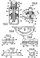
- the second variant of the trolley bus head which will now be described with reference to FIGS. 4 to 13, comprises a certain number of constituent members similar to those forming the trolley bus head which has just been described.
- the references used for these members in the following description will correspond to the references of the previous variant increased by the number 100.
- the head 101 comprises a pole tip body 102 mounted at the end of an insulating tube 103; on this pole end body 102 is articulated a cradle body 104 which can pivot about an oblique axis 105, over a predetermined angular range.
- a cradle body 104 On the piece 104 is mounted a cradle 106 with a link allowing an oscillation around a substantially vertical axis 107, said cradle 106 also being able to tilt around a substantially horizontal axis.
- the cradle 106 comprises a main body 108 having a support and contact face 109 (to which it will be returned later) for the underside of a wear shoe 110, which is used for the transmission of current to a cable 111 carried by the pole, by means of a shunt 112 connected to the cradle; said cradle also includes a mobile part 113 articulated on an axis 114 carried by the main body 108, and having a longitudinal opening for the passage of the upper part of the wear shoe 110.
- the mobile part 113 is of symmetrical configuration, with a pair of ears 115 at each of its ends, one pair being provided for articulation, while the other is provided for carrying an elastic locking tab 116 which can cooperate in the locking position with a molding 117 provided for this purpose on the main body of the cradle.
- the hinge pin 114 of the movable part of the cradle is mounted on the main body 108 with the possibility of movement in a direction substantially perpendicular to the support face and contact 109, the movable part 113 of the cradle having, in the vicinity of the longitudinal opening 118 thereof, a double flange 122 in direct contact with the upper lateral edges of the wear shoe 110;
- the elastically deformable means are provided for holding the wear shoe 110 against the support and contact face when the mobile part is locked on the main body, but these means here comprise a spring member 142 acting on the hinge pin 114 so as to exert on the movable part 113 of the cradle the desired holding force.
- each of the two lateral flanges 133 of the main body 108 thus comprises an oblong bearing 143 receiving the associated end of the hinge pin 114.
- this flange 133 is symmetrical design, to simplify manufacture and avoid any risk of assembly error: there is thus an oblong bearing 143 and a molding 117 at each end of the flange, it being understood that the oblong bearing is essential at the level of the hinge pin 114 only, and that the molding 117 is in turn essential to cooperate with the locking clip 116.
- Such an assembly gives the mobile part 113 an extremely interesting floating character, because it is this which allows direct support by the flanges 122 on the wiper 110, as is particularly visible in FIG. 5. It is easy to see that, in the event of interruption of the electrical contact with the wiper 110 when the head passes to the level of line switchgear of the type mentioned above, the cheeks of the movable part 113 ensure the direct passage of the current towards the wiper 110, without passing through an intermediate element such as the spring element with wavy branches 23 of the previous variant. The cheeks of the mobile part 113 thus perform a double function, that is to say the guiding of the collection line 119, and the electrical contact for the direct flow of current.
- FIG. 11 illustrates a possible embodiment for the torsion spring 142 mounted on the body main 108 of the cradle.
- This spring is mounted on an axis 144 passing through the lugs 145 of a plate 146 placed between the lateral flanges 133 and the upper part 109 of which constitutes the support and contact face for the wear shoe 110.
- the two branches free ends 147 of the spring 142 are pressed against the underside of the plate 146, while the branch 148 permanently exerts an application pressure directed downward on the hinge pin 114.
- the spring 142 tends thus always to move the axis 114 towards the lower part of the oblong bearing 143.
- a hinge pin 114 of square section has been illustrated here: this axis thus has a sharp edge 149 on which the branch 148 of the torsion spring bears.
- the locking member of the mobile part which is here a clip 116, has a sufficient capacity for elastic deformation to also fulfill, like the torsion spring 142 but to a lesser extent, an elastic holding function of the wear wiper 110 on the support and contact face 109 when the movable part is locked on the main body.
- the mobile part of the cradle is then doubly floating.
- the support and contact face 109 is advantageously constituted by contact strips having a certain elasticity, and disposed on the upper face of the main body of the cradle.
- two plates 150 are arranged in a longitudinal groove 151 of the plate 146 of the main body of the cradle; these two plates are arranged on either side of a central connection portion 131 of the main body of the cradle designed to receive the end of the shunt 112 passing through the articulation links of the cradle.
- These contact strips give better results than the diamond tips provided on the face of the head contact support in accordance with the preceding variant: their flexibility ensures both good contact and allows the tolerances for the face to be made up. contact of the wear wiper, which comes from molding or spinning a profile of charged carbon agglomerate .
- the wear wiper 110 is thus perfectly positioned on the support and contact face 109, for example between two stops 130 whose function is to ensure the maintenance of said wiper in a longitudinal direction (we could naturally provide an upper face perfectly plane 152 for the plate 146, as illustrated in FIGS. 7 and 8, in which case the maintenance of the wiper can be simply ensured by two transverse ribs formed on the movable part 113 of the cradle, which facilitates the machining of the groove 151 ).
- the ends of the shunt 112 are fixed by means of screws 132 on the central connection portion 131, these ends thus extending between the lateral flanges 133 of the main body, then in the bore of a socket.
- 134 of the articulated connection of the cradle on the part 104; this sleeve 134 is moreover surrounded by a part 135, the outer surface of which has on each side a circular groove 138 through which passes a projecting circular groove 137 formed on each of the lateral flanges 133 (it will be noted that, in the previous variant, the arrangement was inverted, with a groove on each side flange and a circular groove on the moving part).
- the central part of the shunt 112 then passes inside a sleeve 139 at the articulation connection with the pole end body 102, said sleeve receiving externally two friction sleeves 140; the end of the shunt 112 is finally connected to an electrical junction piece 141 ensuring the connection with the cable 111.
- FIGS 9 and 10 illustrate the structure of a wear shoe intended to equip the trolleybus head which has just been described.
- This wiper is constituted by an elongated body of essentially constant cross section, said section here having the shape of a trapezium whose small base corresponds to a lower planar face 153 which must be applied against the support and contact face of the main body. from the cradle.
- this cross section is doubly interesting: first, it reduces the surface of the wiper in direct contact with the strips, which makes it possible to ensure that the lower face 153 is always in contact with the strips without resting on the face adjacent upper 152 of the plate; in addition, it is possible to achieve a material saving of at least 20%, while having an optimal behavior of the wiper with wear thanks to the parallelism of lateral facets.
- the wiper thus has two parallel facets 154 adjacent to the upper lateral edges on which the flanges 122 of the movable part 113 rest in the locked position, then two inclined faces 155 joining the lower flat face 153.
- Each of the inclined faces 155 forms preferably an angle of about 30 ° with the adjacent facet 154 (angle y in FIG. 10).
- the end faces 156 are essentially plane and perpendicular to the general direction of the elongated body, with the exception of their upper edge 157 which is advantageously inclined relative to this direction, at an angle (FIG. 9) which is here about 30 ° .
- the trolleybus head thus produced allows rapid and easy disassembly, without special tools, for the replacement of the wear shoe, which can be produced in a particularly economical manner, without in any way harming the electrical contact obtained.
- the cross section of the wear shoe may differ from that shown in FIG. 10, and the elastically deformable means may also have structures that are substantially different from those illustrated in Figures 7 and 8.
- FIGS. 12 and 13 a variant of the connection between the cradle 106 and the part 104 has been illustrated, and more particularly at the socket 134 visible in FIG. 4.
- the socket 134 has a degree of freedom additional, thanks to an articulated mounting on the piece 104.
- the socket 134 is in fact mounted on a jumper 158 in the shape of an inverted U by means of a nut 159 and a washer 160; the jumper 158 is mounted oscillating on a fixed axis 161, and a spring 162 ensures the maintenance of said jumper against a transverse stop 163.
- the spring 162 is here a torsion spring mounted on the fixed axis 161, and whose two branches d 'end 164 are each received in an associated notch 165 provided on the part 104, but one could as well use a ball pawl system with calibrated spring working in compression. In this way, if the trolley bus head escapes from the associated line, the slightest impact with a transverse which carries this line automatically causes the head to be erased (see the position shown in dashed lines in Figure 12), removing thus any risk of rupture of part (part 135 of the head for example) or worse still of tearing of the transverse or the line.
Landscapes
- Engineering & Computer Science (AREA)
- Power Engineering (AREA)
- Transportation (AREA)
- Mechanical Engineering (AREA)
- Current-Collector Devices For Electrically Propelled Vehicles (AREA)
Claims (23)
Priority Applications (1)
| Application Number | Priority Date | Filing Date | Title |
|---|---|---|---|
| AT86402553T ATE50405T1 (de) | 1985-11-20 | 1986-11-18 | Stromabnehmerkopf fuer oberleitungsbus. |
Applications Claiming Priority (4)
| Application Number | Priority Date | Filing Date | Title |
|---|---|---|---|
| FR8517165A FR2590210B1 (fr) | 1985-11-20 | 1985-11-20 | Tete de trolleybus |
| FR8517165 | 1985-11-20 | ||
| FR8608936A FR2600287B2 (fr) | 1985-11-20 | 1986-06-20 | Tete de trolleybus |
| FR8608936 | 1986-06-20 |
Publications (2)
| Publication Number | Publication Date |
|---|---|
| EP0226497A1 EP0226497A1 (de) | 1987-06-24 |
| EP0226497B1 true EP0226497B1 (de) | 1990-02-14 |
Family
ID=26224833
Family Applications (1)
| Application Number | Title | Priority Date | Filing Date |
|---|---|---|---|
| EP86402553A Expired - Lifetime EP0226497B1 (de) | 1985-11-20 | 1986-11-18 | Stromabnehmerkopf für Oberleitungsbus |
Country Status (5)
| Country | Link |
|---|---|
| US (1) | US4742185A (de) |
| EP (1) | EP0226497B1 (de) |
| CA (1) | CA1304461C (de) |
| DE (1) | DE3669038D1 (de) |
| FR (1) | FR2600287B2 (de) |
Cited By (5)
| Publication number | Priority date | Publication date | Assignee | Title |
|---|---|---|---|---|
| CZ304075B6 (cs) * | 2012-08-07 | 2013-09-25 | Faiveley Transport Lekov A.S. | Skrín loziska trolejbusového tycového sberace |
| DE202015100622U1 (de) | 2015-02-10 | 2016-05-11 | Conductix-Wampfler Gmbh | Stromabnehmer und Schleifleitungssystem |
| DE202015100623U1 (de) | 2015-02-10 | 2016-05-11 | Conductix-Wampfler Gmbh | Stromabnehmer und Schleifleitungssystem |
| DE102015101848A1 (de) | 2015-02-10 | 2016-08-11 | Conductix-Wampfler Gmbh | Stromabnehmer und Schleifleitungssystem |
| DE102015101849A1 (de) | 2015-02-10 | 2016-08-11 | Conductix-Wampfler Gmbh | Stromabnehmer und Schleifleitungssystem |
Families Citing this family (2)
| Publication number | Priority date | Publication date | Assignee | Title |
|---|---|---|---|---|
| EP0605214B1 (de) * | 1992-12-28 | 1997-11-19 | Hitachi, Ltd. | Geräuscharmer Stromabnehmersatz hoher Geschwindigkeit |
| FR2855111B1 (fr) | 2003-05-20 | 2006-02-24 | Railtech Int | Dispositif, en particulier tete, de captation d'electricite pour un vehicule tel qu'un trolleybus ou un tramway |
Family Cites Families (8)
| Publication number | Priority date | Publication date | Assignee | Title |
|---|---|---|---|---|
| GB150120A (en) * | 1919-06-20 | 1920-09-02 | British Insulated & Helsby Cables Ltd | Improvements in and connected with electricity collectors |
| US2185270A (en) * | 1938-10-05 | 1940-01-02 | Ohio Rrass Company | Current collecting device |
| US2508531A (en) * | 1949-02-14 | 1950-05-23 | Nat Bronze & Aluminum Fdry Co | Current collector |
| DE974463C (de) * | 1950-08-18 | 1961-01-05 | Hans Dipl-Ing Koehl | Stromabnehmerkopf fuer elektrische, insbesondere schienenlose Fahrzeuge mit Stangenstromabnehmer |
| CH359463A (de) * | 1958-05-17 | 1962-01-15 | Bbc Brown Boveri & Cie | Lösbare Schleifstückbefestigung im Stromabnehmerkopf von Stangenstromabnehmern elektrischer Fahrzeuge |
| FR2320204A1 (fr) * | 1975-08-07 | 1977-03-04 | Gennevilliers Acieries | Nouvelle prise de courant pour vehicule electrique alimente a partir d'un conducteur aerien |
| JPS5234004U (de) * | 1975-09-02 | 1977-03-10 | ||
| US4431933A (en) * | 1978-10-09 | 1984-02-14 | Takaichi Mabuchi | Brush holding device |
-
1986
- 1986-06-20 FR FR8608936A patent/FR2600287B2/fr not_active Expired
- 1986-11-18 EP EP86402553A patent/EP0226497B1/de not_active Expired - Lifetime
- 1986-11-18 DE DE8686402553T patent/DE3669038D1/de not_active Expired - Lifetime
- 1986-11-18 US US06/932,466 patent/US4742185A/en not_active Expired - Lifetime
- 1986-11-19 CA CA000523377A patent/CA1304461C/fr not_active Expired - Fee Related
Cited By (6)
| Publication number | Priority date | Publication date | Assignee | Title |
|---|---|---|---|---|
| CZ304075B6 (cs) * | 2012-08-07 | 2013-09-25 | Faiveley Transport Lekov A.S. | Skrín loziska trolejbusového tycového sberace |
| DE202015100622U1 (de) | 2015-02-10 | 2016-05-11 | Conductix-Wampfler Gmbh | Stromabnehmer und Schleifleitungssystem |
| DE202015100623U1 (de) | 2015-02-10 | 2016-05-11 | Conductix-Wampfler Gmbh | Stromabnehmer und Schleifleitungssystem |
| DE102015101848A1 (de) | 2015-02-10 | 2016-08-11 | Conductix-Wampfler Gmbh | Stromabnehmer und Schleifleitungssystem |
| DE102015101849A1 (de) | 2015-02-10 | 2016-08-11 | Conductix-Wampfler Gmbh | Stromabnehmer und Schleifleitungssystem |
| DE102015101848B4 (de) * | 2015-02-10 | 2021-02-11 | Conductix-Wampfler Gmbh | Stromabnehmer und Schleifleitungssystem |
Also Published As
| Publication number | Publication date |
|---|---|
| EP0226497A1 (de) | 1987-06-24 |
| DE3669038D1 (de) | 1990-03-22 |
| FR2600287B2 (fr) | 1988-10-21 |
| FR2600287A2 (fr) | 1987-12-24 |
| CA1304461C (fr) | 1992-06-30 |
| US4742185A (en) | 1988-05-03 |
Similar Documents
| Publication | Publication Date | Title |
|---|---|---|
| EP0528706B1 (de) | Implantat für osteosynthetische Vorrichtung, insbesondere für die Wirbelsäule und zugehörende Vorrichtung zu deren Befestigung | |
| EP0058438A2 (de) | Fahrradpedal zur Befestigung von einem Schuh in vorgesetzter Stellung und Fahrradschuh, angepasst an dieses Pedal | |
| EP0134595B1 (de) | Skischuh | |
| EP0226497B1 (de) | Stromabnehmerkopf für Oberleitungsbus | |
| EP2520477B1 (de) | Schnellblockierachse zur Verwendung bei einem Fahrrad | |
| EP0943708B1 (de) | Zugvorrichtung für Fachbildungsmechanismen und Webmaschine mit einer solchen Vorrichtung | |
| EP1170203A1 (de) | Fahrradpedal mit justierbarer Position | |
| CA2254576A1 (fr) | Tronconneuse de rail | |
| EP0380597A1 (de) | Bremseinrichtung für rollschuhe bzw. rollbretter | |
| FR2561502A1 (fr) | Dispositif de fixation d'une chaussure sur une pedale et parties constitutives dudit dispositif | |
| EP0289490B1 (de) | Karabinerhaken für bergsteiger, höhlenforscher und ähnliche personen | |
| EP1065771A1 (de) | Sprosse oder Holm für Kabelleiter, Kabelleiter und Montageverfahren | |
| FR2760375A1 (fr) | Raquette a neige | |
| FR2598934A1 (fr) | Fixation de securite d'une chaussure sur un ski | |
| EP2009158A1 (de) | Bremsvorrichtung, Weblitzenrahmen, der mit einer solchen Bremsvorrichtung ausgestattet ist, und Webrahmen, der mit einem solchen Litzenrahmen ausgestattet ist | |
| FR2891762A1 (fr) | Dispositif de decoupe manuelle de carrreau ou carrelage | |
| EP3251904A1 (de) | Anschlussadapter des freien endabschnitts eines scheibenwischerarms, und anordnung, die einen solchen adapter und einen scheibenwischerarm umfasst | |
| EP0951411B1 (de) | Scheibenwischer für ein kraftfahrzeug mit einer feder zur erzeugung eines wischdruckes | |
| FR3107191A1 (fr) | Moyen de verrouillage pour lame de patin à glace | |
| FR2899857A1 (fr) | Dispositif de debrayabilite d'un bras d'essuie-glace pour automobiles | |
| EP0199628A1 (de) | Sicherheitssteigbügel für den Reitsport | |
| EP0159245B1 (de) | Scheibenwischanlage | |
| FR2642656A1 (fr) | Fixation de securite pour ski destinee a maintenir l'avant d'une chaussure montee sur le ski | |
| FR2590210A1 (fr) | Tete de trolleybus | |
| EP1637303B1 (de) | Tischsäge, insbesondere zum Schneiden von Fliesen |
Legal Events
| Date | Code | Title | Description |
|---|---|---|---|
| PUAI | Public reference made under article 153(3) epc to a published international application that has entered the european phase |
Free format text: ORIGINAL CODE: 0009012 |
|
| AK | Designated contracting states |
Kind code of ref document: A1 Designated state(s): AT BE CH DE ES FR GB GR IT LI LU NL SE |
|
| 17P | Request for examination filed |
Effective date: 19870817 |
|
| 17Q | First examination report despatched |
Effective date: 19881221 |
|
| GRAA | (expected) grant |
Free format text: ORIGINAL CODE: 0009210 |
|
| ITF | It: translation for a ep patent filed | ||
| AK | Designated contracting states |
Kind code of ref document: B1 Designated state(s): AT BE CH DE ES FR GB GR IT LI LU NL SE |
|
| PG25 | Lapsed in a contracting state [announced via postgrant information from national office to epo] |
Ref country code: SE Effective date: 19900214 Ref country code: NL Effective date: 19900214 Ref country code: GR Free format text: LAPSE BECAUSE OF FAILURE TO SUBMIT A TRANSLATION OF THE DESCRIPTION OR TO PAY THE FEE WITHIN THE PRESCRIBED TIME-LIMIT Effective date: 19900214 Ref country code: GB Effective date: 19900214 Ref country code: AT Effective date: 19900214 |
|
| REF | Corresponds to: |
Ref document number: 50405 Country of ref document: AT Date of ref document: 19900215 Kind code of ref document: T |
|
| REF | Corresponds to: |
Ref document number: 3669038 Country of ref document: DE Date of ref document: 19900322 |
|
| PG25 | Lapsed in a contracting state [announced via postgrant information from national office to epo] |
Ref country code: ES Free format text: LAPSE BECAUSE OF FAILURE TO SUBMIT A TRANSLATION OF THE DESCRIPTION OR TO PAY THE FEE WITHIN THE PRESCRIBED TIME-LIMIT Effective date: 19900525 |
|
| NLV1 | Nl: lapsed or annulled due to failure to fulfill the requirements of art. 29p and 29m of the patents act | ||
| GBV | Gb: ep patent (uk) treated as always having been void in accordance with gb section 77(7)/1977 [no translation filed] | ||
| R20 | Corrections of a patent specification |
Effective date: 19900626 |
|
| PG25 | Lapsed in a contracting state [announced via postgrant information from national office to epo] |
Ref country code: LU Free format text: LAPSE BECAUSE OF NON-PAYMENT OF DUE FEES Effective date: 19901130 |
|
| PLBE | No opposition filed within time limit |
Free format text: ORIGINAL CODE: 0009261 |
|
| STAA | Information on the status of an ep patent application or granted ep patent |
Free format text: STATUS: NO OPPOSITION FILED WITHIN TIME LIMIT |
|
| 26N | No opposition filed | ||
| ITTA | It: last paid annual fee | ||
| PGFP | Annual fee paid to national office [announced via postgrant information from national office to epo] |
Ref country code: FR Payment date: 20050831 Year of fee payment: 20 |
|
| PGFP | Annual fee paid to national office [announced via postgrant information from national office to epo] |
Ref country code: DE Payment date: 20051107 Year of fee payment: 20 |
|
| PGFP | Annual fee paid to national office [announced via postgrant information from national office to epo] |
Ref country code: CH Payment date: 20051111 Year of fee payment: 20 |
|
| PGFP | Annual fee paid to national office [announced via postgrant information from national office to epo] |
Ref country code: IT Payment date: 20051118 Year of fee payment: 20 |
|
| PGFP | Annual fee paid to national office [announced via postgrant information from national office to epo] |
Ref country code: BE Payment date: 20051208 Year of fee payment: 20 |
|
| REG | Reference to a national code |
Ref country code: CH Ref legal event code: PL |
|
| BE20 | Be: patent expired |
Owner name: S.A. *DELACHAUX Effective date: 20061118 |