EP0226533A1 - Montre montée sur une pince - Google Patents
Montre montée sur une pince Download PDFInfo
- Publication number
- EP0226533A1 EP0226533A1 EP86810155A EP86810155A EP0226533A1 EP 0226533 A1 EP0226533 A1 EP 0226533A1 EP 86810155 A EP86810155 A EP 86810155A EP 86810155 A EP86810155 A EP 86810155A EP 0226533 A1 EP0226533 A1 EP 0226533A1
- Authority
- EP
- European Patent Office
- Prior art keywords
- watch
- clamp
- branch
- pliers
- ribs
- Prior art date
- Legal status (The legal status is an assumption and is not a legal conclusion. Google has not performed a legal analysis and makes no representation as to the accuracy of the status listed.)
- Granted
Links
- 230000000903 blocking effect Effects 0.000 claims description 6
- 238000000034 method Methods 0.000 description 4
- 210000003423 ankle Anatomy 0.000 description 3
- 238000003780 insertion Methods 0.000 description 2
- 230000037431 insertion Effects 0.000 description 2
- 238000004519 manufacturing process Methods 0.000 description 2
- 239000000470 constituent Substances 0.000 description 1
- 239000000463 material Substances 0.000 description 1
- 239000002184 metal Substances 0.000 description 1
- 239000010970 precious metal Substances 0.000 description 1
Images


Classifications
-
- G—PHYSICS
- G04—HOROLOGY
- G04B—MECHANICALLY-DRIVEN CLOCKS OR WATCHES; MECHANICAL PARTS OF CLOCKS OR WATCHES IN GENERAL; TIME PIECES USING THE POSITION OF THE SUN, MOON OR STARS
- G04B47/00—Time-pieces combined with other articles which do not interfere with the running or the time-keeping of the time-piece
-
- G—PHYSICS
- G04—HOROLOGY
- G04B—MECHANICALLY-DRIVEN CLOCKS OR WATCHES; MECHANICAL PARTS OF CLOCKS OR WATCHES IN GENERAL; TIME PIECES USING THE POSITION OF THE SUN, MOON OR STARS
- G04B37/00—Cases
- G04B37/14—Suspending devices, supports or stands for time-pieces insofar as they form part of the case
- G04B37/1406—Means for fixing the clockwork pieces on other objects (possibly on walls)
- G04B37/1426—Means whereby the clockwork piece may move with regard to its suspension device
-
- Y—GENERAL TAGGING OF NEW TECHNOLOGICAL DEVELOPMENTS; GENERAL TAGGING OF CROSS-SECTIONAL TECHNOLOGIES SPANNING OVER SEVERAL SECTIONS OF THE IPC; TECHNICAL SUBJECTS COVERED BY FORMER USPC CROSS-REFERENCE ART COLLECTIONS [XRACs] AND DIGESTS
- Y10—TECHNICAL SUBJECTS COVERED BY FORMER USPC
- Y10S—TECHNICAL SUBJECTS COVERED BY FORMER USPC CROSS-REFERENCE ART COLLECTIONS [XRACs] AND DIGESTS
- Y10S224/00—Package and article carriers
- Y10S224/903—Holder for timepiece not carried on wrist
Definitions
- the present invention relates to a watch mounted on a branch of pliers, in a rotatable and removable manner.
- a watch with these properties is known from FR-A-2 461 970.
- the watch described in this patent application is a relatively large table watch and having a rounded shape at least on the side opposite to the time display members and it is held by magnets in a housing, which can be fixed on a branch of a clamp. Because the watch is held in this housing by magnets, it can be easily turned and removed. If such a method of attachment may be conceivable for a relatively large and heavy table watch, it is not applicable to a small watch that can be worn either affixed to clothes or to a chain around the neck. In addition, this known manner of attachment does not lend itself to a relatively inexpensive mass product.
- Patent application FR-A-2 511 165 describes a pendulum essentially comprising a pendulum body and a housing in which the pendulum body is mounted in a rotatable manner, allowing use as a wall pendulum or a table pendulum. This pendulum is not designed to be worn attached to clothes or to a chain around the neck.
- patent application DE-A-3 143 546 describes a digital electronic watch arranged in a branch of a U-shaped clip, which can be affixed to clothes. The display of this digital watch being fixed relative to the branch of the clamp, this watch can only be affixed in one way to the clothes, to ensure easy reading of the display.
- the aim of this present invention is to provide a watch mounted on a branch of pliers in a rotating and removable manner, which can be produced in large series and at a relatively low price and which can either be worn affixed to a coat or a chain to be worn around the neck, or can be placed on a table. This object is achieved with the watch described in the claims.
- the clamp may have a length of 50 mm and a width of approximately 27 mm.
- the housing and the clamp are molded from plastic. This has the advantage on the one hand of facilitating mass production and on the other hand of obtaining a watch and a clip which are very light and comfortable to wear. It should be noted, as is apparent in particular from FIGS. 2 and 3, that the watch is located, with respect to the hinge 4 of the clamp, on the side where the branch 5 of the clamp is pressed and not on the seizing side 6 of the latter. This has the advantage that the clamp with the watch can also be placed on a table, inter alia on the lower branch 7 of the clamp, so that the watch dial is perfectly readable.
- Figs. 3 and 4 show the constituent parts of the clamp, and it appears that the method of assembling this clamp is extremely simple.
- the clamp contains a U-shaped leaf spring 8.
- the hinge 4 consists on each side of an eyelet 9 at the upper branch 5 and an eyelet 10 at the lower branch 7, the eyelet 9 being disposed next to the eyelet 10 and the two having an opening 11, respectively 12, in which a tenon 13 comprising, at its front part directed inwards a slot 14 to increase the flexibility and a retaining collar 15.
- the assembly process is shown in figs. 3 and 4.
- the two branches are superimposed on each other until the two openings 11 and 12 are opposite each other and the two studs 13 are threaded up 'that their collar 15 is behind the eyelet 10. Once engaged in this way, the stud 13 can not be released without destroying the stud or the eyelets. Because the head 16 of the post comes flush with the faces side of the two branches of the clamp, the danger that the tenons come out is further reduced, and in addition this head 16 serves as a decorative element. Once the studs are in place, the spring 8 is inserted and to facilitate its insertion, the inner surface of the lower branch has two ribs 17.
- the spring 8 is held in place in the lower branch 7 by a frame consisting of two side walls 18 and a transverse wall 19, and in the inner surface of the upper branch 5 by a side wall 31.
- the surface 20 of the side wall 19 may be at an angle.
- Watch 1 is located in a housing 2 composed of an upper ring 21 and a lower ring 22.
- the lower ring 22 is provided with two ribs 23, located one opposite the other, each s 'extending over about a quarter of the circumference and fitting into a corresponding opening 24 in the upper branch of the clamp, this opening being provided with two shoulders 25 of length roughly equal to that of the ribs 23.
- the ribs of a on the other hand and the shoulders on the other hand are arranged in such a way that the watch with the case can only be inserted or removed in a defined position only, for example in the position 2:10 pm. Naturally, any other position can be defined.
- the watch respectively the clip, can be attached in different ways to be worn.
- a first way is to fix the lower branch 7 to the reverse a jacket by an ankle passing through the hole 28 provided for such a fixing, the ankle can be provided by an ankle locking means.
- a second l th manner of attachment is on to fix the clamp with the watch to any object suitable if, for example, clothes, a handbag or the like, using the part grippante 6 of the pliers. It is clear that, depending on the method of attachment, the watch can be rotated in such a way that the dial, respectively the display of the watch, can be easily read. Yet another means of attachment is illustrated in Figs. 6 to 9. According to figs.
- a blocking bar 29 can be provided with an elongated section in the shape of an "8", this blocking bar being inserted from the side in the two semicircles 30 formed in the two arms of the clamp.
- the blocking bar is provided in its middle part, with a handle 32 with a transverse opening 33.
- the watch, respectively the clip, provided with this blocking bar can be easily transported and put in a pocket as is, because all the clip is in the form of a rectangular parallelepiped.
- the length of the handle is such that it does not exceed the front of the clamp. It is also possible to thread a chain or similar element into the transverse opening and to transport the watch using this chain, for example around the neck, or as a pocket watch. Because the clamp is fully opened and the locking bar is provided with fins, this locking bar cannot be taken out easily and it is practically not possible to tear it off from the front without the we notice it.
- a fixing bar 34 having an elongated section with a dimension such that the bar can only be inserted from the front using the small diameter D, while the large diameter G has the same size as the diameter of the two semicircles 30 of the clamp in the closed position, therefore the fixing bar can rotate freely in this opening and can only be taken out in a determined position.
- the fixing bar is provided with a fixing part with a collar 35 having an outside diameter equal to the height of the closed clip and being provided with an eyelet 36 to receive a chain. or similar item.
- the watch with the clamp can also be placed in different ways on a surface, for example a table, that is to say either on the lower branch or on the two ends of the branches, or else on the lateral sides of the two branches. This is possible thanks to the possibility of being able to freely turn the watch with the case in the upper branch of the clamp. Finally, it is possible to remove the watch and replace it with other objects, for example with a piece of jewelry. It also appears, and in particular from FIG. 1 that the upper surface composed of the watch face and the surface of the upper branch of the clamp is particularly well intended to be decorated in different ways or to serve as an advertising surface. Neither the dimensions indicated above, nor the material are limiting in the context of this invention.
Landscapes
- Physics & Mathematics (AREA)
- General Physics & Mathematics (AREA)
- Clamps And Clips (AREA)
- Adornments (AREA)
- Electric Clocks (AREA)
- Sheet Holders (AREA)
- Burglar Alarm Systems (AREA)
- Input Circuits Of Receivers And Coupling Of Receivers And Audio Equipment (AREA)
Abstract
Description
- La présente invention concerne une montre montée sur une branche d'une pince, de manière tournante et amovible. Une montre avec ces propriétés est connue de FR-A-2 461 970. La montre décrite dans cette demande de brevet est une montre de table relativement grande et présentant une forme arrondie au moins du côté opposé aux organes d'affichage de l'heure et elle est tenue par des aimants dans un logement, qui peut être fixé sur une branche d'une pince. Du fait que la montre est tenue dans ce logement par des aimants elle peut être tournée et enlevée aisément. Si un tel mode de fixation peut être concevable pour une montre de table relativement grande et lourde, elle n'est pas applicable à une petite montre pouvant être portée soit affixée à des habits ou à une chaîne autour du cou. En plus, cette manière de fixation connue ne se prête pas à un produit de masse relativement bon marché.
- La demande de brevet FR-A-2 511 165 décrit une pendule comprenant essentiellement un corps de pendule et un boîtier dans lequel le corps de pendule est monté de façon tournante, permettant l'utilisation en pendule mural ou en pendule de table. Cette pendule n'est pas conçue pour être portée fixée à des vêtements ou à une chaîne autour du cou. Enfin, la demande de brevet DE-A-3 143 546 décrit une montre électronique digitale disposée dans une branche d'une pince en forme de U, pouvant être affixée à des habits. L'affichage de cette montre digitale étant fixe par rapport à la branche de la pince, cette montre ne peut être affixée que d'une seule manière aux habits, pour assurer une lecture fa- çile de l'affichage.
- En conséquence, le but de cette présente invention est de prévoir une montre montée sur une branche d'une pince d'une manière tournante et amovible, pouvant être fabriquée en grande série et à un prix relativement bas et pouvant être soit portée affixée à un habit ou à une chaîne pour être portée autour du cou, soit pouvant être posée sur une table. Ce but est atteint avec la montre décrite dans les revendications.
- L'invention sera décrite plus en détail à l'aide des dessins annexés à titre d'exemple.
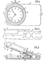
- La fig. 1 montre une vue de dessus de l'objet de l'invention,
- La fig. 2 est une élévation latérale de la fig. 1,
- La fig. 3 est une coupe selon la ligne III/III de la fig. 1,
- La fig. 4 est une coupe selon la ligne IV/IV de la fig. 2,
- La fig. 5 montre une coupe selon la ligne V/V de la fig. 3,
- La fig. 6 montre une barette de blocage dans la partie grippante de la pince,
- La fig. 7 montre en détail et à grande échelle la barette de blocage de la fig. 6,
- La fig. 8 montre une barette de fixation insérée dans la partie grippante de la pince, et
- la fig. 9 montre la barette de fixation selon la fig. 8 vue de devant.
- Dans la fig. 1, on voit la montre 1 assemblée dans un boîtier 2 et montée dans une pince 3. Comme ordre de grandeur, la pince peut avoir une longueur de 50 mm et une largeur d'environ 27 mm. De préférence, le boîtier et la pince sont moulés en matière plastique. Ceci a l'avantage d'une part de faciliter la production en grande série et d'autre part d'obtenir une montre et une pince très légères et agréables à porter. Il est à remarquer, comme cela ressort en particulier des fig. 2 et 3, que la montre se trouve, par rapport à la charnière 4 de la pince, sur le côté où l'on presse sur la branche 5 de la pince et non sur le côté grippant 6 de celle-ci. Ceci présente l'avantage que la pince avec la montre peut être aussi posée sur une table, entre autre sur la branche inférieure 7 de la pince, de sorte que le cadran de la montre est parfaitement lisible.
- Les fig. 3 et 4 montrent les pièces constitutives de la pince, et il ressort que le procédé d'assemblage de cette pince est extrêmement simple. Outre la branche supérieure 5 et la branche inférieure 7, la pince contient un ressort à lame en forme de U 8. La charnière 4 se compose de chaque côté d'un oeillet 9 à la branche supérieure 5 et d'un oeillet 10 à la branche inférieure 7, l'oeillet 9 étant disposé à côté de l'oeillet 10 et les deux ayant une ouverture 11, respectivement 12, dans laquelles un tenon 13 comprenant, à sa partie frontale dirigée vers l'intérieur une fente 14 pour augmenter la flexibilité et un collier de retenue 15.
- Le procédé d'assemblage ressort des figs. 3 et 4. On superpose les deux branches l'une sur l'autre jusqu'à ce que les deux ouvertures 11 et 12 soient vis-à-vis l'une de l'autre et l'on enfile les deux tenons 13 jusqu'à ce que leur collier 15 se trouve derrière l'oeillet 10. Une fois engagé de cette manière, le tenon 13 ne peut pas être sorti sans détruire le tenon ou les oeillets. Du fait que la tête 16 du tenon vient à fleur des faces latérales des deux branches de la pince, le danger que les tenons sortent est encore diminué, et en plus cette tête 16 sert d'élément décoratif. Une fois les tenons en place, on insère le ressort 8 et pour faciliter son insertion, la surface intérieure de la branches inférieure comporte deux nervures 17. Le ressort 8 est tenu en place dans la branche inférieure 7 par un encadrement constitué de deux parois latérales 18 et d'une paroi transversale 19, et dans la surface intérieure de la branche supérieure 5 par une paroi latérale 31. Pour faciliter l'insertion du ressort, la surface 20 de la paroi latérale 19 peut être en biais.
- La montre 1 se trouve dans un boîtier 2 composé d'un anneau supérieur 21 et d'un anneau inférieur 22. L'anneau inférieur 22 est pourvu de deux nervures 23, se trouvant l'une en face de l'autre, chacune s'étendant sur environ un quart du pourtour et s'insérant dans une ouverture correspondante 24 dans la branche supérieure de la pince, cette ouverture étant pourvue de deux épaulements 25 de longueur à peu près égale à celle des nervures 23. Les nervures d'une part et les épaulements d'autre part sont arrangés de telle manière que la montre avec le boîtier ne peut être insérée ou enlevée que dans une position définie seulement, par exemple dans la position 14 h 10. Naturellement, toute autre position peut être définie. Pour protéger la couronne 26, il est préférable de prévoir une protection 27 avec des rainures permettant de tourner la montre aisément à l'aide de cette protection. Comme il ressort de la fig. 2, la montre avec son boîtier ne dépasse pas beaucoup de la surface 37 de la branche supérieure qui est étagée.
- La montre, respectivement la pince, peut être fixée de différentes manières pour être portée. Une première manière est de fixer la branche inférieure 7 au revers d'un veston par une cheville traversant le trou 28 prévu pour une telle fixation, la cheville pouvant être assurée par un moyen de verouillage de cheville. Une deuxil eme manière de fixation est bien sur de fixer la pince avec la montre à n'importe quel objet si prêtant, par exemple, à des vêtements, un sac à main ou objets similaires, à l'aide de la partie grippante 6 de la pince. Il est clair que selon le mode de fixation, la montre peut être tournée de telle manière que le cadran, respectivement l'affichage de la montre puisse être lu aisément. Un autre moyen encore de fixation est illustré aux figs. 6 à 9. Selon les figs. 6 et 7, on peut prévoir une barette de blocage 29 avec une section allongée en forme de "8", cette barette de blocage étant insérée de côté dans les deux demi-cercles 30 ménagés dans les deux branches de la pince. La barette de blocage est pourvue dans sa partie médiane, d'une anse 32 avec une ouverture transversale 33. La montre, respectivement la pince, pourvue de cette barette de blocage peut être aisément transportée et mise en poche telle quelle, car toute la pince se présente sous la forme d'un parallélépipède rectangle. Comme il ressort de la fig. 6, la longueur de l'anse est telle qu'elle ne dépasse pas du front de la pince. Il est aussi possible d'enfiler une chaîne ou un élément similaire dans l'ouverture transversale et de transporter la montre à l'aide de cette chaîne, par exemple autour du cou, ou comme une montre de poche. Du fait que la pince est ouverte à son maximum et que la barette de blocage est pourvue d'ailettes, cette barette de blocage ne peut pas être sortie aisément et il n'est pratiquement pas possible de l'arracher par devant sans que l'on s'en aperçoive.
- Une autre manière de fixation est prévue par l'emploi d'une barette de fixation 34, ayant une section allongée avec une dimension telle que la barette ne peut être insérée que par l'avant à l'aide du petit diamètre D, tandis que le grand diamètre G a la même grandeur que le diamètre des deux demi-cercles 30 de la pince en position fermée, de ce fait la barette de fixation peut tourner librement dans cette ouverture et ne peut être sortie que dans une position déterminée. Des deux côtés et en dehors de la pince, la barette de fixation est pourvue d'une partie de fixation avec un collier 35 ayant un diamètre extérieur égal à la hauteur de la pince fermée et étant pourvu d'un oeillet 36 pour recevoir une chaînette ou élément similaire.
- Il ressort de la description que la montre avec la pince peut aussi être posée de différentes manières sur une surface, par exemple une table, c'est-à-dire soit sur la branche inférieure ou sur les deux bouts des branches, ou alors sur les côtés latéraux des deux branches. Ceci est possible grâce à la possibilité de pouvoir tourner librement la montre avec le boîtier dans la branche supérieure de la pince. Finalement, il est possible d'enlever la montre et de la remplacer par d'autres objets, par exemple par un bijou. Il ressort en outre et en particulier de la fig. 1 que la surface supérieure composée du cadran de la montre et de la surface de la branche supérieure de la pince est particulièrement bien destinée à être décorée de différentes manières ou à servir de surface de publicité. Ni les dimensions indiquées plus haut, ni le matériel sont limitatifs dans le cadre de cette invention. Il est tout-à-fait possible de prévoir par exemple des montres et des pinces de plus petites dimensions et de les fabriquer par exemple entièrement en métal, voir en métal précieux, ou alors de prévoir des montres et des pinces de plus grandes dimension pouvant faire des objets de mode et de publicité. Il est clair que le mouvement et l'affichage ne sont pas limités à un affichage analogique dessiné, mais il est possible aussi de prévoir des montres digitales ou des montres analogiques digitales, pouvant être ajustées de manière à être parfaitement visibles dans toutes les positions désirées.
Claims (7)
Priority Applications (10)
| Application Number | Priority Date | Filing Date | Title |
|---|---|---|---|
| DE8686810155T DE3661161D1 (en) | 1986-04-01 | 1986-04-01 | Watch mounted on a clip |
| EP86810155A EP0226533B1 (fr) | 1986-04-01 | 1986-04-01 | Montre montée sur une pince |
| AT86810155T ATE38569T1 (de) | 1986-04-01 | 1986-04-01 | An einer klammer montierte uhr. |
| CA000530301A CA1311927C (fr) | 1986-04-01 | 1987-02-23 | Montre sur pince |
| DE8703197U DE8703197U1 (de) | 1986-04-01 | 1987-03-02 | Uhr auf einer Klammer |
| JP62053912A JPS62233782A (ja) | 1986-04-01 | 1987-03-09 | 時計とクリツプとの組合わせ |
| US07/026,180 US4705408A (en) | 1986-04-01 | 1987-03-16 | Watch mounted on a clip |
| AU70413/87A AU582494B2 (en) | 1986-04-01 | 1987-03-19 | A watch mounted on a clip |
| CN87102352A CN1014472B (zh) | 1986-04-01 | 1987-03-28 | 一种装在夹子上的表 |
| KR1019870002926A KR940002725B1 (ko) | 1986-04-01 | 1987-03-30 | 클립에 장착된 시계 |
Applications Claiming Priority (1)
| Application Number | Priority Date | Filing Date | Title |
|---|---|---|---|
| EP86810155A EP0226533B1 (fr) | 1986-04-01 | 1986-04-01 | Montre montée sur une pince |
Publications (2)
| Publication Number | Publication Date |
|---|---|
| EP0226533A1 true EP0226533A1 (fr) | 1987-06-24 |
| EP0226533B1 EP0226533B1 (fr) | 1988-11-09 |
Family
ID=8196456
Family Applications (1)
| Application Number | Title | Priority Date | Filing Date |
|---|---|---|---|
| EP86810155A Expired EP0226533B1 (fr) | 1986-04-01 | 1986-04-01 | Montre montée sur une pince |
Country Status (9)
| Country | Link |
|---|---|
| US (1) | US4705408A (fr) |
| EP (1) | EP0226533B1 (fr) |
| JP (1) | JPS62233782A (fr) |
| KR (1) | KR940002725B1 (fr) |
| CN (1) | CN1014472B (fr) |
| AT (1) | ATE38569T1 (fr) |
| AU (1) | AU582494B2 (fr) |
| CA (1) | CA1311927C (fr) |
| DE (2) | DE3661161D1 (fr) |
Cited By (1)
| Publication number | Priority date | Publication date | Assignee | Title |
|---|---|---|---|---|
| EP0358611A1 (fr) * | 1988-09-07 | 1990-03-14 | Arieh-Courvoisier S.A. | Agrafe |
Families Citing this family (61)
| Publication number | Priority date | Publication date | Assignee | Title |
|---|---|---|---|---|
| USD301017S (en) | 1985-12-06 | 1989-05-09 | Instrumentverken Ab | Orienteering compass |
| USD312220S (en) | 1986-10-31 | 1990-11-20 | Seikosha Co., Ltd. | Travel alarm clock with flashlight |
| USD312415S (en) | 1987-02-25 | 1990-11-27 | Bernard Muller | Combined watch and clip |
| USD313758S (en) | 1987-05-04 | 1991-01-15 | Prasenta KG, Weber & Co. | Combined digital watch and clip |
| USD313759S (en) | 1987-08-07 | 1991-01-15 | Twinbird Industrial Company Limited | Combined clock and clip |
| DE3735495A1 (de) * | 1987-10-20 | 1989-03-16 | Hemmerle Kg Geb | Tragbare uhr mit uhrgehaeuse und haltevorrichtung |
| USD323469S (en) | 1989-07-03 | 1992-01-28 | Seiko Epson Corporation | Electronic metronome with clip |
| USD331196S (en) | 1990-08-01 | 1992-11-24 | Tseng Yu-Seng | Waist-belt clock |
| AU115116S (en) | 1991-08-27 | 1992-09-14 | Guzzini Flii Spa | Stand |
| USD373357S (en) | 1995-01-10 | 1996-09-03 | Ballanda Limited | Clock radio |
| US5610877A (en) * | 1995-01-20 | 1997-03-11 | Adams; Kathy S. | Fabric attachable timepiece |
| US6295703B1 (en) | 1999-09-07 | 2001-10-02 | Clip It 2, Inc. | Device for attaching objects to fabric |
| USD447423S1 (en) | 1999-11-30 | 2001-09-04 | Pollyflame International B.V. | Clock |
| US20030156500A1 (en) * | 2002-02-21 | 2003-08-21 | Popowich Lisa B. | Watch |
| USD492359S1 (en) | 2002-09-10 | 2004-06-29 | Sun Coast Merchandise Corp. | Memo holder with display |
| US7048433B1 (en) | 2002-09-10 | 2006-05-23 | Sun Coast Merchandise Corp. | Self-righting, variable-orientation display assembly |
| US6595683B1 (en) | 2002-09-10 | 2003-07-22 | Carl Cetera | Self-righting, variable-orientation display assembly |
| US6873574B1 (en) | 2003-02-10 | 2005-03-29 | Scott M. Gotthard | Body jewelry watch |
| US6920975B1 (en) * | 2003-05-29 | 2005-07-26 | The Gem Group | Clock for notepad cover flap |
| US20050166704A1 (en) * | 2004-01-30 | 2005-08-04 | Yuan-Hsin Huang | Bicycle handlebar clock mounting structure |
| US7167419B2 (en) * | 2004-03-17 | 2007-01-23 | Newco Enterprises, Inc. | Beverage brewer timer |
| US7281877B1 (en) | 2004-08-20 | 2007-10-16 | The Gem Group, Inc. | Padfolio with work area |
| USD532316S1 (en) * | 2005-02-17 | 2006-11-21 | Vessel, Inc. | Clip watch |
| US20070036037A1 (en) * | 2005-08-12 | 2007-02-15 | Vessel, Inc. | Clipable timepiece |
| US20060083115A1 (en) * | 2005-12-02 | 2006-04-20 | Ronald Lafever | Flexible band with clip-on watch |
| US20070153639A1 (en) * | 2005-12-02 | 2007-07-05 | Ronald Lafever | Flexible band with clip-on watch |
| USD537737S1 (en) | 2006-03-10 | 2007-03-06 | Callanen International | Watch casing |
| US20070211578A1 (en) * | 2006-03-13 | 2007-09-13 | Theresa Frank | Watch and clip |
| USD574226S1 (en) * | 2007-04-25 | 2008-08-05 | Wolff Stephen H | Rectangular clip |
| USD576889S1 (en) * | 2008-02-07 | 2008-09-16 | Gmpc, Llc | Clip clock |
| USD596508S1 (en) * | 2008-07-25 | 2009-07-21 | Willie Lee Warren | Money clip |
| USD591501S1 (en) | 2008-10-09 | 2009-05-05 | Perkowski Dara A | Clock purse |
| USD614051S1 (en) * | 2009-09-16 | 2010-04-20 | Cooney Gerald A | Clip-on timer |
| USD714166S1 (en) * | 2012-06-27 | 2014-09-30 | Sieko Instruments Inc. | Metronome |
| US10528135B2 (en) | 2013-01-14 | 2020-01-07 | Ctrl-Labs Corporation | Wearable muscle interface systems, devices and methods that interact with content displayed on an electronic display |
| US10152082B2 (en) | 2013-05-13 | 2018-12-11 | North Inc. | Systems, articles and methods for wearable electronic devices that accommodate different user forms |
| US10042422B2 (en) | 2013-11-12 | 2018-08-07 | Thalmic Labs Inc. | Systems, articles, and methods for capacitive electromyography sensors |
| US10188309B2 (en) | 2013-11-27 | 2019-01-29 | North Inc. | Systems, articles, and methods for electromyography sensors |
| US12504816B2 (en) | 2013-08-16 | 2025-12-23 | Meta Platforms Technologies, Llc | Wearable devices and associated band structures for sensing neuromuscular signals using sensor pairs in respective pods with communicative pathways to a common processor |
| US11921471B2 (en) | 2013-08-16 | 2024-03-05 | Meta Platforms Technologies, Llc | Systems, articles, and methods for wearable devices having secondary power sources in links of a band for providing secondary power in addition to a primary power source |
| US20150124566A1 (en) | 2013-10-04 | 2015-05-07 | Thalmic Labs Inc. | Systems, articles and methods for wearable electronic devices employing contact sensors |
| US10199008B2 (en) | 2014-03-27 | 2019-02-05 | North Inc. | Systems, devices, and methods for wearable electronic devices as state machines |
| US9880632B2 (en) | 2014-06-19 | 2018-01-30 | Thalmic Labs Inc. | Systems, devices, and methods for gesture identification |
| US9597918B2 (en) * | 2014-09-30 | 2017-03-21 | Michael Joseph Jersa, III | Smart clip |
| US10078435B2 (en) | 2015-04-24 | 2018-09-18 | Thalmic Labs Inc. | Systems, methods, and computer program products for interacting with electronically displayed presentation materials |
| WO2018022602A1 (fr) | 2016-07-25 | 2018-02-01 | Ctrl-Labs Corporation | Procédés et appareil permettant de prédire des informations de position musculo-squelettique à l'aide de capteurs autonomes portables |
| US11216069B2 (en) | 2018-05-08 | 2022-01-04 | Facebook Technologies, Llc | Systems and methods for improved speech recognition using neuromuscular information |
| US11635736B2 (en) | 2017-10-19 | 2023-04-25 | Meta Platforms Technologies, Llc | Systems and methods for identifying biological structures associated with neuromuscular source signals |
| WO2020112986A1 (fr) | 2018-11-27 | 2020-06-04 | Facebook Technologies, Inc. | Procédés et appareil d'auto-étalonnage d'un système de capteur à électrode vestimentaire |
| US12554325B2 (en) | 2016-07-25 | 2026-02-17 | Meta Platforms Technologies, Llc | Methods and apparatuses for low latency body state prediction based on neuromuscular data |
| US11961494B1 (en) | 2019-03-29 | 2024-04-16 | Meta Platforms Technologies, Llc | Electromagnetic interference reduction in extended reality environments |
| US10937414B2 (en) | 2018-05-08 | 2021-03-02 | Facebook Technologies, Llc | Systems and methods for text input using neuromuscular information |
| US11493993B2 (en) | 2019-09-04 | 2022-11-08 | Meta Platforms Technologies, Llc | Systems, methods, and interfaces for performing inputs based on neuromuscular control |
| US11907423B2 (en) | 2019-11-25 | 2024-02-20 | Meta Platforms Technologies, Llc | Systems and methods for contextualized interactions with an environment |
| US11481030B2 (en) | 2019-03-29 | 2022-10-25 | Meta Platforms Technologies, Llc | Methods and apparatus for gesture detection and classification |
| US11150730B1 (en) | 2019-04-30 | 2021-10-19 | Facebook Technologies, Llc | Devices, systems, and methods for controlling computing devices via neuromuscular signals of users |
| US12579768B2 (en) | 2018-01-25 | 2026-03-17 | Meta Platforms Technologies, Llc | Wearable electronic devices, extended reality systems including neuromuscular sensors, and methods for generating text from speech input and modifying the generated text based on neuromuscular data |
| US10592001B2 (en) | 2018-05-08 | 2020-03-17 | Facebook Technologies, Llc | Systems and methods for improved speech recognition using neuromuscular information |
| EP3843617B1 (fr) | 2018-08-31 | 2023-10-04 | Facebook Technologies, LLC. | Interprétation de signaux neuromusculaires guidée par caméra |
| CN112789577B (zh) | 2018-09-20 | 2024-04-05 | 元平台技术有限公司 | 增强现实系统中的神经肌肉文本输入、书写和绘图 |
| US11868531B1 (en) | 2021-04-08 | 2024-01-09 | Meta Platforms Technologies, Llc | Wearable device providing for thumb-to-finger-based input gestures detected based on neuromuscular signals, and systems and methods of use thereof |
Citations (6)
| Publication number | Priority date | Publication date | Assignee | Title |
|---|---|---|---|---|
| FR40538E (fr) * | 1930-03-21 | 1932-07-22 | Jaeger Ets Ed | Charnière à verrou pour toutes applications et notamment pour les articles de bijouterie |
| US3312435A (en) * | 1964-09-08 | 1967-04-04 | Harold H Malone | Mounting means |
| DE1750392A1 (de) * | 1968-04-11 | 1970-11-12 | Gossler Kg Oscar | Vorrichtung zum Anschluss einer elektrischen Leitung an einen Schlauch |
| FR2461970A1 (fr) * | 1979-07-20 | 1981-02-06 | Vdo Schindling | Montre equipee d'un support |
| NL7909240A (nl) * | 1979-12-21 | 1981-07-16 | Patrijslaan 1A Te 1272 Px Huizen. | Horloge-kast. |
| EP0080563A2 (fr) * | 1981-11-26 | 1983-06-08 | VDO Adolf Schindling AG | Boîtier de pendule |
Family Cites Families (8)
| Publication number | Priority date | Publication date | Assignee | Title |
|---|---|---|---|---|
| US1466505A (en) * | 1921-03-28 | 1923-08-28 | C F Rumpp & Sons Inc | Traveling case for watches |
| CH169090A (de) * | 1933-05-31 | 1934-05-15 | Wilhelm Becker Fa | Vorrichtung zur Aufnahme einer Armbanduhr, um deren Benutzung als Ansteck- und Tischuhr zu ermöglichen. |
| US2181753A (en) * | 1938-06-10 | 1939-11-28 | Illinois Watch Case Co | Watchcase mounting |
| US2509428A (en) * | 1949-11-01 | 1950-05-30 | Greene Wallace | Wrist watch attachment |
| JPS5720684B2 (fr) * | 1974-11-07 | 1982-04-30 | ||
| JPS5561975A (en) * | 1978-11-02 | 1980-05-10 | Tomitaro Kobayashi | Clarification apparatus for rain water, etc. |
| DE2929373C2 (de) * | 1979-07-20 | 1982-09-23 | Vdo Adolf Schindling Ag, 6000 Frankfurt | Uhrgehäuse mit lösbarer Halterung |
| DE3143546A1 (de) * | 1981-11-03 | 1983-06-30 | Matthias Design Corp., 90210 Beverly Hills, Calif. | Anklemmbare uhr |
-
1986
- 1986-04-01 AT AT86810155T patent/ATE38569T1/de not_active IP Right Cessation
- 1986-04-01 DE DE8686810155T patent/DE3661161D1/de not_active Expired
- 1986-04-01 EP EP86810155A patent/EP0226533B1/fr not_active Expired
-
1987
- 1987-02-23 CA CA000530301A patent/CA1311927C/fr not_active Expired - Lifetime
- 1987-03-02 DE DE8703197U patent/DE8703197U1/de not_active Expired
- 1987-03-09 JP JP62053912A patent/JPS62233782A/ja active Pending
- 1987-03-16 US US07/026,180 patent/US4705408A/en not_active Expired - Fee Related
- 1987-03-19 AU AU70413/87A patent/AU582494B2/en not_active Ceased
- 1987-03-28 CN CN87102352A patent/CN1014472B/zh not_active Expired
- 1987-03-30 KR KR1019870002926A patent/KR940002725B1/ko not_active Expired - Fee Related
Patent Citations (6)
| Publication number | Priority date | Publication date | Assignee | Title |
|---|---|---|---|---|
| FR40538E (fr) * | 1930-03-21 | 1932-07-22 | Jaeger Ets Ed | Charnière à verrou pour toutes applications et notamment pour les articles de bijouterie |
| US3312435A (en) * | 1964-09-08 | 1967-04-04 | Harold H Malone | Mounting means |
| DE1750392A1 (de) * | 1968-04-11 | 1970-11-12 | Gossler Kg Oscar | Vorrichtung zum Anschluss einer elektrischen Leitung an einen Schlauch |
| FR2461970A1 (fr) * | 1979-07-20 | 1981-02-06 | Vdo Schindling | Montre equipee d'un support |
| NL7909240A (nl) * | 1979-12-21 | 1981-07-16 | Patrijslaan 1A Te 1272 Px Huizen. | Horloge-kast. |
| EP0080563A2 (fr) * | 1981-11-26 | 1983-06-08 | VDO Adolf Schindling AG | Boîtier de pendule |
Cited By (2)
| Publication number | Priority date | Publication date | Assignee | Title |
|---|---|---|---|---|
| EP0358611A1 (fr) * | 1988-09-07 | 1990-03-14 | Arieh-Courvoisier S.A. | Agrafe |
| CH674438GA3 (fr) * | 1988-09-07 | 1990-06-15 |
Also Published As
| Publication number | Publication date |
|---|---|
| JPS62233782A (ja) | 1987-10-14 |
| KR940002725B1 (ko) | 1994-03-31 |
| AU582494B2 (en) | 1989-03-23 |
| EP0226533B1 (fr) | 1988-11-09 |
| ATE38569T1 (de) | 1988-11-15 |
| CN87102352A (zh) | 1987-12-09 |
| KR870010423A (ko) | 1987-11-30 |
| DE8703197U1 (de) | 1987-04-16 |
| DE3661161D1 (en) | 1988-12-15 |
| CA1311927C (fr) | 1992-12-29 |
| US4705408A (en) | 1987-11-10 |
| AU7041387A (en) | 1987-07-02 |
| CN1014472B (zh) | 1991-10-23 |
Similar Documents
| Publication | Publication Date | Title |
|---|---|---|
| EP0226533B1 (fr) | Montre montée sur une pince | |
| BE1000021A6 (fr) | Tete de cle et cle pourvue d'une telle tete. | |
| EP0541001B1 (fr) | Boîte de montre avec un fond séparable | |
| FR2757449A1 (fr) | Instrument d'ecriture, notamment un stylo | |
| EP0280963A1 (fr) | Montre couverte d'une coiffe et procédé de montage d'une telle montre | |
| EP0770939A1 (fr) | Pièce d'horlogerie comprenant un boîtier dans lequel est logé un mouvement horloger | |
| EP0351705A1 (fr) | Boîte de montre recouverte d'une coiffe accrochée à la carrure | |
| EP1404190A1 (fr) | Anneau ouvert articule | |
| EP0600389B1 (fr) | Boîte de montre à carrure évidée | |
| EP1047982A1 (fr) | Boite de montre | |
| WO1989003646A1 (fr) | Bijou a elements constitutifs interchangeables | |
| WO1981002970A1 (fr) | Assemblage elastique par exemple bracelet ou bague | |
| EP2120625B1 (fr) | Bracelet pour montre | |
| FR2547430A3 (fr) | Lunettes avec des moyens pour l'application interchangeable d'une plaquette en materiau decoratif | |
| CH682290A5 (en) | Wrist watch bracelet - has holder between two sections of bracelet on opposite side to watch, designed to hold second instrument or container | |
| EP0979046A1 (fr) | Bracelet de montre ou de bijou avec maillons articules et garnitures souples | |
| FR2965073A3 (fr) | Montre | |
| WO1983002014A1 (fr) | Montre-bracelet | |
| EP0446176B1 (fr) | Boîte de montre | |
| CH463068A (de) | Verbundplatte und Verfahren zu ihrer Herstellung | |
| EP0923890B1 (fr) | Bracelet | |
| CH289760A (fr) | Montre-bracelet. | |
| FR2562398A1 (fr) | Bracelet a maillons | |
| EP0383180A1 (fr) | Montre-bracelet comportant un bracelet et une boîte | |
| CH474070A (fr) | Appareil photographique |
Legal Events
| Date | Code | Title | Description |
|---|---|---|---|
| PUAI | Public reference made under article 153(3) epc to a published international application that has entered the european phase |
Free format text: ORIGINAL CODE: 0009012 |
|
| 17P | Request for examination filed |
Effective date: 19870205 |
|
| AK | Designated contracting states |
Kind code of ref document: A1 Designated state(s): AT BE CH DE FR GB IT LI LU NL SE |
|
| 17Q | First examination report despatched |
Effective date: 19871110 |
|
| GRAA | (expected) grant |
Free format text: ORIGINAL CODE: 0009210 |
|
| AK | Designated contracting states |
Kind code of ref document: B1 Designated state(s): AT BE CH DE FR GB IT LI LU NL SE |
|
| REF | Corresponds to: |
Ref document number: 38569 Country of ref document: AT Date of ref document: 19881115 Kind code of ref document: T |
|
| ITF | It: translation for a ep patent filed | ||
| GBT | Gb: translation of ep patent filed (gb section 77(6)(a)/1977) | ||
| REF | Corresponds to: |
Ref document number: 3661161 Country of ref document: DE Date of ref document: 19881215 |
|
| PLBE | No opposition filed within time limit |
Free format text: ORIGINAL CODE: 0009261 |
|
| STAA | Information on the status of an ep patent application or granted ep patent |
Free format text: STATUS: NO OPPOSITION FILED WITHIN TIME LIMIT |
|
| 26N | No opposition filed | ||
| ITTA | It: last paid annual fee | ||
| EPTA | Lu: last paid annual fee | ||
| EAL | Se: european patent in force in sweden |
Ref document number: 86810155.1 |
|
| PGFP | Annual fee paid to national office [announced via postgrant information from national office to epo] |
Ref country code: GB Payment date: 19960409 Year of fee payment: 11 |
|
| PGFP | Annual fee paid to national office [announced via postgrant information from national office to epo] |
Ref country code: FR Payment date: 19960410 Year of fee payment: 11 |
|
| PGFP | Annual fee paid to national office [announced via postgrant information from national office to epo] |
Ref country code: AT Payment date: 19960411 Year of fee payment: 11 |
|
| PGFP | Annual fee paid to national office [announced via postgrant information from national office to epo] |
Ref country code: SE Payment date: 19960417 Year of fee payment: 11 |
|
| PGFP | Annual fee paid to national office [announced via postgrant information from national office to epo] |
Ref country code: DE Payment date: 19960418 Year of fee payment: 11 |
|
| PGFP | Annual fee paid to national office [announced via postgrant information from national office to epo] |
Ref country code: NL Payment date: 19960430 Year of fee payment: 11 |
|
| PGFP | Annual fee paid to national office [announced via postgrant information from national office to epo] |
Ref country code: LU Payment date: 19960501 Year of fee payment: 11 |
|
| PGFP | Annual fee paid to national office [announced via postgrant information from national office to epo] |
Ref country code: BE Payment date: 19960612 Year of fee payment: 11 |
|
| PGFP | Annual fee paid to national office [announced via postgrant information from national office to epo] |
Ref country code: CH Payment date: 19960802 Year of fee payment: 11 |
|
| PG25 | Lapsed in a contracting state [announced via postgrant information from national office to epo] |
Ref country code: LU Free format text: LAPSE BECAUSE OF NON-PAYMENT OF DUE FEES Effective date: 19970401 Ref country code: GB Effective date: 19970401 Ref country code: AT Effective date: 19970401 |
|
| PG25 | Lapsed in a contracting state [announced via postgrant information from national office to epo] |
Ref country code: SE Effective date: 19970402 |
|
| PG25 | Lapsed in a contracting state [announced via postgrant information from national office to epo] |
Ref country code: LI Free format text: LAPSE BECAUSE OF NON-PAYMENT OF DUE FEES Effective date: 19970430 Ref country code: CH Free format text: LAPSE BECAUSE OF NON-PAYMENT OF DUE FEES Effective date: 19970430 Ref country code: BE Effective date: 19970430 |
|
| BERE | Be: lapsed |
Owner name: S.A. ALTOP Effective date: 19970430 |
|
| PG25 | Lapsed in a contracting state [announced via postgrant information from national office to epo] |
Ref country code: NL Effective date: 19971101 |
|
| GBPC | Gb: european patent ceased through non-payment of renewal fee |
Effective date: 19970401 |
|
| REG | Reference to a national code |
Ref country code: CH Ref legal event code: PL |
|
| PG25 | Lapsed in a contracting state [announced via postgrant information from national office to epo] |
Ref country code: FR Free format text: LAPSE BECAUSE OF NON-PAYMENT OF DUE FEES Effective date: 19971231 |
|
| PG25 | Lapsed in a contracting state [announced via postgrant information from national office to epo] |
Ref country code: DE Free format text: LAPSE BECAUSE OF NON-PAYMENT OF DUE FEES Effective date: 19980101 |
|
| NLV4 | Nl: lapsed or anulled due to non-payment of the annual fee |
Effective date: 19971101 |
|
| EUG | Se: european patent has lapsed |
Ref document number: 86810155.1 |
|
| REG | Reference to a national code |
Ref country code: FR Ref legal event code: ST |
|
| PG25 | Lapsed in a contracting state [announced via postgrant information from national office to epo] |
Ref country code: IT Free format text: LAPSE BECAUSE OF NON-PAYMENT OF DUE FEES;WARNING: LAPSES OF ITALIAN PATENTS WITH EFFECTIVE DATE BEFORE 2007 MAY HAVE OCCURRED AT ANY TIME BEFORE 2007. THE CORRECT EFFECTIVE DATE MAY BE DIFFERENT FROM THE ONE RECORDED. Effective date: 20050401 |