EP0226657B1 - Vorrichtung zum Antreiben des Arbeitswerkzeuges eines Baggers - Google Patents
Vorrichtung zum Antreiben des Arbeitswerkzeuges eines Baggers Download PDFInfo
- Publication number
- EP0226657B1 EP0226657B1 EP85116472A EP85116472A EP0226657B1 EP 0226657 B1 EP0226657 B1 EP 0226657B1 EP 85116472 A EP85116472 A EP 85116472A EP 85116472 A EP85116472 A EP 85116472A EP 0226657 B1 EP0226657 B1 EP 0226657B1
- Authority
- EP
- European Patent Office
- Prior art keywords
- boom
- arm
- cylinder
- working element
- hollow
- Prior art date
- Legal status (The legal status is an assumption and is not a legal conclusion. Google has not performed a legal analysis and makes no representation as to the accuracy of the status listed.)
- Expired
Links
- 238000004519 manufacturing process Methods 0.000 description 5
- 238000005452 bending Methods 0.000 description 3
- 238000000034 method Methods 0.000 description 3
- 230000008569 process Effects 0.000 description 3
- 230000000903 blocking effect Effects 0.000 description 2
- 230000006872 improvement Effects 0.000 description 2
- 230000036544 posture Effects 0.000 description 2
- 238000005266 casting Methods 0.000 description 1
- 230000008859 change Effects 0.000 description 1
- 238000010276 construction Methods 0.000 description 1
- 230000007423 decrease Effects 0.000 description 1
- 238000010586 diagram Methods 0.000 description 1
- 230000002708 enhancing effect Effects 0.000 description 1
- 238000003780 insertion Methods 0.000 description 1
- 230000037431 insertion Effects 0.000 description 1
- 239000002184 metal Substances 0.000 description 1
- 238000012986 modification Methods 0.000 description 1
- 230000004048 modification Effects 0.000 description 1
- 230000009467 reduction Effects 0.000 description 1
- 230000002787 reinforcement Effects 0.000 description 1
- 230000000153 supplemental effect Effects 0.000 description 1
- 238000003466 welding Methods 0.000 description 1
Images

Classifications
-
- E—FIXED CONSTRUCTIONS
- E02—HYDRAULIC ENGINEERING; FOUNDATIONS; SOIL SHIFTING
- E02F—DREDGING; SOIL-SHIFTING
- E02F3/00—Dredgers; Soil-shifting machines
- E02F3/04—Dredgers; Soil-shifting machines mechanically-driven
- E02F3/28—Dredgers; Soil-shifting machines mechanically-driven with digging tools mounted on a dipper- or bucket-arm, i.e. there is either one arm or a pair of arms, e.g. dippers, buckets
- E02F3/30—Dredgers; Soil-shifting machines mechanically-driven with digging tools mounted on a dipper- or bucket-arm, i.e. there is either one arm or a pair of arms, e.g. dippers, buckets with a dipper-arm pivoted on a cantilever beam, i.e. boom
- E02F3/32—Dredgers; Soil-shifting machines mechanically-driven with digging tools mounted on a dipper- or bucket-arm, i.e. there is either one arm or a pair of arms, e.g. dippers, buckets with a dipper-arm pivoted on a cantilever beam, i.e. boom working downwardly and towards the machine, e.g. with backhoes
-
- E—FIXED CONSTRUCTIONS
- E02—HYDRAULIC ENGINEERING; FOUNDATIONS; SOIL SHIFTING
- E02F—DREDGING; SOIL-SHIFTING
- E02F3/00—Dredgers; Soil-shifting machines
- E02F3/04—Dredgers; Soil-shifting machines mechanically-driven
- E02F3/28—Dredgers; Soil-shifting machines mechanically-driven with digging tools mounted on a dipper- or bucket-arm, i.e. there is either one arm or a pair of arms, e.g. dippers, buckets
- E02F3/30—Dredgers; Soil-shifting machines mechanically-driven with digging tools mounted on a dipper- or bucket-arm, i.e. there is either one arm or a pair of arms, e.g. dippers, buckets with a dipper-arm pivoted on a cantilever beam, i.e. boom
-
- E—FIXED CONSTRUCTIONS
- E02—HYDRAULIC ENGINEERING; FOUNDATIONS; SOIL SHIFTING
- E02F—DREDGING; SOIL-SHIFTING
- E02F3/00—Dredgers; Soil-shifting machines
- E02F3/04—Dredgers; Soil-shifting machines mechanically-driven
- E02F3/28—Dredgers; Soil-shifting machines mechanically-driven with digging tools mounted on a dipper- or bucket-arm, i.e. there is either one arm or a pair of arms, e.g. dippers, buckets
- E02F3/36—Component parts
- E02F3/38—Cantilever beams, i.e. booms;, e.g. manufacturing processes, forms, geometry or materials used for booms; Dipper-arms, e.g. manufacturing processes, forms, geometry or materials used for dipper-arms; Bucket-arms
Definitions
- This invention relates to an apparatus for the operation of the working element of an excavator such as a power shovel, and particularly pertains to the construction for attachment of the apparatus to the excavator.
- the aforementioned hydraulic cylinders for retaining and changing the postures of the boom, the arm, and the bucket independently of each other are generally disposed on the outer walls along the aforementioned members, the configuration of the working extension (consisting of the hydraulic cylinders, the boom, and the arm) has no neat appearance from the aesthetic point of view.
- the document US-A- 3 057 494 discloses an excavating apparatus composed of articulated arms which are actuated by hydraulic cylinders, wherein the cylinders are protected from damage.
- the apparatus includes a housing, to the outer portion of which is fastened a vertically-elongated support member being capable of swinging relative to the housing. Attached to the support member for pivotal movement about a horizontal axis is a boom. Attached to the boom at a position somewhat removed from its outer end is a dipper stick, having a bucket pivotally attached to its lower end.
- a boom cylinder is attached at one end to the lower part of the support member and the other end is pivotally attached to an intermediate portion of the boom.
- a second hydraulic dipper stick cylinder is connected at one end to the outer end of the boom and at its other end to an intermediate portion of the dipper stick.
- a third hydraulic bucket cylinder is connected at one end to an intermediate portion of the dipper stick and at the other end to the bucket at a point considerably spaced from the point of attachment of the dipper stick thereto.
- the boom is of triangular form and hollow, at least a portion of the boom cylinder residing within the boom. Generally speaking, the boom is formed with triangularly-shaped side walls joint by edge walls on two long sides of the triangle only. The third, short side is open to receive the cylinder.
- the dipper stick also is provided with side walls of a generally triangular shape and with an open edge for reception of the dipper stick cylinder, and also is provided with a supplemental open edge, thus permitting the two side walls to embrace the upper part of the boom.
- An object of the invention as claimed is to overcome the aforementioned problems of the prior art and provide an apparatus for the operation of working elements of an excavator, which permits reinforcement of the strength of the boom and the arm and, at the same time, ensures enhancement of the aesthetic sense.
- Another object of this invention is to provide an apparatus for the operation of the working elements of an excavator or the configuration of the attachment of the apparatus, which permits reduction in bending and torsional moments exerted on the boom and the arm and simplification of the process of fabrication.
- the present invention has, as its point of departure, provision of an improvement in an apparatus for the operation of a working element of an excavator provided with a boom, an arm connected at the rear end to the leading end of the boom and at the leading end thereof to the working element, a boom cylinder connected at one end thereof to the boom and adapted to impart a vertical rotary movement to the boom, an arm cylinder connected at one end thereof to the boom and at the other end thereof to the rear end of the arm and adapted to operate the arm, and a working element cylinder connected at one end thereof to the arm and at the other end thereof to the working element and adapted to operate the working element, which improvement comprises the boom and/or the arm being each fabricated in the shape of a hollow tube having the opposite ends thereof left unclosed and at least one cylinder selected from the group consisting of the boom cylinder, the arm cylinder, and the working element cylinder being disposed as enclosed in the boom and/or the arm.
- the invention is particularly characterized in that the boom having its opposite ends left open, includes an intermediate boom member having a bent portion, and the point of connection of the boom cylinder to the boom and the point of connection of the arm cylinder to the boom constitutes a joint fulcrum which is formed in the central part of the bent portion of the intermediate boom member.
- the present invention is particularly characterized in that the boom including an elbow-shaped hollow intermediate boom member is composed of a hollow front boom member and a hollow rear boom member attached fast to the opposite ends of the intermediate boom member, a connecting member attached fast to the end of the hollow rear boom member and adapted to connect the boom to fixing means serving to support the boom in place, and a connecting member attached fast to the end of the hollow front boom member and adapted to connect the boom to the arm, the intermediate, front, and rear boom members each possessing a circular or elliptic section.
- numeral 1 stands for a vehicular body of an excavator possessing a track type undercarriage 2 and rotatably mounted on the undercarriage.
- the apparatus for operating a bucket 3 as the working element comprises a boom 4 attached to the vehicular body 1 in a manner enabling the boom 4 to generate a vertical rotary movement and an arm 5 attached swingably at one end thereof to the aforementioned boom 4 and attached at the other end thereof to the bucket 3 in such a manner that the bucket 3 will be allowed to rotate in the vertical direction about the point of attachment.
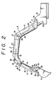
- the boom 4 has a main body consisting of a linear rear boom member 6, a linear front boom member 7, and an elbow-shaped intermediate boom member 8 interconnecting the first two boom members fast to each other in such a manner that the three boom members will jointly assume the shape of diverged legs of the letter L.
- the front, rear, and intermediate boom members 7, 6 and 8 are each fabricated in the shape of a hollow tube of a circular or elliptic cross section.
- the rear boom member 6 is attached fast at the rear end thereof to a connecting member possessing a two-prong forked bracket 11.
- the forked bracket 11 is so shaped that the lower end thereof will protrude outwardly from the rear boom member 6 roughly in the shape of diverged legs of the letter L.
- the forked bracket 12 is so shaped that the upper end thereof will protrude inwardly from the aforementioned front boom member 7 roughly in the shape of diverged legs of the letter L.
- the aforementioned connecting members 9 and 10 may be formed by casting or fabricated with sheet metal pieces. They avoid blocking the rear end of the rear boom member 6 and the leading end of the front boom member 7.
- the boom 4 fabricated as described above is vertically rotatably attached to the vehicular body 1 by causing the forked bracket 11 of the connecting member 9 to be connected with a shaft pin 14 to the upper part of a support bracket 13 of the vehicular body 1.
- the arm 5 mentioned above possesses a linear arm member 16 fabricated in the shape of a hollow tube of a circular or elliptic section.
- a connecting member 17 possessing an inwardly extended two-prong forked bracket 19 is attached fast to the front end and a connecting member 18 possessing a two-prong forked bracket 20 is attached fast to the rear end respectively of the arm member 16.
- the connecting members 17 and 18 avoid blocking the front end and the rear end of the arm member 16.
- the forked bracket 12 of the front connecting member 10 of the boom 4 is connected with a shaft pin 21 to the rear connecting member 18 rear the arm member 16.
- the upper end of the bucket 3 is connected with a shaft pin 22 to the forked bracket 19 of the front connecting member 17.
- the end of a piston rod 25 of the boom cylinder 23 is connected with a shaft pin 26 to a fulcrum 15 formed at the central bent part of the intermediate boom member 8.
- the boom cylinder 23 is enclosed in the boom 4.
- To the shaft pin 26 of the fulcrum 15 is connected the basal end of an arm cylinder 27.
- the point of connection of the boom cylinder 23 to the boom 4 and the point of connection of the arm cylinder 27 to the boom 4 constitute a joint fulcrum.
- the end of the piston rod 28 of the arm cylinder 27 is connected with a shaft pin 29 to the forked bracket 20 of the rear connecting member 18 of the arm 5.
- the arm cylinder 27 is enclosed with the boom 4.
- the basal end of a working element cylinder 31 is connected to the shaft pin 21 of a connection part 30 between the boom 4 and the arm 5.
- the point of connection of the boom 4 to the arm 5 and the point of connection of the working element cylinder 31 to the arm also constitute a joint fulcrum.
- the other end of the link 33 is connected with a pin 36 to the rear upper end of the bucket 3 and the other end of the link 34 is connected with a pin 37 to the forked bracket 19.
- the boom 4 is raised by extending the boom cylinder 23 and it is lowered by contracting the boom cylinder.
- the arm 5 is swung by actuating the arm cylinder 27 and the bucket 3 is operated by actuating the working element cylinder 31.
- the desire to enhance the strength of the boom 4 and that of the arm 5 can be attained by fabricating the boom and the arm each in the shape of a hollow tube of a circular or elliptic section very stable to withstand torsional load and the desire to improve the appearance of the apparatus as a whole is accomplished by causing hydraulic cylinders to be enclosed with the boom and/or the arm in the shape of the hollow tube.
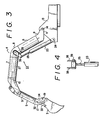
- Fig. 3 and Fig. 4 illustrate other embodiments of this invention. They differ from the embodiment of Fig. 2 in the manner of attachment of the boom cylinder.
- a forked bracket 38 is welded to the opposite lateral parts of the intermediate boom member 8 and extended inwardly therein.
- the end of the piston rod 25 of the boom cylinder 23 is connected with a shaft pin 39 to the leading end of the end of the bracket 38 as illustrated in Fig. 4.
- the arm cylinder 27 and the working element cylinder 31 are enclosed respectively within the hollow tubes of the boom 4 and the arm 5 and the boom cylinder 23 is not enclosed in the boom 4.
- the apparatus therefore, has a neat appearance as compared with the conventional countertype.
- at least one cylinder selected from the group consisting of the boom cylinder 23, the arm cylinder 27, and the working element cylinder 31 can be enclosed within the boom 4 or the arm 5, enabling the apparatus to assume a neat appearance.
Landscapes
- Engineering & Computer Science (AREA)
- Mechanical Engineering (AREA)
- Mining & Mineral Resources (AREA)
- Civil Engineering (AREA)
- General Engineering & Computer Science (AREA)
- Structural Engineering (AREA)
- Jib Cranes (AREA)
- Shovels (AREA)
Claims (5)
Priority Applications (3)
| Application Number | Priority Date | Filing Date | Title |
|---|---|---|---|
| EP85116472A EP0226657B1 (de) | 1985-12-23 | 1985-12-23 | Vorrichtung zum Antreiben des Arbeitswerkzeuges eines Baggers |
| DE8585116472T DE3575755D1 (de) | 1985-12-23 | 1985-12-23 | Vorrichtung zum antreiben des arbeitswerkzeuges eines baggers. |
| US06/814,434 US4686782A (en) | 1985-12-23 | 1985-12-30 | Apparatus for operating working element of excavator |
Applications Claiming Priority (1)
| Application Number | Priority Date | Filing Date | Title |
|---|---|---|---|
| EP85116472A EP0226657B1 (de) | 1985-12-23 | 1985-12-23 | Vorrichtung zum Antreiben des Arbeitswerkzeuges eines Baggers |
Publications (2)
| Publication Number | Publication Date |
|---|---|
| EP0226657A1 EP0226657A1 (de) | 1987-07-01 |
| EP0226657B1 true EP0226657B1 (de) | 1990-01-31 |
Family
ID=8193967
Family Applications (1)
| Application Number | Title | Priority Date | Filing Date |
|---|---|---|---|
| EP85116472A Expired EP0226657B1 (de) | 1985-12-23 | 1985-12-23 | Vorrichtung zum Antreiben des Arbeitswerkzeuges eines Baggers |
Country Status (3)
| Country | Link |
|---|---|
| US (1) | US4686782A (de) |
| EP (1) | EP0226657B1 (de) |
| DE (1) | DE3575755D1 (de) |
Families Citing this family (14)
| Publication number | Priority date | Publication date | Assignee | Title |
|---|---|---|---|---|
| ATE114011T1 (de) * | 1990-03-27 | 1994-11-15 | Atlas Weyhausen Gmbh | Ausleger für einen löffelbagger od. dgl. |
| USD339813S (en) | 1991-06-18 | 1993-09-28 | Case Corporation | Backhoe-style boom |
| US5176491A (en) * | 1991-06-18 | 1993-01-05 | Case Corporation | Overcenter backhoe apparatus |
| DE4134039A1 (de) * | 1991-10-15 | 1993-04-22 | Weimar Werk Baumaschinen Gmbh | Monoblockausleger fuer hydraulische krane und bagger |
| US5486084A (en) * | 1993-06-07 | 1996-01-23 | Raymond F. Pitman | Multiple purpose material handling and working apparatus |
| DE4328449A1 (de) * | 1993-08-24 | 1995-03-02 | Macmoter Spa | Baumaschine, insbesondere Baggerfahrzeug |
| US7698838B1 (en) * | 2005-11-09 | 2010-04-20 | Strayhorn David W | Hoe equipped excavator having increased range |
| JP4566935B2 (ja) * | 2006-03-13 | 2010-10-20 | ヤンマー株式会社 | 掘削作業機のブーム |
| US20100008751A1 (en) * | 2006-07-24 | 2010-01-14 | Daniel Webb | Boom arrangement |
| EP2480726A1 (de) * | 2009-09-21 | 2012-08-01 | Volvo Compact Equipment Sas | Expandierbare kelle mit extrudiertem teil für einen tieflöffelstiel |
| JP5604455B2 (ja) * | 2012-01-16 | 2014-10-08 | 日立建機株式会社 | 建設機械のフロント作業機 |
| ITMI20120206A1 (it) * | 2012-02-14 | 2013-08-15 | Cifa Spa | Segmento di un braccio articolato e braccio articolato comprendente detto segmento |
| WO2018175858A1 (en) | 2017-03-23 | 2018-09-27 | Clark Equipment Company | Power machine with a boom, a boom actuator, an implement and a stop for preventing contact between the boom actuator and the implement |
| DE202021103332U1 (de) | 2021-06-22 | 2021-07-05 | Robert Schreiber | Minibagger mit Verstellausleger |
Family Cites Families (16)
| Publication number | Priority date | Publication date | Assignee | Title |
|---|---|---|---|---|
| US2910190A (en) * | 1955-09-07 | 1959-10-27 | Baas Erwin | Boom arm |
| US3003649A (en) * | 1957-10-23 | 1961-10-10 | Warner Swasey Co | Turntable structure for hydraulic digging machines |
| US3042233A (en) * | 1958-12-15 | 1962-07-03 | Koehring Co | Multiple joint backhoe |
| US3057494A (en) * | 1959-01-30 | 1962-10-09 | Wain Roy Corp | Excavating apparatus |
| US3148788A (en) * | 1961-06-28 | 1964-09-15 | Ferwerda Ray | Digging apparatus |
| US3441154A (en) * | 1966-04-04 | 1969-04-29 | Warner Swasey Co | Material handling machine |
| US3339763A (en) * | 1966-10-14 | 1967-09-05 | Univ Oklahoma State | Automatic back hoe control system |
| US3390794A (en) * | 1967-03-09 | 1968-07-02 | Deere & Co | Extensible and retractable boom |
| GB1249330A (en) * | 1967-10-26 | 1971-10-13 | Orenstein & Koppel Ag | Bucket for a hydraulic excavator |
| US3532234A (en) * | 1968-07-11 | 1970-10-06 | Grant Inc Louis A | Scoop attachment for a demolition machine and the like |
| US3554395A (en) * | 1969-04-25 | 1971-01-12 | Glenn G Dunbar | Crane |
| US3653131A (en) * | 1970-03-24 | 1972-04-04 | Ware Machine Works Inc | Excavating apparatus |
| US4069637A (en) * | 1976-08-09 | 1978-01-24 | Caterpillar Tractor Co. | Tubular section boom |
| US4214923A (en) * | 1978-10-04 | 1980-07-29 | Caterpillar Tractor Co. | Method for treating metal |
| GB2051002A (en) * | 1979-05-29 | 1981-01-14 | Jax Products Eng Ltd | Loading attachment for a tractor |
| CA1212650A (en) * | 1983-11-16 | 1986-10-14 | Riccardo Magni | Self-propelled lifting plant of the type widely known as high lift truck |
-
1985
- 1985-12-23 DE DE8585116472T patent/DE3575755D1/de not_active Expired - Lifetime
- 1985-12-23 EP EP85116472A patent/EP0226657B1/de not_active Expired
- 1985-12-30 US US06/814,434 patent/US4686782A/en not_active Expired - Fee Related
Also Published As
| Publication number | Publication date |
|---|---|
| DE3575755D1 (de) | 1990-03-08 |
| EP0226657A1 (de) | 1987-07-01 |
| US4686782A (en) | 1987-08-18 |
Similar Documents
| Publication | Publication Date | Title |
|---|---|---|
| EP0226657B1 (de) | Vorrichtung zum Antreiben des Arbeitswerkzeuges eines Baggers | |
| US4405019A (en) | Adjustment and stabilizer mechanism for dozer blade | |
| US6854951B2 (en) | Vertical lift type arm device | |
| US4074821A (en) | Overcenter backhoe | |
| WO2007009207A1 (en) | Loader boom arm | |
| US4103791A (en) | Shovel attachment means for hydraulic excavator | |
| US4150504A (en) | Stabilized digging mechanism | |
| US3653451A (en) | Tilt linkage for bulldozer blade mounting assemblies | |
| US5595471A (en) | Linkage arrangement | |
| GB2040260A (en) | Boom apparatus | |
| US4019588A (en) | Tilting means for bulldozer blades | |
| JPS6225821B2 (de) | ||
| US4818005A (en) | Grapple with powered top and bottom jaw | |
| US4735547A (en) | Backhoe mounting | |
| JPH1068139A (ja) | リンク仕掛機構 | |
| US4006782A (en) | Two-way bulldozer mechanism | |
| US4358240A (en) | Asymmetric backhoe | |
| US4175907A (en) | Shovel linkage | |
| EP0287591B1 (de) | Ausleger für ein fahrzeug | |
| US4120366A (en) | Mounting arrangement for dozer blade | |
| EP0230533B1 (de) | Bagger | |
| JPH0619149B2 (ja) | パワ−シヨベルの作業機用腕装置 | |
| US4246972A (en) | Motor grader and positioning mechanism for drawbar thereof | |
| US4271613A (en) | Excavator with articulated arms | |
| CN223838150U (zh) | 一种轮式挖掘机的工作装置 |
Legal Events
| Date | Code | Title | Description |
|---|---|---|---|
| PUAI | Public reference made under article 153(3) epc to a published international application that has entered the european phase |
Free format text: ORIGINAL CODE: 0009012 |
|
| 17P | Request for examination filed |
Effective date: 19870112 |
|
| AK | Designated contracting states |
Kind code of ref document: A1 Designated state(s): DE FR GB SE |
|
| 17Q | First examination report despatched |
Effective date: 19871106 |
|
| GRAA | (expected) grant |
Free format text: ORIGINAL CODE: 0009210 |
|
| AK | Designated contracting states |
Kind code of ref document: B1 Designated state(s): DE FR GB SE |
|
| REF | Corresponds to: |
Ref document number: 3575755 Country of ref document: DE Date of ref document: 19900308 |
|
| ET | Fr: translation filed | ||
| PLBE | No opposition filed within time limit |
Free format text: ORIGINAL CODE: 0009261 |
|
| STAA | Information on the status of an ep patent application or granted ep patent |
Free format text: STATUS: NO OPPOSITION FILED WITHIN TIME LIMIT |
|
| 26N | No opposition filed | ||
| EAL | Se: european patent in force in sweden |
Ref document number: 85116472.3 |
|
| PGFP | Annual fee paid to national office [announced via postgrant information from national office to epo] |
Ref country code: FR Payment date: 19971209 Year of fee payment: 13 |
|
| PGFP | Annual fee paid to national office [announced via postgrant information from national office to epo] |
Ref country code: GB Payment date: 19971215 Year of fee payment: 13 |
|
| PGFP | Annual fee paid to national office [announced via postgrant information from national office to epo] |
Ref country code: SE Payment date: 19971218 Year of fee payment: 13 |
|
| PGFP | Annual fee paid to national office [announced via postgrant information from national office to epo] |
Ref country code: DE Payment date: 19971230 Year of fee payment: 13 |
|
| PG25 | Lapsed in a contracting state [announced via postgrant information from national office to epo] |
Ref country code: GB Free format text: LAPSE BECAUSE OF NON-PAYMENT OF DUE FEES Effective date: 19981223 |
|
| PG25 | Lapsed in a contracting state [announced via postgrant information from national office to epo] |
Ref country code: SE Free format text: LAPSE BECAUSE OF NON-PAYMENT OF DUE FEES Effective date: 19981224 |
|
| GBPC | Gb: european patent ceased through non-payment of renewal fee |
Effective date: 19981223 |
|
| PG25 | Lapsed in a contracting state [announced via postgrant information from national office to epo] |
Ref country code: FR Free format text: LAPSE BECAUSE OF NON-PAYMENT OF DUE FEES Effective date: 19990831 |
|
| REG | Reference to a national code |
Ref country code: FR Ref legal event code: ST |
|
| PG25 | Lapsed in a contracting state [announced via postgrant information from national office to epo] |
Ref country code: DE Free format text: LAPSE BECAUSE OF NON-PAYMENT OF DUE FEES Effective date: 19991001 |