EP0226700B1 - An einem Landfahrzeug anzubringende Vorrichtung zum Legen von Markierungszeichen - Google Patents
An einem Landfahrzeug anzubringende Vorrichtung zum Legen von Markierungszeichen Download PDFInfo
- Publication number
- EP0226700B1 EP0226700B1 EP86109327A EP86109327A EP0226700B1 EP 0226700 B1 EP0226700 B1 EP 0226700B1 EP 86109327 A EP86109327 A EP 86109327A EP 86109327 A EP86109327 A EP 86109327A EP 0226700 B1 EP0226700 B1 EP 0226700B1
- Authority
- EP
- European Patent Office
- Prior art keywords
- marker
- shears
- shaft
- shear
- stack
- Prior art date
- Legal status (The legal status is an assumption and is not a legal conclusion. Google has not performed a legal analysis and makes no representation as to the accuracy of the status listed.)
- Expired
Links
- 239000003550 marker Substances 0.000 claims abstract description 82
- 238000012384 transportation and delivery Methods 0.000 claims abstract description 22
- 230000007246 mechanism Effects 0.000 claims abstract description 13
- 230000000717 retained effect Effects 0.000 claims description 6
- 238000005452 bending Methods 0.000 claims description 2
- 230000004913 activation Effects 0.000 abstract description 2
- 230000000875 corresponding effect Effects 0.000 description 3
- 241000277301 Esociformes Species 0.000 description 2
- 230000000903 blocking effect Effects 0.000 description 2
- 238000006073 displacement reaction Methods 0.000 description 2
- 230000035515 penetration Effects 0.000 description 2
- 238000010008 shearing Methods 0.000 description 2
- 230000009471 action Effects 0.000 description 1
- 230000005540 biological transmission Effects 0.000 description 1
- 230000002596 correlated effect Effects 0.000 description 1
- 238000010586 diagram Methods 0.000 description 1
- 230000001771 impaired effect Effects 0.000 description 1
- 230000003014 reinforcing effect Effects 0.000 description 1
- 230000004044 response Effects 0.000 description 1
- 230000007480 spreading Effects 0.000 description 1
Images




Classifications
-
- F—MECHANICAL ENGINEERING; LIGHTING; HEATING; WEAPONS; BLASTING
- F41—WEAPONS
- F41H—ARMOUR; ARMOURED TURRETS; ARMOURED OR ARMED VEHICLES; MEANS OF ATTACK OR DEFENCE, e.g. CAMOUFLAGE, IN GENERAL
- F41H7/00—Armoured or armed vehicles
-
- F—MECHANICAL ENGINEERING; LIGHTING; HEATING; WEAPONS; BLASTING
- F41—WEAPONS
- F41H—ARMOUR; ARMOURED TURRETS; ARMOURED OR ARMED VEHICLES; MEANS OF ATTACK OR DEFENCE, e.g. CAMOUFLAGE, IN GENERAL
- F41H11/00—Defence installations; Defence devices
- F41H11/12—Means for clearing land minefields; Systems specially adapted for detection of landmines
-
- E—FIXED CONSTRUCTIONS
- E01—CONSTRUCTION OF ROADS, RAILWAYS, OR BRIDGES
- E01F—ADDITIONAL WORK, SUCH AS EQUIPPING ROADS OR THE CONSTRUCTION OF PLATFORMS, HELICOPTER LANDING STAGES, SIGNS, SNOW FENCES, OR THE LIKE
- E01F9/00—Arrangement of road signs or traffic signals; Arrangements for enforcing caution
- E01F9/60—Upright bodies, e.g. marker posts or bollards; Supports for road signs
- E01F9/604—Upright bodies, e.g. marker posts or bollards; Supports for road signs specially adapted for particular signalling purposes, e.g. for indicating curves, road works or pedestrian crossings
- E01F9/615—Upright bodies, e.g. marker posts or bollards; Supports for road signs specially adapted for particular signalling purposes, e.g. for indicating curves, road works or pedestrian crossings illuminated
- E01F9/617—Illuminated or wired-up posts, bollards, pillars or like upstanding bodies or structures for traffic guidance, warning or control
-
- E—FIXED CONSTRUCTIONS
- E01—CONSTRUCTION OF ROADS, RAILWAYS, OR BRIDGES
- E01F—ADDITIONAL WORK, SUCH AS EQUIPPING ROADS OR THE CONSTRUCTION OF PLATFORMS, HELICOPTER LANDING STAGES, SIGNS, SNOW FENCES, OR THE LIKE
- E01F9/00—Arrangement of road signs or traffic signals; Arrangements for enforcing caution
- E01F9/60—Upright bodies, e.g. marker posts or bollards; Supports for road signs
- E01F9/688—Free-standing bodies
-
- E—FIXED CONSTRUCTIONS
- E01—CONSTRUCTION OF ROADS, RAILWAYS, OR BRIDGES
- E01F—ADDITIONAL WORK, SUCH AS EQUIPPING ROADS OR THE CONSTRUCTION OF PLATFORMS, HELICOPTER LANDING STAGES, SIGNS, SNOW FENCES, OR THE LIKE
- E01F9/00—Arrangement of road signs or traffic signals; Arrangements for enforcing caution
- E01F9/60—Upright bodies, e.g. marker posts or bollards; Supports for road signs
- E01F9/70—Storing, transporting, placing or retrieving portable devices
Definitions
- the present invention concerns an apparatus for distribution of markers in a terrain.
- Markers in a terrain may be required, for example, for the marking of cleared lanes in mine fields, night marking of emergency runways, ground traffic control in and around landing strips, marking of safe routes through difficult terrain, marking of automatically, biologically or chemically contaminated areas, and the like.
- markers e.g. in the form of light sticks, for some of the above-mentioned purposes. To this end the markers are distributed manually which is inconvenient and also dangerous where the marking has to be carried out under hostile conditions and the personnel may thus be exposed to enemy fire, or in a contaminated area where exposure may be fatal.
- an apparatus for dispensing markers for distribution in a terrain and being designed as an add-on unit for mounting on the rear of a self-propelled land vehicle which apparatus comprises at least one vertical shaft adapted to hold a stack of marker units, an opening at the lower end of each shaft (delivery gate) adapted for the delivery of said marker unit, means for urging the stack of marker units in each shaft towards said delivery gate and means associated with each delivery gate for the sequential release of individual marker units.
- the markers of each stack are dispensed sequentially until that stack is exhausted and thereafter a further stack is brought to face the dispensing mechanism. Accordingly, only markers from a single stack are dispensed. Once a stack is exhausted, it is necessary to operate a further mechanism by which the next stack in line is brought to face the dispensing arrangement.
- US-A 2 192 635 and 1 662 298 both disclose markers themselves, to which the present invention is not directed.
- US-A 2 192 635 discloses a foldable marker unit comprising each a base plate and one visible marker hingedly connected to said base plate so as to be reciprocable between a folded and upright position.
- US-A 1 662 298 discloses a folded marker unit, means being provided on biasing the marker member into an upright position.
- an apparatus for dispensing markers for distribution in a terrain and being designed as an add-on unit for mounting on the rear of a self-propelled land vehicle which apparatus comprises at least one vertical shaft adapted to hold a stack of marker units, an opening at the lower end of each shaft (delivery gate) adapted for the delivery of said marker unit, means for urging the stack of marker units in each shaft towards said delivery gate and means associated with each delivery gate for the sequential release of individual marker units, characterized in that the at least one vertical shaft comprises each a base plate and one visible marker member hingedly connected to said base plate so as to be reciprocable between a folded and upright position, means being provided for biasing the folded marker member into the upright position, and the means associated with said delivery gate comprising two coaxial shears whose end portions are vertically spaced from each other by a distance a defined as d a ⁇ 2d where d is the height of a folded marker unit, said shears being interlocked such that the movement of the shears is phase
- each shaft In operation, the delivery gate of each shaft is always blocked by either of the two shears. However, when the upper shear is spread and accordingly the lower is in the converging state, the lowermost marker unit in the shaft drops into the space between the two shears. When now the positions are reversed in that the lower shear is spread while the upper one is caused to converge, the marker unit that had been located between them is released and drops out of the apparatus with concomitant erection of the marker member.' At the same time the marker unit next above is prevented from following suit by the converging upper shears. By again reversing the positions of the shears another marker unit drops into the space between them whereby a new cycle is started.
- marker units are sequentially dropped at predetermined distances from each other.
- controllable drive means are linked to the inside of the vehicle from where they are controlled by suitable control means, such control means being either automatic whereby the marker units are dropped at a predetermined distance from each other, or be manual whereby the marker units are dropped at will.
- control means are shiftable between automatic and manual modes of operation and it is further preferred that in the automatic mode the distance between individually dropped marker units is selectable.
- the dispenser apparatus will comprise means for the activation of each marker unit before or during its delivery.
- the dispenser apparatus comprises a first and second shaft adapted to hold, respectively, a first and second stack of folded marker units, and said shears are double shears comprising each shear legs extending on both sides of the common axis of the shears to form a first pair of shears associated with the first shaft and a second pair of shears associated with the second shaft.
- the deliveries from the shafts are automatically alternating.
- the type of land vehicle on which the apparatus according to the invention will be mounted will depend on the required marking performance. Where marking is required in the course of hostile operations the apparatus may be mounted on the rear of a battle tank or an armoured vehicle. Where on the other hand the marking is destined for peaceful operations other vehicles may be used.
- An add-on apparatus according to the invention for dispensing marker units may be mounted in the median region of the rear of the vehicle whereby a lane is marked by one median marker row.
- two dispenser apparatus according to the invention may be mounted on the rear of the vehicle, one on each side, whereby a lane is marked by two fringe rows of marker units.
- a battle tank 1 having mounted at its rear an add-on apparatus 2 according to the invention and fitted at its front with means 3 for clearing mines, travels through a mine field thereby forming lane 4 free of mines which is marked by a row of marker units 5.
- Lane 4 is thus free for the passage of other vehicles such as, for example, battle tank 6.
- the height of each marker unit 5 is such that it remains clear of the centre portion of the following tanks so that their functioning is not impaired.
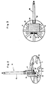
- the marker unit comprises a base . plate 7 having a plurality of reinforcing ribs 8, two pairs of holes 9 and a cut-out 10. Holes 9 serve for thread ing a plurality of units 5 by means of spikes to form a stack which is then charged into an apparatus according to the invention as will be explained further below.
- An arm 11 is pivoted at 12 to plate 7 and helical springs 13 bias the arm into the upright position shown in Fig. 2.
- Mounted on arm 11 are two markers: marker plate 14 which serves for daytime marking and a light stick 15 which serves for nighttime marking.
- Cut-out 10 serves for receiving the lower portion of light stick 15 in the folded state as shown in Fig. 3.
- FIG. 4 there is shown the manner in which an add-on apparatus 2 according to the invention is mounted on the rear of a battle tank 1 (see also Fig. 1).
- the rear of the battle tank 1 is fitted with an adaptor 17 comprising a plate 18 attached to the rear of tank 1, among other by chains 19, and comprising ribs 20 fitted with bearings 21.
- the apparatus 2 comprises two pivots 22 which are received by bearings 21 of adapter 17 and in this way the apparatus has a freedom of swinging in response to a bumpy terrain.
- Chains 23 serve as additional fastening means.
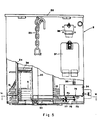
- the apparatus 2 comprises two vertical shafts 24 and 25 adapted each to hold a plurality of stacked folded marker units 5.
- the marker units in each stack are staggered so that each unit 5 of a stack is angularly displaced with respect to the two flanking units which latter are in turn overlapping.
- each stack is sub-divided into two groups staggered relative to each other, a first one comprising all even units and a second one comprising all uneven units with units in each group being overlapping and the two groups being angularly displaced towards each other as shown in Figs. 4 and 5.
- This arrangement is merely a matter of convenience which enables to maximize the number of marker units that can be accommodated in one single shaft.
- the upper wall 26 of apparatus 2 comprises openings 27 and 28 associated with shafts 24 and 25, respectively.
- Hole 27 is associated with radially extending cut-outs 29 and 30 and similarly hole 28 is associated with radially extending cut-outs 31 and 32, which cut-outs serve to admit the folded over light sticks 15 of the stacked marker units 5, the angle between each pair of cut-outs 29, 30 and 31, 32 corresponding to the angular displacement between the two groups in each stack.
- the units are first stacked outside the apparatus by threading them on suitably designed pikes (not shown) which engage the holes 9 and each ready formed stack is then introduced into one of the shafts whereupon the pikes are withdrawn.
- the apparatus 2 comprises a release mechanism 33 whose design will be explained below with reference to Figs. 6-9 and, associated therewith, an electric driving motor 34 connected by means of a cord 35 to a socket located behind a lid 36 which socket is electrically connectible to control means located inside the driver's cabin.
- a further lid 37 serves as closure for a compartment which serves for storing the electric harness of the apparatus when the latter is not mounted.
- each shaft when loaded holds a weight such as 38 which rests on the uppermost marker unit 5 of the stack and urges the unit towards the delivery gate.
- the apparatus 2 comprises a bottom piece 40 having two downward projecting sleeves 41 and 42 which are of the same diameter as and aligned with, respectively, shafts 24 and 25.
- Sleeves 41 and 42 serve as delivery gates.
- Sleeve 41 is fitted with two vertical slots 43 and likewise sleeve 42 is fitted with two vertical slots 44, slots 43 and 44 serving for the penetration of the projecting, folded light sticks 15 of marker units 5 (see also Fig. 5).
- Sleeves 41 and 42 further comprise horizontal slots 45 and 46 respectively, which serve for the penetration of the shears as will be described below.
- a slotted bracket 48 serving as guide for a slider-crank mechanism.
- a stud 49 which serves for mounting a pivot-and-hub assembly of the shears.
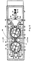
- the release mechanism further comprises an upper double shear 51 and a lower double shear 52.
- the upper double shear 51 comprises two shear legs 53 and 54 having, respectively, lugs 55 and 56, which lugs comprise holes and serve for pivoting.
- the lower double shear 52 comprises shear legs 57 and 58 fitted, respectively, with lugs 59 and 60, which lugs also have holes and serve for pivoting.
- Fig. 8 the distance between the end portions of the upper legs 53, 54 and the lower legs 57, 58 (only legs 53 and 57 being shown in Fig. 8.
- a sleeve 62 countersunk in stud 49 is held in position by means of a screw 63 whose threaded portion 64 engages a correspondingly threaded portion of the bore of stud 49, a washer 65 being interposed between the head of screw 63 and sleeve 62.
- the hole in lug 56 of shear leg 54 is of a size to fit directly on sleeve 62.
- the hole in lug 55 of shear leg 53 is of a larger size and fits into a circumferential, annular cut-out in the hub portion of lug 56 of shear leg 54.
- the hole in lug 59 of shear leg 57 fits directly on sleeve 62 while lug 60 of shear leg 58 fits into a circumferential, annular cut-out of the hub portion of lug 59 of shear leg 57.
- the shears are interlocked by means of protuberances 61 and 61 a integral with the hub portions of lugs 55 and 56 of the upper double shear 51 and received by correspondingly shaped recesses in the hub portions of lugs 59 and 60 of the lower double shear 52. Due to this interlock, when one shear portion of a double shear is converging the associated shear portion of the other double shear is spread and vice versa.
- the release mechanism further comprises a bottom plate 66 and a gasket 67.
- Bottom plate 66 comprises holes 68 and 71 and associated therewith branch-off cutouts 69, 70 and 71, 72, respectively.
- Holes 68 and 71 are matching in size with shafts 24 and 25 and the associated sleeves 41 and 42 and are in alignment therewith.
- Cut-outs 69, 70 and 71, 72 are designed to accommodate the folded-over light sticks 15, the angle between each two cutouts of a pair corresponding to the angular displacement between the two groups of marker units in a stack. In this way, once a marker unit is released it can drop freely through holes 68 or 71, as the case may be, and reach the ground as shown in Fig. 4.
- the release mechanism is driven by the electric motor 34 (see Fig. 5) via a slider-crank type transmission comprising a crank 74 having a horizontal arm 75 and a vertical pin 76, an intermediary link 77 and lateral links 79 and 80.
- Link 79 is pivoted at 81 to shear leg 53 and link 80 is pivoted at 82 to shear leg 54. Furthermore, links 79 and 80 are pivoted to each other by means of a pin 78 engaging the slot of bracket 48.
- the control of motor 34 is such that a rest period will follow each half revolution (180°) so that each cycle (360 ° ) will comprise two rest periods.
- the duration of such rest periods can be automatically correlated to the ground speed of the vehicle or be manually controlled.
- shear legs 53 and 54 of the upper double shear 51 comprise a pair of jaws 83 and 84 and near the opposite end of shear legs 53 and 54 there are provided jaws 85 and 86.
- the marker unit dispensing apparatus operates as follows:
- the light sticks 15c and 15d are activated by the actions of jaws 85 and 86 similarly as shown with respect to sticks 15a and 15b.
- the upper marker unit is blocked and retained in position by the converging shear legs 53 and 54 while the lower marker unit seen only by its light stick 15d is free to pass between the spread shear legs 57, 58 and drops on the ground.
- marker units 5 are dropped out altematingly and at controlled intervals from shaft 24 and 25 via sleeves 41 and 42 respectively, and in this way marker units 5 are strewn along the travel path of tank 1 as shown in Fig. 1.
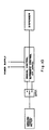
- the electric wiring for energizing apparatus 2 is shown diagrammatically in block diagrm of Fig. 10.
- a control device which can be switched between automatic and manual control and which is energized by a power supply within the tank.
- a ground travel meter whose readings are fed into the automatic control portion where they are adequately processed.
- the automatic control portion comprises a selector by means of which the distance at which the individual markers are to be dropped is selected.
- the motor in the dispenser is energized by electric pulses origina ting from the control and the duration of the rest period between one half revolution and another of the motor is determined by the control device.
Landscapes
- Engineering & Computer Science (AREA)
- Architecture (AREA)
- Civil Engineering (AREA)
- Structural Engineering (AREA)
- General Engineering & Computer Science (AREA)
- Automobile Manufacture Line, Endless Track Vehicle, Trailer (AREA)
- Automatic Assembly (AREA)
- Aiming, Guidance, Guns With A Light Source, Armor, Camouflage, And Targets (AREA)
- Road Signs Or Road Markings (AREA)
- Management, Administration, Business Operations System, And Electronic Commerce (AREA)
- Reduction Or Emphasis Of Bandwidth Of Signals (AREA)
- Networks Using Active Elements (AREA)
- Acyclic And Carbocyclic Compounds In Medicinal Compositions (AREA)
- Polishing Bodies And Polishing Tools (AREA)
- Fittings On The Vehicle Exterior For Carrying Loads, And Devices For Holding Or Mounting Articles (AREA)
- Guiding Agricultural Machines (AREA)
Claims (4)
Priority Applications (1)
| Application Number | Priority Date | Filing Date | Title |
|---|---|---|---|
| AT86109327T ATE43907T1 (de) | 1985-10-23 | 1986-07-08 | An einem landfahrzeug anzubringende vorrichtung zum legen von markierungszeichen. |
Applications Claiming Priority (2)
| Application Number | Priority Date | Filing Date | Title |
|---|---|---|---|
| IL76798 | 1985-10-23 | ||
| IL76798A IL76798A0 (en) | 1985-10-23 | 1985-10-23 | Apparatus for mounting on a land vehicle for the distribution of markers |
Publications (2)
| Publication Number | Publication Date |
|---|---|
| EP0226700A1 EP0226700A1 (de) | 1987-07-01 |
| EP0226700B1 true EP0226700B1 (de) | 1989-06-07 |
Family
ID=11056349
Family Applications (1)
| Application Number | Title | Priority Date | Filing Date |
|---|---|---|---|
| EP86109327A Expired EP0226700B1 (de) | 1985-10-23 | 1986-07-08 | An einem Landfahrzeug anzubringende Vorrichtung zum Legen von Markierungszeichen |
Country Status (11)
| Country | Link |
|---|---|
| US (1) | US4747515A (de) |
| EP (1) | EP0226700B1 (de) |
| JP (1) | JPS62119398A (de) |
| KR (1) | KR940010380B1 (de) |
| AT (1) | ATE43907T1 (de) |
| CA (1) | CA1265481A (de) |
| DE (1) | DE3663852D1 (de) |
| FI (1) | FI862866A7 (de) |
| IL (1) | IL76798A0 (de) |
| SG (1) | SG4590G (de) |
| ZA (1) | ZA865084B (de) |
Cited By (3)
| Publication number | Priority date | Publication date | Assignee | Title |
|---|---|---|---|---|
| EP0421198A1 (de) * | 1989-10-03 | 1991-04-10 | Alfred Dipl.-Ing. Ehrismann | Einrichtung an einem Fahrzeug zum Aufstellen von Absperrhüten |
| US5869967A (en) * | 1995-01-27 | 1999-02-09 | Lobbe Xenex Gmbh & Co. | Device for the detection of objects, especially explosive objects, lying in the earth |
| EP1134538A2 (de) | 2000-03-13 | 2001-09-19 | Rheinmetall Landsysteme GmbH | Markierelement mit einer Vorrichtung zum Verlegen gestapelter Markierelemente |
Families Citing this family (22)
| Publication number | Priority date | Publication date | Assignee | Title |
|---|---|---|---|---|
| US5054648A (en) * | 1990-01-23 | 1991-10-08 | Luoma Eugene H | Highway cone dispenser and collector |
| US5244334A (en) * | 1991-01-17 | 1993-09-14 | Shinmei Industry Co., Ltd. | Apparatus for installing and withdrawing road sign |
| FR2741897B1 (fr) * | 1995-12-04 | 1998-02-13 | Jean Jacques Meyer | Socle rabattable pour poteau de balisage |
| US20020046692A1 (en) * | 1996-10-30 | 2002-04-25 | Dan Pharo | Personnel guidance and location control system |
| US20020066400A1 (en) * | 1996-10-30 | 2002-06-06 | Dan Pharo | Personnel location control system with informational message presentation |
| US6259373B1 (en) | 1998-05-12 | 2001-07-10 | Bahador Ghahramani | Multiple hazard marker system, components therefor and methods of making the same |
| US6876308B1 (en) | 1998-05-12 | 2005-04-05 | Bahador Ghahramani | Intelligent system for detecting multiple hazards and field marker therefor |
| DE19942030A1 (de) * | 1999-09-03 | 2001-04-05 | Ffg Flensburger Fahrzeugbau Gm | Minenräumeinrichtung |
| CA2287033A1 (en) * | 1999-10-21 | 2001-04-21 | Geoid Exploration Ltd. | Land-marking device and a method of land surveying and marking |
| US20040149199A1 (en) * | 2003-01-15 | 2004-08-05 | Bae Systems Integrated Defense Solutions Inc. | Marking systems, methods and apparatuses |
| US7350328B1 (en) * | 2004-01-21 | 2008-04-01 | Traffix Devices, Inc. | Deployable traffic sign |
| US7108446B2 (en) * | 2004-03-09 | 2006-09-19 | Clark Brent A | Emergency warning device rapid deployment system |
| US7228813B2 (en) * | 2004-07-26 | 2007-06-12 | Angelo Lamar Flamingo | Traffic cone system |
| US7306398B2 (en) * | 2005-01-06 | 2007-12-11 | Doran Jr John Terrence | Highway marker transfer vehicle |
| US7444774B1 (en) | 2005-03-30 | 2008-11-04 | Traffix Devices, Inc. | Foldable traffic sign |
| US7571561B1 (en) | 2005-11-15 | 2009-08-11 | Worldwide Safety Of Nevada, Inc. | Deployable traffic sign |
| FR2943411B1 (fr) | 2009-03-19 | 2016-09-16 | Mbda France | Unite motorisee de deminage et de securisation d'un itineraire a risques. |
| US10319227B2 (en) | 2015-06-29 | 2019-06-11 | Royal Truck & Equipment, Inc. | Roadway work area safety truck |
| US10801169B2 (en) | 2015-06-29 | 2020-10-13 | Royal Truck & Equipment, Inc | Truck safety modules for assisting workpersons to place and retrieve traffic delineators |
| US11008717B2 (en) | 2015-06-29 | 2021-05-18 | Royal Truck & Equipment, Inc. | Safety truck attachments, and methods of safety truck use |
| US10556545B2 (en) | 2015-06-29 | 2020-02-11 | Royal Truck & Equipment, Inc. | Over-cab rack for traffic delineators |
| US12249255B1 (en) | 2023-09-13 | 2025-03-11 | Information Exchange Network, Inc. | Deployable portable sign system |
Family Cites Families (16)
| Publication number | Priority date | Publication date | Assignee | Title |
|---|---|---|---|---|
| US1162157A (en) * | 1914-04-16 | 1915-11-30 | American Can Co | Can-end-feed mechanism. |
| US1270923A (en) * | 1917-06-25 | 1918-07-02 | Sanitary Can Machinery Company | Can-cover-feeding device. |
| US1662298A (en) * | 1927-05-16 | 1928-03-13 | Samuel J Bialosky | Traffic signal |
| US2192635A (en) * | 1937-04-30 | 1940-03-05 | James G Bricker | Flag support |
| US2613463A (en) * | 1949-05-02 | 1952-10-14 | Edward S Transue | Portable road signal |
| US2980288A (en) * | 1956-04-09 | 1961-04-18 | Vendo Co | Mechanism for vending cylindrical containers disposed in staggered stack arrangement |
| US3478715A (en) * | 1969-02-25 | 1969-11-18 | Signal Lite Road Marker Co | Portable roadway signal device |
| US3756362A (en) * | 1970-11-09 | 1973-09-04 | Cornelius Co | Vending machine having sequential actuation of disperser |
| US3934539A (en) * | 1974-03-26 | 1976-01-27 | The United States Of America As Represented By The Secretary Of The Navy | Chemiluminescent foldable signal device |
| FI58187C (fi) * | 1976-10-26 | 1980-12-10 | Salon Automyynti Oy | Foerfarande foer faellning av varningsmaerken pao vaegyta eller motsvarande och anordning foer genomfoerande av foerfarandet |
| US4219141A (en) * | 1978-07-12 | 1980-08-26 | Lovy Robert L | Supporting frame for traffic cones on vehicles |
| GB2049767B (en) * | 1979-04-19 | 1983-02-16 | Warning Pyramids Ltd | Self-erecting road marker pyramid |
| GB8323079D0 (en) * | 1983-08-26 | 1983-09-28 | Solicitor For Affairs Of Her M | Collapsible hazard warning marker |
| US4552089A (en) * | 1983-10-14 | 1985-11-12 | Mahoney Thomas P | Road warning emergency system and method of utilizing same |
| FR2556378B1 (fr) * | 1983-12-13 | 1986-05-23 | Michit Emile | Procede et machine pour ramasser, stocker et poser mecaniquement des balises de signalisation routiere coniques et creuses |
| US4625893A (en) * | 1984-11-05 | 1986-12-02 | General Aero Products Corp. | Stamp booklet dispenser mechanism |
-
1985
- 1985-10-23 IL IL76798A patent/IL76798A0/xx not_active IP Right Cessation
-
1986
- 1986-07-07 FI FI862866A patent/FI862866A7/fi not_active Application Discontinuation
- 1986-07-08 AT AT86109327T patent/ATE43907T1/de not_active IP Right Cessation
- 1986-07-08 ZA ZA865084A patent/ZA865084B/xx unknown
- 1986-07-08 DE DE8686109327T patent/DE3663852D1/de not_active Expired
- 1986-07-08 EP EP86109327A patent/EP0226700B1/de not_active Expired
- 1986-07-09 US US06/883,735 patent/US4747515A/en not_active Expired - Fee Related
- 1986-07-21 CA CA514221A patent/CA1265481A/en not_active Expired - Fee Related
- 1986-07-31 KR KR1019860006288A patent/KR940010380B1/ko not_active Expired - Lifetime
- 1986-08-06 JP JP61184992A patent/JPS62119398A/ja active Pending
-
1990
- 1990-01-19 SG SG45/90A patent/SG4590G/en unknown
Cited By (6)
| Publication number | Priority date | Publication date | Assignee | Title |
|---|---|---|---|---|
| EP0421198A1 (de) * | 1989-10-03 | 1991-04-10 | Alfred Dipl.-Ing. Ehrismann | Einrichtung an einem Fahrzeug zum Aufstellen von Absperrhüten |
| CH679052A5 (de) * | 1989-10-03 | 1991-12-13 | Alfred Ehrismann Dipl Ing | |
| US5869967A (en) * | 1995-01-27 | 1999-02-09 | Lobbe Xenex Gmbh & Co. | Device for the detection of objects, especially explosive objects, lying in the earth |
| EP1134538A2 (de) | 2000-03-13 | 2001-09-19 | Rheinmetall Landsysteme GmbH | Markierelement mit einer Vorrichtung zum Verlegen gestapelter Markierelemente |
| DE10011748A1 (de) * | 2000-03-13 | 2001-10-04 | Rheinmetall W & M Gmbh | Markierelement mit einer Vorrichtung zum Verlegen gestapelter Markierelemente |
| DE10011748C2 (de) * | 2000-03-13 | 2002-09-12 | Rheinmetall W & M Gmbh | Markierelement und Vorrichtung zum Verlegen dieser Markierelemente |
Also Published As
| Publication number | Publication date |
|---|---|
| DE3663852D1 (en) | 1989-07-13 |
| FI862866A0 (fi) | 1986-07-07 |
| FI862866L (fi) | 1987-04-24 |
| FI862866A7 (fi) | 1987-04-24 |
| CA1265481A (en) | 1990-02-06 |
| IL76798A0 (en) | 1986-02-28 |
| KR870004288A (ko) | 1987-05-08 |
| EP0226700A1 (de) | 1987-07-01 |
| JPS62119398A (ja) | 1987-05-30 |
| US4747515A (en) | 1988-05-31 |
| SG4590G (en) | 1990-07-06 |
| ATE43907T1 (de) | 1989-06-15 |
| ZA865084B (en) | 1987-03-25 |
| KR940010380B1 (ko) | 1994-10-22 |
Similar Documents
| Publication | Publication Date | Title |
|---|---|---|
| EP0226700B1 (de) | An einem Landfahrzeug anzubringende Vorrichtung zum Legen von Markierungszeichen | |
| DE19502455C2 (de) | Vorrichtung zum Aufspüren von im Erdreich befindlichen Gegenständen, insbesondere explosiver Gegenstände | |
| DE112008001145B4 (de) | Spielzeugschienenset und Auslösesegmente | |
| EP1128152B1 (de) | An einem Kampffahrzeug angeordnete Wurfanlage für Nebelkerzen, Sprengkörper und dergleichen | |
| US20240229386A9 (en) | Road safety barrier installer, system and related methods | |
| DE102021100624A1 (de) | Anordnung zur Versorgung von Drohnen eines Drohnenschwarms | |
| DE2905422C2 (de) | Einrichtung zur Schußsimulation mit Trefferanzeige | |
| EP3973246A1 (de) | Vorrichtung und verfahren zum sprengen von lawinen | |
| WO1996023236A9 (de) | Vorrichtung zum aufspüren von im erdreich befindlichen gegenständen, insbesondere explosiver gegenstände | |
| DE2303404A1 (de) | Transportwagen fuer bewegliche zielobjekte auf schiessanlagen sowie damit ausgeruestete schiessanlage | |
| DE19619135A1 (de) | Unbemanntes gepanzertes Minenräumfahrzeug | |
| EP0022807A1 (de) | Verfahren und einrichtung zum künstlichen auslösen von lawinen | |
| DE2318055A1 (de) | Geraet zur raeumung von landminen | |
| US3470846A (en) | Marking the line of flight of an aircraft | |
| EP4179173A1 (de) | Verfahren zur verankerung von pfosten | |
| US4406230A (en) | Automatic conveyor system | |
| DE2656835A1 (de) | Verfahren zum verlegen einer schlauch leitung fuer loeschwasser | |
| DE4140662C1 (en) | Wildlife presence warning appts. - warns vehicle driver of presence of wildlife near road, or about to cross road, using ultrasound detectors near road-side | |
| EP1298409A1 (de) | Wurfsystem für einen Gefechtskopf mit einer Richtvorrichtung zur Neutralisierung von Minen | |
| WO2023247340A1 (de) | Verfahren und system zum anlernen einer fahrstrecke eines autonom fahrenden landwirtschaftlichen fahrroboters | |
| DE4022699A1 (de) | Vorrichtung zum selbsttaetigen maehen von rasenflaechen | |
| ATE39571T1 (de) | Geraet zum raeumen von auf einem untergrund verstreuten explosiven gegenstaenden. | |
| DE102020128888A1 (de) | Landwirtschaftliche Versorgungseinheit zum lösbaren Montieren an ein Fluggerät | |
| US20220030832A1 (en) | Vehicle, system and method for performing an animal-related action | |
| DE4041767A1 (de) | Mine mit einer verlegeeinrichtung fuer eine sensorleitung |
Legal Events
| Date | Code | Title | Description |
|---|---|---|---|
| PUAI | Public reference made under article 153(3) epc to a published international application that has entered the european phase |
Free format text: ORIGINAL CODE: 0009012 |
|
| AK | Designated contracting states |
Kind code of ref document: A1 Designated state(s): AT BE CH DE FR GB IT LI NL SE |
|
| 17P | Request for examination filed |
Effective date: 19870616 |
|
| 17Q | First examination report despatched |
Effective date: 19880303 |
|
| GRAA | (expected) grant |
Free format text: ORIGINAL CODE: 0009210 |
|
| AK | Designated contracting states |
Kind code of ref document: B1 Designated state(s): AT BE CH DE FR GB IT LI NL SE |
|
| REF | Corresponds to: |
Ref document number: 43907 Country of ref document: AT Date of ref document: 19890615 Kind code of ref document: T |
|
| REF | Corresponds to: |
Ref document number: 3663852 Country of ref document: DE Date of ref document: 19890713 |
|
| ITF | It: translation for a ep patent filed | ||
| ET | Fr: translation filed | ||
| PLBE | No opposition filed within time limit |
Free format text: ORIGINAL CODE: 0009261 |
|
| STAA | Information on the status of an ep patent application or granted ep patent |
Free format text: STATUS: NO OPPOSITION FILED WITHIN TIME LIMIT |
|
| 26N | No opposition filed | ||
| PGFP | Annual fee paid to national office [announced via postgrant information from national office to epo] |
Ref country code: AT Payment date: 19900713 Year of fee payment: 5 |
|
| PGFP | Annual fee paid to national office [announced via postgrant information from national office to epo] |
Ref country code: NL Payment date: 19900731 Year of fee payment: 5 |
|
| PGFP | Annual fee paid to national office [announced via postgrant information from national office to epo] |
Ref country code: BE Payment date: 19900808 Year of fee payment: 5 |
|
| PGFP | Annual fee paid to national office [announced via postgrant information from national office to epo] |
Ref country code: GB Payment date: 19910701 Year of fee payment: 6 |
|
| PG25 | Lapsed in a contracting state [announced via postgrant information from national office to epo] |
Ref country code: AT Effective date: 19910708 |
|
| PGFP | Annual fee paid to national office [announced via postgrant information from national office to epo] |
Ref country code: SE Payment date: 19910719 Year of fee payment: 6 |
|
| ITTA | It: last paid annual fee | ||
| PG25 | Lapsed in a contracting state [announced via postgrant information from national office to epo] |
Ref country code: BE Effective date: 19910731 |
|
| BERE | Be: lapsed |
Owner name: ISRAEL MILITARY INDUSTRIES Effective date: 19910731 Owner name: MINISTRY OF DEFENCE Effective date: 19910731 Owner name: THE STATE OF ISRAEL Effective date: 19910731 |
|
| PG25 | Lapsed in a contracting state [announced via postgrant information from national office to epo] |
Ref country code: NL Effective date: 19920201 |
|
| NLV4 | Nl: lapsed or anulled due to non-payment of the annual fee | ||
| PG25 | Lapsed in a contracting state [announced via postgrant information from national office to epo] |
Ref country code: GB Effective date: 19920708 |
|
| PG25 | Lapsed in a contracting state [announced via postgrant information from national office to epo] |
Ref country code: SE Effective date: 19920709 |
|
| GBPC | Gb: european patent ceased through non-payment of renewal fee |
Effective date: 19920708 |
|
| PGFP | Annual fee paid to national office [announced via postgrant information from national office to epo] |
Ref country code: DE Payment date: 19930823 Year of fee payment: 8 |
|
| PGFP | Annual fee paid to national office [announced via postgrant information from national office to epo] |
Ref country code: FR Payment date: 19930824 Year of fee payment: 8 |
|
| PGFP | Annual fee paid to national office [announced via postgrant information from national office to epo] |
Ref country code: CH Payment date: 19930825 Year of fee payment: 8 |
|
| PG25 | Lapsed in a contracting state [announced via postgrant information from national office to epo] |
Ref country code: LI Effective date: 19940731 Ref country code: CH Effective date: 19940731 |
|
| EUG | Se: european patent has lapsed |
Ref document number: 86109327.6 Effective date: 19930204 |
|
| PG25 | Lapsed in a contracting state [announced via postgrant information from national office to epo] |
Ref country code: FR Effective date: 19950331 |
|
| REG | Reference to a national code |
Ref country code: CH Ref legal event code: PL |
|
| PG25 | Lapsed in a contracting state [announced via postgrant information from national office to epo] |
Ref country code: DE Effective date: 19950401 |
|
| REG | Reference to a national code |
Ref country code: FR Ref legal event code: ST |
|
| PG25 | Lapsed in a contracting state [announced via postgrant information from national office to epo] |
Ref country code: IT Free format text: LAPSE BECAUSE OF NON-PAYMENT OF DUE FEES;WARNING: LAPSES OF ITALIAN PATENTS WITH EFFECTIVE DATE BEFORE 2007 MAY HAVE OCCURRED AT ANY TIME BEFORE 2007. THE CORRECT EFFECTIVE DATE MAY BE DIFFERENT FROM THE ONE RECORDED. Effective date: 20050708 |