EP0226706A1 - Verfahren zum Abdecken von Öffnungen auf einem Hohlkörper durch dünnwandige, flächenhafte Gebilde - Google Patents
Verfahren zum Abdecken von Öffnungen auf einem Hohlkörper durch dünnwandige, flächenhafte Gebilde Download PDFInfo
- Publication number
- EP0226706A1 EP0226706A1 EP86111866A EP86111866A EP0226706A1 EP 0226706 A1 EP0226706 A1 EP 0226706A1 EP 86111866 A EP86111866 A EP 86111866A EP 86111866 A EP86111866 A EP 86111866A EP 0226706 A1 EP0226706 A1 EP 0226706A1
- Authority
- EP
- European Patent Office
- Prior art keywords
- clamping plate
- openings
- film
- adhesive
- suction clamping
- Prior art date
- Legal status (The legal status is an assumption and is not a legal conclusion. Google has not performed a legal analysis and makes no representation as to the accuracy of the status listed.)
- Granted
Links
- 238000000034 method Methods 0.000 title claims abstract description 11
- 239000000463 material Substances 0.000 title claims abstract description 6
- 239000000853 adhesive Substances 0.000 claims abstract description 30
- 230000001070 adhesive effect Effects 0.000 claims abstract description 30
- 239000011324 bead Substances 0.000 claims abstract description 15
- 230000001413 cellular effect Effects 0.000 claims description 10
- 239000011888 foil Substances 0.000 claims description 5
- 238000004026 adhesive bonding Methods 0.000 claims description 2
- 239000010408 film Substances 0.000 description 36
- 238000011161 development Methods 0.000 description 4
- 238000003825 pressing Methods 0.000 description 4
- 238000004519 manufacturing process Methods 0.000 description 3
- 238000012360 testing method Methods 0.000 description 2
- 238000010521 absorption reaction Methods 0.000 description 1
- 239000002313 adhesive film Substances 0.000 description 1
- 229910052782 aluminium Inorganic materials 0.000 description 1
- XAGFODPZIPBFFR-UHFFFAOYSA-N aluminium Chemical compound [Al] XAGFODPZIPBFFR-UHFFFAOYSA-N 0.000 description 1
- 238000001816 cooling Methods 0.000 description 1
- 239000013039 cover film Substances 0.000 description 1
- 238000013461 design Methods 0.000 description 1
- 238000002474 experimental method Methods 0.000 description 1
- 239000006260 foam Substances 0.000 description 1
- 238000009413 insulation Methods 0.000 description 1
- 229910052751 metal Inorganic materials 0.000 description 1
- 239000002184 metal Substances 0.000 description 1
- 238000012806 monitoring device Methods 0.000 description 1
- 230000003287 optical effect Effects 0.000 description 1
- 239000004033 plastic Substances 0.000 description 1
- 230000035939 shock Effects 0.000 description 1
- 238000003860 storage Methods 0.000 description 1
- 239000000725 suspension Substances 0.000 description 1
- XLYOFNOQVPJJNP-UHFFFAOYSA-N water Substances O XLYOFNOQVPJJNP-UHFFFAOYSA-N 0.000 description 1
Images
Classifications
-
- B—PERFORMING OPERATIONS; TRANSPORTING
- B62—LAND VEHICLES FOR TRAVELLING OTHERWISE THAN ON RAILS
- B62D—MOTOR VEHICLES; TRAILERS
- B62D65/00—Designing, manufacturing, e.g. assembling, facilitating disassembly, or structurally modifying motor vehicles or trailers, not otherwise provided for
-
- B—PERFORMING OPERATIONS; TRANSPORTING
- B25—HAND TOOLS; PORTABLE POWER-DRIVEN TOOLS; MANIPULATORS
- B25J—MANIPULATORS; CHAMBERS PROVIDED WITH MANIPULATION DEVICES
- B25J15/00—Gripping heads and other end effectors
- B25J15/06—Gripping heads and other end effectors with vacuum or magnetic holding means
- B25J15/0616—Gripping heads and other end effectors with vacuum or magnetic holding means with vacuum
-
- B—PERFORMING OPERATIONS; TRANSPORTING
- B60—VEHICLES IN GENERAL
- B60R—VEHICLES, VEHICLE FITTINGS, OR VEHICLE PARTS, NOT OTHERWISE PROVIDED FOR
- B60R13/00—Elements for body-finishing, identifying, or decorating; Arrangements or adaptations for advertising purposes
- B60R13/02—Internal Trim mouldings ; Internal Ledges; Wall liners for passenger compartments; Roof liners
-
- B—PERFORMING OPERATIONS; TRANSPORTING
- B62—LAND VEHICLES FOR TRAVELLING OTHERWISE THAN ON RAILS
- B62D—MOTOR VEHICLES; TRAILERS
- B62D65/00—Designing, manufacturing, e.g. assembling, facilitating disassembly, or structurally modifying motor vehicles or trailers, not otherwise provided for
- B62D65/02—Joining sub-units or components to, or positioning sub-units or components with respect to, body shell or other sub-units or components
- B62D65/14—Joining sub-units or components to, or positioning sub-units or components with respect to, body shell or other sub-units or components the sub-units or components being passenger compartment fittings, e.g. seats, linings, trim, instrument panels
Definitions
- the invention relates to a method for covering openings according to the preamble of the first claim and to an apparatus for performing the method.
- openings are provided on the inside of motor vehicle doors in order to be able to install and remove the elements installed therein, for example windows and their guides, locks, etc. After the assembly of the individual components, these openings are sealed with a large-area film by applying adhesive to the door body on special contact surfaces. It is also known to use self-adhesive films. So far, this work has been done by hand, so it was very time-consuming.
- Films in the sense of this invention are also such thin-walled, flat structures which, in addition to a purely covering function, can also perform further functions, for example sound insulation and / or shock absorption. It is essential that they are attached by gluing and are foil-like, i.e. limp character.
- the object of the present invention is to avoid the disadvantages described above and to provide a method and an apparatus for carrying out the method with which these foils can be glued automatically. According to the invention, this object is achieved by the characterizing features of the first claim.
- the advantage of the solution is that with a single robot both the film can be taken from a stack of films and can be applied with a plastic material and then guided to the door to be glued. This will this step can be carried out in an extremely short time.
- the method is suitable for doors mounted on the vehicle body as well as for doors that can be assembled on separate production lines.
- the development according to claim 2 has the advantage that the expenditure on equipment can be reduced if the adhesive station is equipped with a fixedly equipped adhesive application nozzle. Since the robot is freely programmable anyway and has to transport the film from its storage location to the door, it is advantageous to have the traversing movement applied to the film to achieve one or more self-contained beads of adhesive.
- the development of the invention according to claim 4 has the advantage that no deformation occurs due to the rigid box when pressing the film. If this were to happen, the bead of adhesive would be too weakly pressed on the door edge and too strongly in the middle of the door.
- the provision of a large number of opening areas prevents the film from being drawn into the opening, as a result of which it can no longer be kept free of warpage.
- the development according to claim 5 prevents - since the film bulges slightly in the area of the openings due to the negative pressure - the film edge protrudes from the gripper.
- the multilayer structure of the work surface as described in claims 10 to 12, has the advantage that both unevenness in the door can be compensated for and a clean, edge-tight pressing of the adhesive bead can be achieved.
- the design according to the characterizing feature of claim 13 is preferred.
- the device according to the invention even with recessed adhesive surfaces, since the film and suction clamping plate are of the same size.
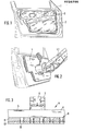
- a fully painted motor vehicle door 1 is shown from the inside.
- the openings on the inside are covered by a film 2 in a manner known per se.
- This film is glued to the inner sheet with the aid of an adhesive bead 3.
- a suction clamping plate 4 which is attached to a robot arm 4.1 (see FIG. 2).
- the suction clamping plate 4 has the dimensions of the film 2 to be glued. This has the advantage that the film can also be set back by means of the suction clamping plate 4, i.e. H. lower-lying surfaces can be glued on.
- the suction clamping plate 4 consists of a box 5, which is preferably made of aluminum sheets and profiles. The purpose of this box 5 is to be absolutely stiff against deformation. On the back 6 of the box 5, an opening 7 is provided, in which a suction fan 8 is arranged. This suction fan generates a negative pressure in box 5. Tests have shown that a negative pressure of about 20-100 mm water column is sufficient. Only a low-performance suction fan is required for this, so that there is no high energy requirement. This is advantageous because when the film is picked up, no cooling air is available for the suction fan.
- a plurality of rows of openings 10 are provided which are connected to the interior of the box 5.
- the rows of openings 10 are distributed over the entire front side 9 of the suction clamping plate 4, with the exception of the area in which the bead of adhesive is provided on the film.
- Tests have shown that it is sufficient to use the opening cross sections in the range between 10 and 20 mm, the opening with to choose a double opening cross-section, to arrange the individual rows offset from one another and to provide the row spacing in the range between 1.5 and 2 times the opening cross-section.
- No openings are provided in an area up to 20 mm from the edge of the suction plate so that the film does not protrude from the suction plate.
- the adjoining first two rows of openings have opening cross-sections smaller by about half.
- the cellular rubber mat 11 consists of medium-strength foam with a specific weight in the range of 0.3 g / cm 3 . It has a thickness in the range between 8 and 10 mm and thereby compensates for unevenness in the door and position inaccuracies as a result of parallelism errors between the inside of the door and the suction clamping plate 4.
- the cellular rubber mat 12 fastened thereon which comes into direct contact with the film 2, is soft compared to the cellular rubber mat 10 and has a specific weight in the range of 0.16 g / cm. It is primarily used for the clean, edge-tight pressing of the adhesive bead. Experiments have shown that a thickness of 2-3 mm is sufficient for the cellular rubber mat 12.
- the entire suction clamping plate 4 is connected to the robot arm 4.1 in a suitable manner.
- the connection point should be relatively soft to compensate for door position errors.
- the film is applied according to the invention in that the robot moves with the suction clamping plate 4 and the blower 8 switched off to a cut film stack. As soon as the suction clamping plate 4 with its cellular rubber mat 12 is positioned above the top film, the suction fan 8 is switched on. Here through the top film is attracted and held securely by the cellular rubber mat 10. The robot then moves with the suction clamping plate 4 and the picked-up film 2 to a fixedly arranged adhesive application station. This consists of a stationary adhesive application nozzle. As soon as the film is positioned in front of this nozzle, the nozzle is switched on and adhesive is applied to the film. The robot moves the film along a predetermined path past the adhesive discharge nozzle, so that the film is supplied with adhesive at all necessary points.
- the adhesive application nozzle is switched off and the robot moves the suction clamping plate 4, the film 2 and the applied adhesive bead 3 to the door 1.
- the suction clamping plate 4 is now exactly positioned here. This can be monitored using optical monitoring devices or buttons. Due to the cellular rubber mats and the soft suspension of the suction clamping plate 4 on the robot arm 5, small position errors of the door and unevenness in the sheet metal can be compensated for.
- the robot presses the suction clamping plate 4 against the inside of the door with a film and adhesive bead.
- the adhesive bead 3 comes into contact with the inner door panel, so that the film adheres.
- the suction fan 8 is switched off, so that the suction clamping plate 4 can be continued without the film 4.1 by the robot 4.1 to the film stack in order to be able to start a new fastening cycle.
Landscapes
- Engineering & Computer Science (AREA)
- Mechanical Engineering (AREA)
- Manufacturing & Machinery (AREA)
- Chemical & Material Sciences (AREA)
- Combustion & Propulsion (AREA)
- Transportation (AREA)
- Robotics (AREA)
- Automobile Manufacture Line, Endless Track Vehicle, Trailer (AREA)
Abstract
Description
- Die Erfindung bezieht sich auf ein Verfahren zum Abdecken von Öffnungen nach dem Gattungsbegriff des ersten Anspruchs sowie auf eine Vorrichtung zur Durchführung des Verfahrens.
- Es ist allgemein bekannt, daß in Kraftfahrzeugtüren auf deren Innenseite verschiedenartige Öffnungen vorgesehen sind, um die in ihr eingebauten Elemente, beispielsweise Fenster sowie deren Führung, Schlösser etc. ein und ausbauen zu können. Nach der Montage der einzelnen Bauteile werden diese Öffnungen durch eine großflächige Folie zugeklebt, indem auf speziellen Kontaktflächen auf dem Türkörper Klebstoff aufgebracht wird. Es ist auch bekannt, selbstklebende Folien zu verwenden. Diese Arbeiten wurden bisher von Hand durchgeführt, waren also sehr zeitintensiv.
- Folien im Sinne dieser Erfindung sind auch solche dünnwandigen, flächenhafte Gebilde, die neben einer reinen Abdeckfunktion noch weitere Funktionen, so zum Beispiel Schalldämmung und/oder Stoßabsorption, erfüllen können. Wesentlich ist, daß sie durch Kleben befestigt werden und folienähnlich sind, d.h. biegeschlaffen Charakter haben.
- Aufgabe der vorliegenden Erfindung ist es, die vorher beschriebenen Nachteile zu vermeiden und ein Verfahren und eine Vorrichtung zur Durchführung des Verfahrens bereitzustellen, mit dem diese Folien automatisch geklebt werden können. Diese Aufgabe wird erfindungsgemäß durch die kennzeichnenden Merkmale des ersten Anspruchs gelöst. Der Vorteil der Lösung besteht darin, daß mit einem einzigen Roboter sowohl die Folie von einem Folienstapel genommen als auch mit einem Kiebstoffauftrag versehen und sodann zu der zu beklebenden Tür geführt werden kann. Dadurch wird dieser Arbeitsschritt in äußerst kurzer Zeit durchführbar. Das Verfahren eignet sich sowohl für an der Fahrzeugkarosserie montierte Türen als auch für auf separaten Fertigungsstraßen komplettierbare Türen.
- Die Weiterbildung nach Anspruch 2 hat den Vorteil, daß der gerätetechnische Aufwand vermindert werden kann, wenn die Klebestation mit einer ortsfest ausgerüsteten Klebstoffauftragsdüse ausgerüstet ist. Da der Roboter sowieso frei programmierbar ist und die Folie von ihrem Lagerplatz zur Tür transportieren muß, ist es günstig, ihn auch die Verfahrbewegung zur Erzielung einer oder mehrerer in sich geschlossener Klebstoffraupen auf die Folie auftragen zu lassen.
- Eine zur Durchführung des Verfahrens geeignete Vorrichtung beschreiben die Ansprüche 3 bis 14. Zur Aufnahme der Folie und zu deren verwerfungsfreien Halten sowie Anbringen an der Türinnenseite hat sich eine mit geringem Unterdruck arbeitende Saugspannplatte als besonders geeignet herausgestellt.
- Die Weiterbildung der Erfindung nach Anspruch 4 hat den Vorteil, daß durch den formsteifen Kasten beim Anpressen der Folie keine Verformung auftritt. Würde dies nämlich geschehen, so würde die Klebstoffraupe am Türrand zu schwach und in der Türmitte zu stark angedrückt. Durch das Vorsehen von einer Vielzahl von Öffnungsreichen wird verhindert, daß die Folie in die Öffnung hineingezogen wird, wodurch sie nicht mehr verwerfungsfrei gehalten werden kann.
- Durch die Weiterbildung nach Anspruch 5 wird verhindert, daß - da die Folie durch den Unterdruck sich im Bereich der Öffnungen leicht wölbt - der Folienrand vom Greifer absteht.
- Durch die Anordnung nach den kennzeichnenden Merkmalen der Ansprüche 7 und 8 wird eine möglichst große Saugfläche erzielt, um die Folie festzuhalten, ohne die Planlage zu gefährden. Durch die Weiterbildung nach Anspruch 9 wird sichergestellt, daß überall dort, wo die Klebstoffraupe vorgesehen ist, auch ein Anpreßdruck ausgeübt werden kann.
- Durch den mehrschichtigen Aufbau der Arbeitsfläche, wie er in den Ansprüchen 10 bis 12 beschrieben wird, wird der Vorteil erreicht, daß sowohl Unebenheiten in der Tür ausgeglichen werden können, als auch ein sauberes, randscharfes Anpressen der Klebstoffraupe erzielt werden kann.
- Für die Saugspannplattenaußenkontur wird bevorzugt die Ausbildung nach dem kennzeichnenden Merkmal des Anspruchs 13. Dadurch ist es weiterhin möglich, die erfindungsgemäße Vorrichtung auch bei zurückgesetzten Klebeflächen zu verwenden, da Folie und Saugspannplatte gleich groß sind.
- Um flexibel in der Fertigung zu sein, ist es sinnvoll, die Saugspannplatte auswechselbar an dem Roboter zu befestigen. Dadurch können auf einer Fertigungsstraße Türen unterschiedlicher Größe alleine durch Auswechseln des Saugspannrahmens bearbeitet werden (Anspruch 14).
- Im folgenden wird die Erfindung anhand eines bevorzugten Ausführungsbeispiels näher dargestellt. Es stellen dar:
- Fig. 1 die Innenseite einer Kraftfahrzeugtür mit montierter Abdeckfolie;
- Fig. 2 eine perspektifische Darstellung einer Kraftfahrzeugtür, an der gerade die Folie mit Hilfe des Saugspannrahmens angeklebt wird;
- Fig. 3 einen Querschnitt durch die erfindungsgemäß aufgebaute Saugspannplatte.
- In Fig. 1 ist eine fertig lackierte Kraftfahrzeugtür 1 von deren Innenseite her dargestellt. Die auf der Innenseite liegenden Öffnungen werden in an sich bekannter Weise durch eine Folie 2 überdeckt. Diese Folie wird mit Hilfe einer Klebstoffraupe 3 auf das Innenblech geklebt.
- Erfindungsgemäß wird dies mit Hilfe einer Saugspannplatte 4, die an einem Roboterarm 4.1 befestigt ist, bewerkstelligt (siehe Fig. 2). Die Saugspannplatte 4 hat hierbei die Abmessungen der zu klebenden Folie 2. Dies hat den Vorteil, daß die Folie mit Hilfe der Saugspannplatte 4 auch auf zurückversetzte, d. h. tieferliegende Flächen aufgeklebt werden kann.
- Fig. 3 zeigt einen Querschnitt durch die erfindungsgemäß aufgebaute Saugspannplatte 4. Die Saugspannplatte 4 besteht aus einem Kasten 5, welcher bevorzugt aus Aluminiumblechen und Profilen hergestellt ist. Aufgabe dieses Kastens 5 ist es, absolut steif gegenüber Verformungen zu sein. Auf der Rückseite 6 des Kastens 5 ist eine Öffnung 7 vorgesehen, in welcher ein Sauglüfter 8 angeordnet ist. Dieser Sauglüfter erzeugt im Kasten 5 einen Unterdruck. Versuche haben ergeben, daß ein Unterdruck von ca. 20 - 100 mm Wassersäule ausreichend ist. Hierzu ist nur ein leistungsschwacher Sauglüfter erforderlich, so daß kein hoher Energiebedarf besteht. Dies ist vorteilhaft, weil bei aufgenommener Folie keine Kühlluft für den Sauglüfter zur Verfügung steht.
- Auf der Vorderseite 9 des Kastens 5 sind eine Vielzahl von Öffnungsreihen 10 vorgesehen, die mit dem Inneren des Kastens 5 in Verbindung stehen. Die Öffnungsreihen 10 sind auf der gesamten Vorderseite 9 der Saugspannplatte 4 verteilt, mit Ausnahme des Bereiches, in dem die Kleberaupe auf der Folie vorgesehen ist. Versuche haben ergeben, daß es ausreichend ist, die Öffnungsquerschnitte im Bereich zwischen 10 und 20 mm, den Öffnungsmittenabstand auf doppelten Öffnungsquerschnitt zu wählen, die einzelnen Reihen versetzt untereinander anzuordnen und den Reihenabstand im Bereich zwischen dem 1,5 bis 2-fachen Öffnungsquerschnitt vorzusehen. In einem Bereich bis zu 20 mm vom Saugspannplattenrand sind keine Öffnungen vorgesehen, damit die Folie nicht von der Saugspannplatte absteht. Die sich daran anschließenden ersten beiden Öffnungsreihen weisen um etwa die Hälfte kleinere Öffnungsquerschnitte auf.
- Zum Ausgleich von Unebenheiten im Türinnenblech sowie zum sauberen, randscharfen Anpressen der Klebstoffraupe sind auf der Vorderseite 9 des Kastens 5 zwei unterschiedlich harte Zellgummimatten 11 und 12 aufgebracht. Die Zellgummimatte 11 besteht aus mittelfestem Schaum mit einem spezifischen Gewicht im Bereich vom 0,3 g/cm3. Sie weist eine Stärke im Bereich zwischen 8 und 10 mm auf und gleicht dadurch Unebenheiten in der Tür sowie Positionsungenauigkeiten infolge Parallelitätsfehler zwischen Türinnenseite und Saugspannplatte 4 aus. Die darauf befestigte Zellgummimatte 12, die direkt mit der Folie 2 in Kontakt gelangt, ist gegenüber der Zellgummimatte 10 weich und weist ein spezifisches Gewicht im Bereich von 0,16 g/cm auf. Sie dient in erster Linie zum sauberen, randscharfen Anpressen der Klebstoffraupe. Versuche haben ergeben, daß eine Stärke von 2 - 3 mm für die Zellgummimatte 12 ausreichend ist.
- Die gesamte Saugspannplatte 4 ist mit dem Roboterarm 4.1 in geeigneter Weise verbunden. Die Verbindungsstelle sollte jedoch relativ weich sein, um Lagefehler der Tür auszugleichen.
- Das Aufbringen der Folie geschieht erfindungsgemäß dadurch, daß der Roboter mit der Saugspannplatte 4 und ausgeschaltetem Gebläse 8 zu einem zugeschnittenen Folienstapel fährt. Sobald die Saugspannplatte 4 mit ihrer Zellgummimatte 12 oberhalb der obersten Folie positioniert ist, wird der Sauglüfter 8 eingeschaltet. Hierdurch wird die oberste Folie angezogen und sicher von der Zellgummimatte 10 gehalten. Sodann verfährt der Roboter mit der Saugspannplatte 4 und der aufgenommenen Folie 2 zu einer ortsfest angeordneten Klebstoffauftragsstation. Diese besteht aus einer ortsfest angeordneten Klebstoffauftragsdüse. Sobald die Folie vor dieser Düse positioniert ist, wird die Düse eingeschaltet und Klebstoff auf die Folie aufgetragen. Dabei bewegt der Roboter die Folie entlang eines vorgegebenen Weges an der Klebstoffaustragsdüse vorbei, so daß die Folie an allen notwendigen Stellen mit Klebstoff versorgt wird.
- Nachdem dies geschehen ist, wird die Klebstoffauftragsdüse abgeschaltet und der Roboter verfährt die Saugspannplatte 4, die Folie 2 und der aufgetragenen Klebstoffraupe 3 zur Tür 1. Hier wird nun die Saugspannplatte 4 exakt positioniert. Dies kann mit Hilfe von optischen Überwachungsgeräten oder Tastern überwacht werden. Aufgrund der Zellgummimatten sowie der weichen Aufhängung der Saugspannplatte 4 an dem Roboterarm 5 können kleine Lagefehler der Tür sowie Blechunebenheiten ausgeglichen werden.
- Sobald die Saugspannplatte 4 ordnungsgemäß positioniert ist, drückt der Roboter die Saugspannplatte 4 mit Folie und Klebstoffraupe gegen die Türinnenseite. Dadurch gelangt die Klebstoffraupe 3 mit dem Türinnenblech in Kontakt, so daß die Folie haftet. Sodann wird der Sauglüfter 8 ausgeschaltet, so daß die Saugspannplatte 4 ohne Folie wieder von dem Roboter 4.1 fortgefahren werden kann zu dem Folienstapel, um einen neuen Befestigungszyklus beginnen zu können.
Claims (14)
dadurch gekennzeichnet, daß die Klebauftragstation aus einer ortsfesten angebrachten Klebstoffauftragsdüse besteht, an welcher die Folie zum Auftragen der Klebstoffraupe entlang geführt wird.
dadurch gekennzeichnet, daß eine mit Unterdruck arbeitende Saugspannplatte (4) an einem Arm (4.1) eines Roboters vorgesehen ist.
dadurch gekennzeichnet, daß die Saugspannplatte (4) aus einem formsteifen Kasten (5) mit nachgiebiger Arbeitsfläche besteht, wobei die Arbeitsfläche eine Vielzahl von mit einer Unterdruckquelle (Sauglüfter 9) in Verbindung stehenden Öffnungsreihen (10) aufweist.
dadurch gekennzeichnet, daß im Randbereich die Saugspannplatte keine Öffnungen vorgesehen sind.
dadurch gekennzeichnet, daß der Öffnungsabstand in einer Reihe dem doppelten Öffnungsquerschnitt entspricht.
dadurch gekennzeichnet, daß der Abstand der einzelnen Öffnungsreihen im Bereich von 1,5 - 2fachen des Öffnungsquerschnitts liegt.
dadurch gekennzeichnet, daß die Öffnungen nur im nicht mit den Kleberaupen in Kontakt gelangenden Folienbereich vorgesehen sind.
dadurch gekennzeichnet, daß die Arbeitsfläche mehrschichtig aufgebaut ist.
dadurch gekennzeichnet, daß die mit der Folie (2) in Kontakt gelangende erste Schicht (12) der Arbeitsfläche aus einer weichen Matte nachgiebigen Materials besteht, die auf einer zweiten Schicht (11) aus einer mittelfesten Matte nachgiebigen Matrials aufgebracht ist, die wiederum an dem Kasten (5) befestigt ist.
dadurch gekennzeichnet, daß die erste Schicht (12) aus Zellgummit mit einem spezifischen Gewicht im Bereich von 0,16 g/cm und die zweite Schicht (11) ebenfalls aus Zellgummi mit einem spezifischen Gewicht im Bereich von 0,3 g/cm besteht.
dadurch gekennzeichnet, daß die Kontur der Saugspannplatte (4) der Kontur der Folie (2) angepaßt ist.
dadurch gekennzeichnet, daß die Saugspannplatte (4) auswechselbar an dem Roboterarm (4.1) befestigt ist.
Applications Claiming Priority (2)
| Application Number | Priority Date | Filing Date | Title |
|---|---|---|---|
| DE19853531243 DE3531243A1 (de) | 1985-08-31 | 1985-08-31 | Verfahren zum abdecken von oeffnungen auf einem hohlkoerper |
| DE3531243 | 1985-08-31 |
Publications (3)
| Publication Number | Publication Date |
|---|---|
| EP0226706A1 true EP0226706A1 (de) | 1987-07-01 |
| EP0226706B1 EP0226706B1 (de) | 1989-03-15 |
| EP0226706B2 EP0226706B2 (de) | 1995-06-21 |
Family
ID=6279904
Family Applications (1)
| Application Number | Title | Priority Date | Filing Date |
|---|---|---|---|
| EP19860111866 Expired - Lifetime EP0226706B2 (de) | 1985-08-31 | 1986-08-27 | Verfahren zum Abdecken von Öffnungen auf einem Hohlkörper durch dünnwandige, flächenhafte Gebilde |
Country Status (2)
| Country | Link |
|---|---|
| EP (1) | EP0226706B2 (de) |
| DE (2) | DE3531243A1 (de) |
Cited By (4)
| Publication number | Priority date | Publication date | Assignee | Title |
|---|---|---|---|---|
| WO2001062447A1 (de) * | 2000-02-26 | 2001-08-30 | J. Schmalz Gmbh | Handhabungsgerät, insbesondere vakuumhandhabungsgerät |
| FR2839022A1 (fr) * | 2002-04-30 | 2003-10-31 | Sofitec Sa | Panneau d'etancheite, en particulier pour porte de vehicule automobile, et ses moyens de fabrication |
| EP1477396A1 (de) * | 2003-05-12 | 2004-11-17 | Peugeot Citroen Automobiles S.A. | Verfahren und Werkzeug für den Einbau eines Feuchtschutzes in einer Kraftfahrzeug-Tür |
| WO2004113106A1 (fr) * | 2003-06-20 | 2004-12-29 | Peugeot Citroen Automobiles | Procede et dispositif de mise en pression d'une feuille d'etancheite sur un element de carrosserie |
Families Citing this family (8)
| Publication number | Priority date | Publication date | Assignee | Title |
|---|---|---|---|---|
| DE4034291C3 (de) * | 1990-10-27 | 1999-07-29 | Bayerische Motoren Werke Ag | Verfahren zum Auftragen einer Kleberraupe auf einen Flachkörper mittels eines Roboters |
| DE19717760B4 (de) * | 1997-04-22 | 2004-01-22 | Brose Fahrzeugteile Gmbh & Co. Kg, Coburg | Fahrzeugtür mit einer Naß-/Trockenraumtrennung |
| DE29712202U1 (de) * | 1997-07-11 | 1998-08-20 | KUKA Schweissanlagen GmbH, 86165 Augsburg | Einbauanlage für Fahrzeugteile |
| DE10304487B4 (de) * | 2003-02-05 | 2008-09-25 | Audi Ag | Anpressvorrichtung zum Verpressen einer Kleberaupe |
| FR2923170B1 (fr) * | 2007-11-07 | 2010-04-09 | Peugeot Citroen Automobiles Sa | Outil de mise en pression d'un cordon de produit adhesif. |
| DE102008007382A1 (de) * | 2008-02-01 | 2009-08-13 | Kuka Innotec Gmbh | Verfahren und Vorrichtung zum Positionieren eines Werkzeugs an einem Werkstück einer Scheibe in ein Kraftfahrzeug |
| FR3081114B1 (fr) * | 2018-05-17 | 2020-04-17 | Psa Automobiles Sa | Dispositif de positionnement d’une plaque sur une piece de tolerie |
| US12420879B1 (en) * | 2024-05-29 | 2025-09-23 | Tesla, Inc. | Automated exterior vehicle part assembly using global datum |
Citations (2)
| Publication number | Priority date | Publication date | Assignee | Title |
|---|---|---|---|---|
| FR2284470A1 (fr) * | 1974-09-13 | 1976-04-09 | Johnson Matthey Co Ltd | Dispositif a depression pour manipulation de decalcomanies |
| DE2941209A1 (de) * | 1979-10-11 | 1981-04-23 | Volkswagenwerk Ag, 3180 Wolfsburg | Verfahren zur befestigung einer abdichtfolie auf dem innenblech einer fahrzeugtuer |
Family Cites Families (1)
| Publication number | Priority date | Publication date | Assignee | Title |
|---|---|---|---|---|
| DE3342570C2 (de) * | 1983-11-25 | 1986-07-10 | Thyssen Maschinenbau GmbH Nothelfer-Ravensburg, 7980 Ravensburg | Verfahren zum Befestigen einer Tür an einer Karosserie eines Kraftfahrzeuges und Vorrichtung zum Durchführen dieses Verfahrens |
-
1985
- 1985-08-31 DE DE19853531243 patent/DE3531243A1/de active Granted
-
1986
- 1986-08-27 EP EP19860111866 patent/EP0226706B2/de not_active Expired - Lifetime
- 1986-08-27 DE DE8686111866T patent/DE3662367D1/de not_active Expired
Patent Citations (2)
| Publication number | Priority date | Publication date | Assignee | Title |
|---|---|---|---|---|
| FR2284470A1 (fr) * | 1974-09-13 | 1976-04-09 | Johnson Matthey Co Ltd | Dispositif a depression pour manipulation de decalcomanies |
| DE2941209A1 (de) * | 1979-10-11 | 1981-04-23 | Volkswagenwerk Ag, 3180 Wolfsburg | Verfahren zur befestigung einer abdichtfolie auf dem innenblech einer fahrzeugtuer |
Cited By (6)
| Publication number | Priority date | Publication date | Assignee | Title |
|---|---|---|---|---|
| WO2001062447A1 (de) * | 2000-02-26 | 2001-08-30 | J. Schmalz Gmbh | Handhabungsgerät, insbesondere vakuumhandhabungsgerät |
| FR2839022A1 (fr) * | 2002-04-30 | 2003-10-31 | Sofitec Sa | Panneau d'etancheite, en particulier pour porte de vehicule automobile, et ses moyens de fabrication |
| WO2003093063A1 (fr) * | 2002-04-30 | 2003-11-13 | Sofitec Sa | Panneau d'etancheite, en particulier pour porte de vehicule automobile, et procede et ses moyens de fabrication |
| EP1477396A1 (de) * | 2003-05-12 | 2004-11-17 | Peugeot Citroen Automobiles S.A. | Verfahren und Werkzeug für den Einbau eines Feuchtschutzes in einer Kraftfahrzeug-Tür |
| FR2854863A1 (fr) * | 2003-05-12 | 2004-11-19 | Peugeot Citroen Automobiles Sa | Procede et dispositif de pose d'une feuille d'etancheite d'une porte de vehicule automobile |
| WO2004113106A1 (fr) * | 2003-06-20 | 2004-12-29 | Peugeot Citroen Automobiles | Procede et dispositif de mise en pression d'une feuille d'etancheite sur un element de carrosserie |
Also Published As
| Publication number | Publication date |
|---|---|
| EP0226706B1 (de) | 1989-03-15 |
| DE3662367D1 (en) | 1989-04-20 |
| EP0226706B2 (de) | 1995-06-21 |
| DE3531243C2 (de) | 1989-04-27 |
| DE3531243A1 (de) | 1987-03-12 |
Similar Documents
| Publication | Publication Date | Title |
|---|---|---|
| DE69019170T2 (de) | Vorgeschlitzte Injektionsstelle sowie konische Kanüle. | |
| EP0226706B1 (de) | Verfahren zum Abdecken von Öffnungen auf einem Hohlkörper durch dünnwandige, flächenhafte Gebilde | |
| DE2905841C2 (de) | Verfahren und Anlage zur Herstellung einer Verbundplatte | |
| EP1257389B1 (de) | Vakuumhandhabungsgerät | |
| DE3345626A1 (de) | Verfahren und vorrichtung zum herstellen eines kaschierten formteils | |
| DE102022119561A1 (de) | Vorrichtung und Verfahren zum Herstellen von Taschenfederkernmatratzen | |
| DE3634357C2 (de) | Vorrichtung zur Vakuumkompression eines Laminats | |
| EP0297422B1 (de) | Vorrichtung zur elektrostatischen Sprühbeschichtung von plattenförmigen Werkstücken | |
| EP0163255B1 (de) | Vorrichtung zum automatischen Beschicken einer Laminierstation | |
| DE3334009C2 (de) | Vorrichtung zum Laminieren eines Folienstückes auf einen plattenförmigen Gegenstand | |
| DE3808443A1 (de) | Verfahren und vorrichtung zum ankleben von biegeschlaffen strangartigen profilen | |
| DE68918823T2 (de) | Vorrichtung zum Ausschneiden von Tab-Anordnungen und zum Formen von deren Anschlüssen. | |
| EP2217516A1 (de) | Vorrichtung zum pneumatischen aufnehmen eines flächigen gegenstands | |
| DE60103891T2 (de) | Verbundene profile, vorrichtung und verfahren zum verbinden von profilen | |
| DE4424845C2 (de) | Abdeckplatte für Vakuumformmaschinen | |
| DE69020170T4 (de) | Apparat zum beschichten der oberfläche und der seitenkanten einer platte aus holz oder ähnlichem material mit einer wärmeverformbaren folie. | |
| DE2820630A1 (de) | Verfahren und vorrichtung zum zusammenstellen von isolierglaselementen | |
| EP2822752A1 (de) | Strahlgestützte fügemaschine, insbesondere laser-durchstrahl-schweisseinrichtung | |
| DE3025829A1 (de) | Schutzvorrichtung zum schuetzen einer projektionsmaske fuer einen projektor | |
| DE69102011T2 (de) | Universales bewegliches Oberwerkzeug zum Entfernen des Abfalles in einer Blattschneidemaschine zur Herstellung von Verpackungsmaterial. | |
| WO1997002723A1 (de) | Verfahren und vorrichtung zur verbindung von mit wärmequellen versehenen platten, insbesondere elektrischen leiterplatten, mit metallischen wärmeableitplatten | |
| DE102014201706A1 (de) | Vorrichtung und Verfahren zum Applizieren einer Folie auf ein Fahrzeugteil | |
| EP0532829B1 (de) | Flächiger Gegenstand mit Wabenstruktur | |
| WO2008067580A1 (de) | Verfahren sowie vorrichtung zum positionieren von einem glaselement und einer kunststofffolie aufeinander | |
| EP0426065B1 (de) | Biegemaschine |
Legal Events
| Date | Code | Title | Description |
|---|---|---|---|
| PUAI | Public reference made under article 153(3) epc to a published international application that has entered the european phase |
Free format text: ORIGINAL CODE: 0009012 |
|
| AK | Designated contracting states |
Kind code of ref document: A1 Designated state(s): DE FR GB IT SE |
|
| 17P | Request for examination filed |
Effective date: 19870508 |
|
| 17Q | First examination report despatched |
Effective date: 19880822 |
|
| GRAA | (expected) grant |
Free format text: ORIGINAL CODE: 0009210 |
|
| AK | Designated contracting states |
Kind code of ref document: B1 Designated state(s): DE FR GB IT SE |
|
| REF | Corresponds to: |
Ref document number: 3662367 Country of ref document: DE Date of ref document: 19890420 |
|
| ET | Fr: translation filed | ||
| ITF | It: translation for a ep patent filed | ||
| GBT | Gb: translation of ep patent filed (gb section 77(6)(a)/1977) | ||
| PLBI | Opposition filed |
Free format text: ORIGINAL CODE: 0009260 |
|
| 26 | Opposition filed |
Opponent name: KUKA SCHWEISSANLAGEN + ROBOTER GMBH Effective date: 19891214 |
|
| ITTA | It: last paid annual fee | ||
| RAP4 | Party data changed (patent owner data changed or rights of a patent transferred) |
Owner name: BAYERISCHE MOTOREN WERKE AKTIENGESELLSCHAFT |
|
| EAL | Se: european patent in force in sweden |
Ref document number: 86111866.9 |
|
| PUAH | Patent maintained in amended form |
Free format text: ORIGINAL CODE: 0009272 |
|
| STAA | Information on the status of an ep patent application or granted ep patent |
Free format text: STATUS: PATENT MAINTAINED AS AMENDED |
|
| 27A | Patent maintained in amended form |
Effective date: 19950621 |
|
| AK | Designated contracting states |
Kind code of ref document: B2 Designated state(s): DE FR GB IT SE |
|
| ET3 | Fr: translation filed ** decision concerning opposition | ||
| GBTA | Gb: translation of amended ep patent filed (gb section 77(6)(b)/1977) |
Effective date: 19950628 |
|
| ITF | It: translation for a ep patent filed | ||
| PGFP | Annual fee paid to national office [announced via postgrant information from national office to epo] |
Ref country code: SE Payment date: 19960717 Year of fee payment: 11 |
|
| PGFP | Annual fee paid to national office [announced via postgrant information from national office to epo] |
Ref country code: GB Payment date: 19960822 Year of fee payment: 11 |
|
| PGFP | Annual fee paid to national office [announced via postgrant information from national office to epo] |
Ref country code: FR Payment date: 19960830 Year of fee payment: 11 |
|
| APAC | Appeal dossier modified |
Free format text: ORIGINAL CODE: EPIDOS NOAPO |
|
| APAC | Appeal dossier modified |
Free format text: ORIGINAL CODE: EPIDOS NOAPO |
|
| PG25 | Lapsed in a contracting state [announced via postgrant information from national office to epo] |
Ref country code: GB Free format text: LAPSE BECAUSE OF NON-PAYMENT OF DUE FEES Effective date: 19970827 |
|
| PG25 | Lapsed in a contracting state [announced via postgrant information from national office to epo] |
Ref country code: SE Free format text: LAPSE BECAUSE OF NON-PAYMENT OF DUE FEES Effective date: 19970828 |
|
| PGFP | Annual fee paid to national office [announced via postgrant information from national office to epo] |
Ref country code: DE Payment date: 19970910 Year of fee payment: 12 |
|
| GBPC | Gb: european patent ceased through non-payment of renewal fee |
Effective date: 19970827 |
|
| PG25 | Lapsed in a contracting state [announced via postgrant information from national office to epo] |
Ref country code: FR Free format text: LAPSE BECAUSE OF NON-PAYMENT OF DUE FEES Effective date: 19980430 |
|
| EUG | Se: european patent has lapsed |
Ref document number: 86111866.9 |
|
| REG | Reference to a national code |
Ref country code: FR Ref legal event code: ST |
|
| PG25 | Lapsed in a contracting state [announced via postgrant information from national office to epo] |
Ref country code: DE Free format text: LAPSE BECAUSE OF NON-PAYMENT OF DUE FEES Effective date: 19990601 |
|
| PG25 | Lapsed in a contracting state [announced via postgrant information from national office to epo] |
Ref country code: IT Free format text: LAPSE BECAUSE OF NON-PAYMENT OF DUE FEES;WARNING: LAPSES OF ITALIAN PATENTS WITH EFFECTIVE DATE BEFORE 2007 MAY HAVE OCCURRED AT ANY TIME BEFORE 2007. THE CORRECT EFFECTIVE DATE MAY BE DIFFERENT FROM THE ONE RECORDED. Effective date: 20050827 |
|
| APAH | Appeal reference modified |
Free format text: ORIGINAL CODE: EPIDOSCREFNO |