EP0226742A2 - Capteur de pression pour mesurer des pressions à hautes températures - Google Patents
Capteur de pression pour mesurer des pressions à hautes températures Download PDFInfo
- Publication number
- EP0226742A2 EP0226742A2 EP86114305A EP86114305A EP0226742A2 EP 0226742 A2 EP0226742 A2 EP 0226742A2 EP 86114305 A EP86114305 A EP 86114305A EP 86114305 A EP86114305 A EP 86114305A EP 0226742 A2 EP0226742 A2 EP 0226742A2
- Authority
- EP
- European Patent Office
- Prior art keywords
- pressure sensor
- sensor according
- piezoelectric element
- force
- pressure
- Prior art date
- Legal status (The legal status is an assumption and is not a legal conclusion. Google has not performed a legal analysis and makes no representation as to the accuracy of the status listed.)
- Granted
Links
- 238000002485 combustion reaction Methods 0.000 claims abstract description 28
- 238000009530 blood pressure measurement Methods 0.000 claims abstract description 5
- 239000013078 crystal Substances 0.000 claims description 31
- 230000000694 effects Effects 0.000 claims description 18
- 239000000463 material Substances 0.000 claims description 7
- GQYHUHYESMUTHG-UHFFFAOYSA-N lithium niobate Chemical compound [Li+].[O-][Nb](=O)=O GQYHUHYESMUTHG-UHFFFAOYSA-N 0.000 claims description 5
- 238000000034 method Methods 0.000 claims description 4
- 230000008569 process Effects 0.000 claims description 4
- 238000006243 chemical reaction Methods 0.000 claims description 3
- 239000010408 film Substances 0.000 claims description 3
- WSMQKESQZFQMFW-UHFFFAOYSA-N 5-methyl-pyrazole-3-carboxylic acid Chemical compound CC1=CC(C(O)=O)=NN1 WSMQKESQZFQMFW-UHFFFAOYSA-N 0.000 claims description 2
- 229910010293 ceramic material Inorganic materials 0.000 claims description 2
- 238000009826 distribution Methods 0.000 claims description 2
- 238000004544 sputter deposition Methods 0.000 claims description 2
- 239000010409 thin film Substances 0.000 claims description 2
- 239000011032 tourmaline Substances 0.000 claims description 2
- 229940070527 tourmaline Drugs 0.000 claims description 2
- 229910052613 tourmaline Inorganic materials 0.000 claims description 2
- 238000007740 vapor deposition Methods 0.000 claims description 2
- VYPSYNLAJGMNEJ-UHFFFAOYSA-N silicon dioxide Inorganic materials O=[Si]=O VYPSYNLAJGMNEJ-UHFFFAOYSA-N 0.000 description 11
- 239000010453 quartz Substances 0.000 description 10
- 230000005540 biological transmission Effects 0.000 description 9
- 210000004379 membrane Anatomy 0.000 description 7
- 238000005259 measurement Methods 0.000 description 6
- 239000012528 membrane Substances 0.000 description 6
- 230000008859 change Effects 0.000 description 4
- 238000005516 engineering process Methods 0.000 description 4
- 238000004519 manufacturing process Methods 0.000 description 4
- 230000036316 preload Effects 0.000 description 4
- 210000002023 somite Anatomy 0.000 description 4
- 238000010292 electrical insulation Methods 0.000 description 3
- 239000004809 Teflon Substances 0.000 description 2
- 229920006362 Teflon® Polymers 0.000 description 2
- 230000015572 biosynthetic process Effects 0.000 description 2
- 238000001816 cooling Methods 0.000 description 2
- 238000013461 design Methods 0.000 description 2
- 238000011161 development Methods 0.000 description 2
- 238000012544 monitoring process Methods 0.000 description 2
- 230000035945 sensitivity Effects 0.000 description 2
- 235000012431 wafers Nutrition 0.000 description 2
- 239000000956 alloy Substances 0.000 description 1
- 229910045601 alloy Inorganic materials 0.000 description 1
- 238000005452 bending Methods 0.000 description 1
- 239000000919 ceramic Substances 0.000 description 1
- 238000010276 construction Methods 0.000 description 1
- 230000001627 detrimental effect Effects 0.000 description 1
- 230000006872 improvement Effects 0.000 description 1
- 238000009434 installation Methods 0.000 description 1
- 238000013021 overheating Methods 0.000 description 1
- 238000012827 research and development Methods 0.000 description 1
- 238000012552 review Methods 0.000 description 1
- 238000007789 sealing Methods 0.000 description 1
- 230000035939 shock Effects 0.000 description 1
- 239000000725 suspension Substances 0.000 description 1
- 230000009897 systematic effect Effects 0.000 description 1
- 238000012360 testing method Methods 0.000 description 1
- 238000012546 transfer Methods 0.000 description 1
Images

Classifications
-
- G—PHYSICS
- G01—MEASURING; TESTING
- G01L—MEASURING FORCE, STRESS, TORQUE, WORK, MECHANICAL POWER, MECHANICAL EFFICIENCY, OR FLUID PRESSURE
- G01L23/00—Devices or apparatus for measuring or indicating or recording rapid changes, such as oscillations, in the pressure of steam, gas, or liquid; Indicators for determining work or energy of steam, internal-combustion, or other fluid-pressure engines from the condition of the working fluid
- G01L23/08—Devices or apparatus for measuring or indicating or recording rapid changes, such as oscillations, in the pressure of steam, gas, or liquid; Indicators for determining work or energy of steam, internal-combustion, or other fluid-pressure engines from the condition of the working fluid operated electrically
- G01L23/10—Devices or apparatus for measuring or indicating or recording rapid changes, such as oscillations, in the pressure of steam, gas, or liquid; Indicators for determining work or energy of steam, internal-combustion, or other fluid-pressure engines from the condition of the working fluid operated electrically by pressure-sensitive members of the piezoelectric type
-
- H—ELECTRICITY
- H10—SEMICONDUCTOR DEVICES; ELECTRIC SOLID-STATE DEVICES NOT OTHERWISE PROVIDED FOR
- H10N—ELECTRIC SOLID-STATE DEVICES NOT OTHERWISE PROVIDED FOR
- H10N30/00—Piezoelectric or electrostrictive devices
- H10N30/30—Piezoelectric or electrostrictive devices with mechanical input and electrical output, e.g. functioning as generators or sensors
- H10N30/302—Sensors
Definitions
- the invention relates to a pressure sensor for pressure measurements at high temperatures, in particular for the internal combustion chamber pressure in internal combustion engines, in which the pressure prevailing in the combustion chamber is measured by the deformation of a piezoelectric element.
- Pressure measurement in internal combustion engines has been one of the most important tools for assessing combustion since the beginning of engine development.
- the pressure is a meaningful state variable for the thermodynamic processes in the engine. Pressure measurement is therefore also becoming increasingly important for monitoring the operation of large diesel engines.
- a requirement for such applications is a particularly robust design of the highly stressed transducer, so that long service lives can be achieved even without forced cooling.
- the requirements for such a transducer are, in addition to the above-mentioned and, above all, the usual temperature independence of the transmission factor, insensitivity to temperature shock and overtemperature security, which are usual for pressure transducers.
- the invention has for its object to provide a new uncooled pressure sensor type for use under high temperature conditions in the combustion chamber, which largely meets the above requirements and has further advantages over currently known sensor types.
- the piezoelectric element is held under a bias, the effect of which is independent of the force to be measured, which is a function of the pressure to be measured prevailing in the combustion chamber.
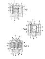
- FIGS 1 and 2 show schematically embodiments of known types of transducers.
- the pressure in the combustion chamber acts on a measuring surface 1.
- a membrane 2 seals the transducer housing 3 against the combustion chamber.
- the compressive force (product of the pressure p and the measuring surface) is passed to the measuring element 6 via a force introduction piece 4 and an intermediate part 5, which serves to compensate for thermal expansions and the electrical insulation, and via an electrode 7, a further electrically insulating intermediate part 8 and transfer an abutment 9 to the housing 3.
- a pretensioning spring 10 has the task of holding the described core pieces 4 to 9 together at high unsteady forces, reducing gap suspension and thus achieving a high natural frequency.
- the structure of the measuring element 6 is different for the two types of transducers.
- a plurality of single-crystal wafers made of x-cut quartz are usually packed in a measuring stack and electrically connected in such a way that the force acts equally on all wafers and the electrical charges on the surfaces are measured perpendicular to the direction of force, ie in the longitudinal direction and be added.
- the electrode 7 and electrical measuring lines lead the La to a miniature connector 40.
- the crystals are mechanically in series and electrically parallel.
- the transmission factor multiplies according to the number of crystals.
- the electrical insulation 5 and 7 can be saved by suitable design of the quartz disks.
- the transmission factor of the measuring element depends on the geometric dimensions of the crystal disk.
- the charge yield can be increased within limits by a suitable choice of dimensions, for example, corresponding to ten quartz disks in the longitudinal effect.
- the crystal cut (xyt) 155 ° is generally used for the transverse effect in quartz.
- the transmission factor for this cut is temperature-compensated for the longitudinal effect, i.e.
- this crystal cut has a greater resistance under compressive stress than the x-cut against the so-called "twin formation", a conversion of the crystalline structure which is detrimental to the measuring effect.
- the transverse effect is more suitable for uncooled pressure transducers at high temperatures up to 600 K than the longitudinal effect.
- FIG. 3 A schematic representation of a shear-type pressure sensor according to the invention is shown in FIG. 3 on a sensor with two mechanically connected measuring elements.
- the pressure p acts on the measuring surface 11.
- Membrane 12 dich tet transducer housing 13 against the combustion chamber.
- the compressive force is transmitted via force introduction piece 14 - called the stamp - to the measuring elements which are arranged on the side of the stamp 14.
- a measuring element consists of intermediate parts 15 for electrical insulation, electrodes 16 for removing the electrical charges, piezoelectric elements 17 and force introduction pieces 18. Abutments 19 conduct the force transmitted by the measuring elements to the housing 13.
- the measuring elements are subjected to thrust by the measuring force.
- a preferably annular biasing spring 20 holds the measuring elements together.
- the abutments 19 could also serve as a biasing spring with a suitable shape and assembly in a space-saving manner. However, it is advisable to divide the functions into different components 19 and 20, since the biasing spring is not stressed by the measuring force and is therefore independent of the measuring force.
- An elastically deformed inner part can also serve for pretensioning; for this purpose, the inner force introduction piece 14 (stamp) is preferably designed to be divided in the axial direction, the two parts exerting an outward force on the measuring elements by means of a resilient element.
- the stamp 14 itself can be used as a spring if it is slit to a certain extent.
- the pretension should preferably be applied during assembly by deformation or by an expansion element.
- the insulating parts 15 can also be replaced by crystals, so that doubled with a suitable orientation of the crystal cuts and electrical parallel connection of the Ubertra g ungs- factor. It is also possible to interchange the insulating parts 15 with the crystals 17 and, if the construction is suitable, to eliminate the force introduction pieces 18.
- the solution to the above object also depends on a suitable piezoelectric material and on the crystal cut.
- a suitable piezoelectric material In addition to the previously used quartz, which has the disadvantages mentioned, only a few other crystals are suitable for high temperature conditions. Because of its high Cu rie temperature, good mechanical and piezoelectric properties and low temperature dependence and stability of its properties, lithium niobate is preferred as the model material.
- Other suitable crystals for example tourmaline and lithium tantalate, can also advantageously be used.
- these are on their main sides preferably provided with electrodes which are to be carried out using thin-film technology, in particular by sputtering or vapor deposition, or using thick-film technology.
- the internal combustion chamber pressure to be measured acts on measuring surface 21.
- Membrane 22 seals transducer housing 23 against the combustion chamber and transmits the measuring force via its inner part to a force introduction piece 24, called a stamp.
- the force is applied over two parts. Both parts each contain an annular protrusion which, in conjunction with an intermediate protrusion on abutments 29, provides an overload protection or a protection against parts falling out.
- the positive connection surfaces of both parts are pre-tensioned by means of a thread.
- the pressure force in the punch 24 exerts thrust forces on measuring elements on both sides of the punch 24, which are received by abutment 29 and transmitted to the housing 23.
- the measuring elements consist of insulating elements 25, electrodes 26, piezoelectric elements 27 and external force introduction parts 28.
- the insulating elements 25 consist of quartz glass panes of the same dimensions as the piezoelectric elements 27 and can be replaced by such.
- the electrodes 26 are made of special expansion alloys. Test leads, only hinted at here, are hard-soldered to the electrodes 26 and lead to pin 42 of a miniature plug.
- the preferred crystal cut of lithium niobate is used for the piezoelectric elements 27, as described above.
- the measuring elements are biased by means of a biasing spring 30.
- the biasing spring is preferably designed as an annular spiral spring tensioned in the assembly process in order to achieve long spring travel.
- the prestressing force is preferably introduced in a punctiform manner onto the abutment 29 by this spring in order to apply edge pressure and other constraining forces on the piezoelectric element trical elements 27 and insulating elements 25 to reduce, as shown in Figures 4 and 7.
- a precisely adapted shape of the abutment 29 can advantageously also be used in order to ensure a uniform force distribution, as shown in FIGS. 5 and 6. Edge pressure is avoided in that the force introduction pieces 28 are designed with severely broken edges, as in FIGS. 5 and 6, or with a substantially cylindrical surface, as in FIGS. 4 and 7.
- the prestressing force and the measuring force in the transmitted essentially linearly between the abutments 29 and the force introduction elements 28.
- a point-like force transmission is also conceivable, such as between prestressing spring 30 and abutments 29. Since the measuring force should exert a shear stress in the measuring element, this embodiment is less recommendable.
- the force introduction elements 28 are made of ceramic material, the insulating parts 25 and electrodes 26 can be omitted to save space.
- thick-film electrodes are preferably attached to parts of the ceramic surfaces and measurement lines are soldered on to discharge the measurement charges.
- tensions 31 can advantageously be introduced, which can be pressed outwards by tension nuts 32 via a cone at their connection point and in turn further tension the adjacent pretensioning spring 30.
- an adjustable overload bolt 34 which limits the path of the punch 24, can advantageously be inserted into the clamping nut 32.
- Lock nut 35 secures the screw connection and is suitable for clamping the measuring lines in a groove of the clamping nut 32, which is indicated in FIGS. 4 and 6.
- the abutment 29, the housing 23 and the membrane 22 are welded on the pressure-facing side of the receptacle mers connected. Thread and sealing surface on the housing 23 are used for installation in an indexing bore on internal combustion engines.
- a lower housing part 33 is welded to the transducer housing 23. This lower part contains a miniature plug insulated and sealed with Teflon, consisting of Teflon part 41, plug pin 42, sleeve 43, seal 44 and locking nut 45.
Landscapes
- Chemical & Material Sciences (AREA)
- Engineering & Computer Science (AREA)
- Combustion & Propulsion (AREA)
- Physics & Mathematics (AREA)
- General Physics & Mathematics (AREA)
- Measuring Fluid Pressure (AREA)
Applications Claiming Priority (2)
| Application Number | Priority Date | Filing Date | Title |
|---|---|---|---|
| DE3545682 | 1985-12-21 | ||
| DE19853545682 DE3545682A1 (de) | 1985-12-21 | 1985-12-21 | Druckaufnehmer fuer den brennrauminnendruck in brennkraftmaschinen |
Publications (3)
| Publication Number | Publication Date |
|---|---|
| EP0226742A2 true EP0226742A2 (fr) | 1987-07-01 |
| EP0226742A3 EP0226742A3 (en) | 1988-06-22 |
| EP0226742B1 EP0226742B1 (fr) | 1990-12-05 |
Family
ID=6289319
Family Applications (1)
| Application Number | Title | Priority Date | Filing Date |
|---|---|---|---|
| EP86114305A Expired - Lifetime EP0226742B1 (fr) | 1985-12-21 | 1986-10-16 | Capteur de pression pour mesurer des pressions à hautes températures |
Country Status (3)
| Country | Link |
|---|---|
| US (1) | US4712036A (fr) |
| EP (1) | EP0226742B1 (fr) |
| DE (2) | DE3545682A1 (fr) |
Cited By (1)
| Publication number | Priority date | Publication date | Assignee | Title |
|---|---|---|---|---|
| WO2013167422A1 (fr) * | 2012-05-11 | 2013-11-14 | Robert Bosch Gmbh | Ensemble membrane pour un dispositif de mesure de pression |
Families Citing this family (13)
| Publication number | Priority date | Publication date | Assignee | Title |
|---|---|---|---|---|
| NO174309C (no) * | 1987-04-24 | 1994-04-13 | Norske Stats Oljeselskap | Elektroakustisk transducer for anordning i et gassformig fluid, særlig for måling av strömningsghastigheten i et rör under eksplosjonsfarlige forhol |
| TW221491B (fr) * | 1990-03-16 | 1994-03-01 | Matsushita Electric Industrial Co Ltd | |
| US5739626A (en) * | 1991-04-27 | 1998-04-14 | Ngk Spark Plug Co., Ltd. | Piezoelectric sensor |
| US5230921A (en) * | 1992-08-04 | 1993-07-27 | Blacktoe Medical, Inc. | Flexible piezo-electric membrane |
| DE4329055A1 (de) * | 1993-08-28 | 1995-03-02 | Teves Gmbh Alfred | Druckdichter Wandler für Kraftfahrzeuge |
| US6057628A (en) * | 1997-12-01 | 2000-05-02 | Board Of Regents Of The University Of Nebraska | Piezoelectric sensors/actuators for use in refractory environments |
| GB2351601B (en) * | 1999-06-29 | 2004-02-11 | Asahi Glass Co Ltd | Glass funnel for a cathode ray tube and a cathode ray tube |
| EP1486653B1 (fr) * | 2003-06-12 | 2016-04-13 | Denso Corporation | Capteur de pression de combustion |
| US8297133B2 (en) * | 2005-06-20 | 2012-10-30 | S.W.A.C. Schmitt-Walter Automation Consult Gmbh | Pressure sensor |
| EP2325997B1 (fr) * | 2008-09-09 | 2014-03-19 | Murata Manufacturing Co. Ltd. | Dispositif de génération de puissance piézoélectrique |
| CH711008A1 (de) * | 2015-04-30 | 2016-10-31 | Kistler Holding Ag | Kontaktkraft-Prüfvorrichtung, Verwendung einer solchen Kontaktkraft-Prüfvorrichtung und Verfahren zur Herstellung einer solchen Kontaktkraft-Prüfvorrichtung. |
| JP6541601B2 (ja) * | 2016-03-29 | 2019-07-10 | シチズンファインデバイス株式会社 | 圧力検出装置および圧電素子 |
| CN111158528B (zh) * | 2019-12-31 | 2021-06-29 | 北京航空航天大学 | 提高压电触摸屏在阶梯力下测力准确度的装置及方法 |
Family Cites Families (12)
| Publication number | Priority date | Publication date | Assignee | Title |
|---|---|---|---|---|
| AT280654B (de) * | 1968-02-23 | 1970-04-27 | Vibro Meter Ag | Meßwandler für die Druck-, Kraft- oder Beschleunigungsmessung |
| US3735161A (en) * | 1971-12-23 | 1973-05-22 | Bell & Howell Co | Piezoelectric transducer |
| CH537013A (de) * | 1972-05-08 | 1973-05-15 | Kistler Instrumente Ag | Druckmesswandler |
| US4072871A (en) * | 1974-05-20 | 1978-02-07 | Westinghouse Electric Corp. | Electroacoustic transducer |
| US4211951A (en) * | 1976-03-29 | 1980-07-08 | Bruel & Kjaer A/S | Shear type prestressed piezoelectric force transducer |
| US4052628A (en) * | 1976-04-19 | 1977-10-04 | Gulton Industries, Inc. | Dynamic, shear-mode piezoelectric pressure sensor |
| US4180892A (en) * | 1978-04-18 | 1980-01-01 | Bruel & Kjaer Industri A/S | Method for the manufacture of a force transducer |
| DE2906407C2 (de) * | 1979-02-20 | 1981-02-26 | Kistler Instrumente Ag, Winterthur (Schweiz) | Piezoelektrisches Wandlerelement zum Einbau in Druck-, Kraft- oder Beschleunigungsaufnehmer |
| DE3021452A1 (de) * | 1980-06-06 | 1981-12-24 | Siemens AG, 1000 Berlin und 8000 München | Verbesserung an einem drucksensor fuer verbrennungsmotor |
| ATE17523T1 (de) * | 1982-04-06 | 1986-02-15 | Kistler Instrumente Ag | Hochdruckaufnehmer. |
| AT384676B (de) * | 1983-07-07 | 1987-12-28 | Avl Verbrennungskraft Messtech | Messwertaufnehmer zur messung heisser medien und verfahren zur montage eines als druckaufnehmerausgebildeten messwertaufnehmers |
| GB2154323B (en) * | 1984-02-14 | 1987-02-18 | Plessey Co Plc | Pressure sensor |
-
1985
- 1985-12-21 DE DE19853545682 patent/DE3545682A1/de not_active Withdrawn
-
1986
- 1986-10-16 DE DE8686114305T patent/DE3676060D1/de not_active Expired - Lifetime
- 1986-10-16 EP EP86114305A patent/EP0226742B1/fr not_active Expired - Lifetime
- 1986-12-16 US US06/942,402 patent/US4712036A/en not_active Expired - Fee Related
Cited By (1)
| Publication number | Priority date | Publication date | Assignee | Title |
|---|---|---|---|---|
| WO2013167422A1 (fr) * | 2012-05-11 | 2013-11-14 | Robert Bosch Gmbh | Ensemble membrane pour un dispositif de mesure de pression |
Also Published As
| Publication number | Publication date |
|---|---|
| EP0226742A3 (en) | 1988-06-22 |
| DE3545682A1 (de) | 1987-06-25 |
| EP0226742B1 (fr) | 1990-12-05 |
| DE3676060D1 (de) | 1991-01-17 |
| US4712036A (en) | 1987-12-08 |
Similar Documents
| Publication | Publication Date | Title |
|---|---|---|
| EP0226742A2 (fr) | Capteur de pression pour mesurer des pressions à hautes températures | |
| EP0040390B1 (fr) | Détecteur de pression pour un moteur à combustion interne | |
| DE3026617C2 (de) | Meßanordnung | |
| DE3887642T2 (de) | Zylinderdruckwandler für einen Verbrennungsmotor. | |
| EP0407397B1 (fr) | Capteur de mesure de la pression a l'interieur de la chambre de combustion de moteurs a combustion interne | |
| EP0718612B1 (fr) | Bougie avec élément de mesure de force et isolateur divisé | |
| EP0594796B1 (fr) | Detecteur de cognement | |
| EP0016858B1 (fr) | Elément transducteur piézoélectrique destiné à être monté dans des capteurs de pression, de puissance ou d'accélération | |
| DE2709834A1 (de) | Kapazitiver druckfuehler | |
| DE1929478A1 (de) | Piezomesszelle | |
| EP2013597B1 (fr) | Élément de mesure piézoélectrique à effet transversal, et capteur équipé de cet élément de mesure | |
| DE1228448B (de) | Beschleunigungsmessgeraet mit Temperaturkompensation | |
| EP2174107B1 (fr) | Capteur de pression piézoélectrique | |
| EP3289327B1 (fr) | Dispositif de vérification de force de contact, utilisation d'un tel dispositif de vérification de force de contact et procédé de réalisation d'un tel dispositif de vérification de force de contact | |
| DE3423711C2 (de) | Meßwertaufnehmer zur Messung heißer Medien, sowie Verfahren zu seiner Montage | |
| CH664235A5 (de) | Piezoelektrisches messelement. | |
| DE69311918T2 (de) | Quarzkristalldruckwandler | |
| DE3702412C2 (fr) | ||
| EP0995979B1 (fr) | Capteur de pression | |
| DE4010609A1 (de) | Zuendkerze mit temperatur- und druckerfassung | |
| AT503664A4 (de) | Piezoelektrischer drucksensor | |
| EP3289326A1 (fr) | Dispositif de vérification de force de contact, utilisation d'un tel dispositif de vérification de force de contact et procédé de réalisation d'un tel dispositif de vérification de force de contact | |
| DE1955040A1 (de) | Piezoelektrischer Beschleunigungsmesswandler | |
| DE102004047143A1 (de) | Piezoelektrischer Brennraum-Drucksensor mit einem Druckübertragungsstift | |
| DE1573628B2 (de) | Beschleunigungs- und temperaturkompensierter piezoelektrischer druck- oder kraftmesswandler |
Legal Events
| Date | Code | Title | Description |
|---|---|---|---|
| PUAI | Public reference made under article 153(3) epc to a published international application that has entered the european phase |
Free format text: ORIGINAL CODE: 0009012 |
|
| AK | Designated contracting states |
Kind code of ref document: A2 Designated state(s): DE FR GB IT SE |
|
| PUAL | Search report despatched |
Free format text: ORIGINAL CODE: 0009013 |
|
| RHK1 | Main classification (correction) |
Ipc: G01L 9/08 |
|
| AK | Designated contracting states |
Kind code of ref document: A3 Designated state(s): DE FR GB IT SE |
|
| 17P | Request for examination filed |
Effective date: 19881212 |
|
| 17Q | First examination report despatched |
Effective date: 19900327 |
|
| ITF | It: translation for a ep patent filed | ||
| GRAA | (expected) grant |
Free format text: ORIGINAL CODE: 0009210 |
|
| AK | Designated contracting states |
Kind code of ref document: B1 Designated state(s): DE FR GB IT SE |
|
| ET | Fr: translation filed | ||
| REF | Corresponds to: |
Ref document number: 3676060 Country of ref document: DE Date of ref document: 19910117 |
|
| GBT | Gb: translation of ep patent filed (gb section 77(6)(a)/1977) | ||
| PLBE | No opposition filed within time limit |
Free format text: ORIGINAL CODE: 0009261 |
|
| STAA | Information on the status of an ep patent application or granted ep patent |
Free format text: STATUS: NO OPPOSITION FILED WITHIN TIME LIMIT |
|
| ITTA | It: last paid annual fee | ||
| 26N | No opposition filed | ||
| PGFP | Annual fee paid to national office [announced via postgrant information from national office to epo] |
Ref country code: SE Payment date: 19920911 Year of fee payment: 7 |
|
| PGFP | Annual fee paid to national office [announced via postgrant information from national office to epo] |
Ref country code: DE Payment date: 19920923 Year of fee payment: 7 |
|
| PGFP | Annual fee paid to national office [announced via postgrant information from national office to epo] |
Ref country code: FR Payment date: 19920929 Year of fee payment: 7 |
|
| PGFP | Annual fee paid to national office [announced via postgrant information from national office to epo] |
Ref country code: GB Payment date: 19921014 Year of fee payment: 7 |
|
| PG25 | Lapsed in a contracting state [announced via postgrant information from national office to epo] |
Ref country code: GB Effective date: 19931016 |
|
| PG25 | Lapsed in a contracting state [announced via postgrant information from national office to epo] |
Ref country code: SE Effective date: 19931017 |
|
| GBPC | Gb: european patent ceased through non-payment of renewal fee |
Effective date: 19931016 |
|
| PG25 | Lapsed in a contracting state [announced via postgrant information from national office to epo] |
Ref country code: FR Effective date: 19940630 |
|
| PG25 | Lapsed in a contracting state [announced via postgrant information from national office to epo] |
Ref country code: DE Effective date: 19940701 |
|
| REG | Reference to a national code |
Ref country code: FR Ref legal event code: ST |
|
| EUG | Se: european patent has lapsed |
Ref document number: 86114305.5 Effective date: 19940510 |
|
| PG25 | Lapsed in a contracting state [announced via postgrant information from national office to epo] |
Ref country code: IT Free format text: LAPSE BECAUSE OF NON-PAYMENT OF DUE FEES Effective date: 20051016 |