EP0226783A2 - Fermeture de garantie - Google Patents
Fermeture de garantie Download PDFInfo
- Publication number
- EP0226783A2 EP0226783A2 EP86115494A EP86115494A EP0226783A2 EP 0226783 A2 EP0226783 A2 EP 0226783A2 EP 86115494 A EP86115494 A EP 86115494A EP 86115494 A EP86115494 A EP 86115494A EP 0226783 A2 EP0226783 A2 EP 0226783A2
- Authority
- EP
- European Patent Office
- Prior art keywords
- closure
- ring
- container
- flange
- insert ring
- Prior art date
- Legal status (The legal status is an assumption and is not a legal conclusion. Google has not performed a legal analysis and makes no representation as to the accuracy of the status listed.)
- Withdrawn
Links
Images

Classifications
-
- B—PERFORMING OPERATIONS; TRANSPORTING
- B65—CONVEYING; PACKING; STORING; HANDLING THIN OR FILAMENTARY MATERIAL
- B65D—CONTAINERS FOR STORAGE OR TRANSPORT OF ARTICLES OR MATERIALS, e.g. BAGS, BARRELS, BOTTLES, BOXES, CANS, CARTONS, CRATES, DRUMS, JARS, TANKS, HOPPERS, FORWARDING CONTAINERS; ACCESSORIES, CLOSURES, OR FITTINGS THEREFOR; PACKAGING ELEMENTS; PACKAGES
- B65D47/00—Closures with filling and discharging, or with discharging, devices
- B65D47/04—Closures with discharging devices other than pumps
- B65D47/06—Closures with discharging devices other than pumps with pouring spouts or tubes; with discharge nozzles or passages
- B65D47/061—Closures with discharging devices other than pumps with pouring spouts or tubes; with discharge nozzles or passages with telescopic, retractable or reversible spouts, tubes or nozzles
- B65D47/063—Closures with discharging devices other than pumps with pouring spouts or tubes; with discharge nozzles or passages with telescopic, retractable or reversible spouts, tubes or nozzles with flexible parts
-
- B—PERFORMING OPERATIONS; TRANSPORTING
- B65—CONVEYING; PACKING; STORING; HANDLING THIN OR FILAMENTARY MATERIAL
- B65D—CONTAINERS FOR STORAGE OR TRANSPORT OF ARTICLES OR MATERIALS, e.g. BAGS, BARRELS, BOTTLES, BOXES, CANS, CARTONS, CRATES, DRUMS, JARS, TANKS, HOPPERS, FORWARDING CONTAINERS; ACCESSORIES, CLOSURES, OR FITTINGS THEREFOR; PACKAGING ELEMENTS; PACKAGES
- B65D47/00—Closures with filling and discharging, or with discharging, devices
- B65D47/04—Closures with discharging devices other than pumps
- B65D47/06—Closures with discharging devices other than pumps with pouring spouts or tubes; with discharge nozzles or passages
- B65D47/12—Closures with discharging devices other than pumps with pouring spouts or tubes; with discharge nozzles or passages having removable closures
- B65D47/122—Threaded caps
Definitions
- the invention relates to a guarantee closure for liquid containers with an insert ring with flange to be inserted into a generally circular opening of the container, a pouring spout, a closure lid closing the pouring spout, a bellows connecting the insert ring and the pouring spout and a hinged ring bracket attached to the closure lid in at least one point .
- Such closures have long been known both for metal and for plastic or cardboard containers.
- the insert ring of the closure serves to fix the closure in the container opening in a liquid-tight manner.
- Etalldeckeln in closures for metal containers and for containers with M includes this insert ring has a circumferential annular groove, into which the flanged edge of the container mounted in the cover and engages a generally circular opening.
- This groove is formed by an annular bead-like projection, which is formed below the groove on the outside of the insert ring, and by a flange, which generally forms the upper edge of the insert ring and which rests on the surface of the container lid immediately surrounding the opening.
- the insert ring is made of a relatively soft plastic (e.g. high-pressure polyethylene), it is possible to insert it into the container opening with a certain amount of force, whereby the annular bead-like projection, which has a larger outer diameter than the container opening, is briefly compressed and collapses then expands back to its previous extent.
- a relatively soft plastic e.g. high-pressure polyethylene
- the diameter of the ring groove, the projection, the container opening and the flange are chosen so that the inserted plastic ring rests liquid-tight on the edge of the container opening, the flange preventing the closure from being pressed fully into the interior of the container, while the projection pulls out the entire closure prevent container opening.
- the insert ring is generally connected via a bellows to a pouring spout, which in turn is closed by a cover.
- the bellows can be turned in and out, and the pouring spout and bellows are dimensioned such that the closure lid sitting on the pouring spout is essentially flush with the surface of the container or protrudes only slightly over the surface of the container, while the pouring spout is in the turned-out state is located at a clear distance above the container surface, which makes it easier to pour out the liquid in the container.
- one R is attached to the closure cap, which is screwed, in general, with the pouring spout attached ingbügel so that is pulled out in a strong train on the ring-pull of the cap with the spout by the eversion of the bellows out of the insert ring.
- the projection of the insert ring must absorb the forces that occur without sliding through the container opening.
- the invention is therefore based on the object of providing a closure for liquid containers with the features mentioned at the outset, which can practically not be removed from the container opening without externally clearly visible changes.
- covers at unopened closure of the annular strap, together with the closure lid flange broadly and encompasses that the R closely abuts the opening surrounding container surface ingbügel that by manually tearable tabs he at least in its flip-up region with the Closure cover is connected and / or that the closure cover and / or the ring bracket by appropriate tabs with the insert ring or Container surface are connected.
- the insert ring must be ovalized and pried out or pulled out of the opening in order to remove the closure from the container.
- the insert ring cannot be reached without first lifting the ring bracket and / or the closure cover and thus at least partially bulging out the bellows.
- this provides a noticeable resistance to the lifting of the cover, whereby the tabs, which connect either the ring bracket and the cover ring or the ring bracket and the insert ring or the closure cover and the insert ring, tear and so make any attempt at manipulation obvious.
- connection options of the tabs are not mutually exclusive and can be present at the same closure at the same time. In general, however, one type of connection is sufficient to ensure the purpose of the invention.
- the tabs have predetermined breaking points.
- Such predetermined breaking points can be arranged so that the torn tabs are clearly visible from the outside.
- the tabs are under a pretension, by means of which, after they have been torn off, their free end visibly protrudes from their previous attachment point.
- Such a design of the tabs facilitates the detection of tampering with the container closure.
- Ringbü g el and / or the closure cover with tabs diametrically opposite welding strips are connected, which in turn have a large-area welded connection to the flange of the insert ring.
- the ring bracket covers a bead concentrically surrounding the container opening and the flange of the insert ring in the container surface.
- closure cap is a screw having a toothing in the outer region of its underside which engages with un g eworkem closure in a counter toothing which is mounted on the surface of the flange, in the form of an anti-rotation .
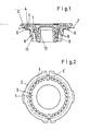
- the closure shown in FIGS. 1 and 2 has practically along the entire circumference of the closure cover 1 tabs 3 which are connected to the ring bracket 2 at predetermined breaking points 4.
- the R ingbügel 2 encloses both the cap 1 and the flange 5 of the insert ring 6.
- closure cap 1 and ring bracket 2 together cover the flange 5 of the insert ring 6 completely.
- the container surface 7 also has a step-shaped shoulder 8 which surrounds the container opening in a ring, so that the flange 5 lies in a corresponding recess.
- the ring bracket 2 lies outside the shoulder 8 on the container surface 7.
- the insert ring 6 by gripping under the flange 5 to be levered out of the container opening, the ingbügel R 2 must be raised a considerable piece for this purpose necessarily.
- the tabs 3 tear off at the predetermined breaking points 4 from the ring bracket 2 and thus make the attempt at manipulation obvious.
- the closure cap 1 as in all the other embodiments shown here, is designed as a screw cap, which is screwed onto the pouring spout 10 firmly and in a liquid-tight manner via the thread 9.
- the pouring spout 10 is connected to the insert ring 6 via the bellows 11.
- Fig. 2 also tabs 3 'can be seen, which have no predetermined breaking points 4 and thus produce a flexible, but nevertheless firm connection between the semicircular parts of the ring bracket 2 and the closure cover 1.
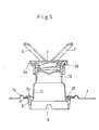
- FIGS. 3 to 5 differs from the aforementioned embodiment in several respects.
- the surface of the container has an annular bead 14 running around the container opening.
- this ring bead 14 is completely covered by the ring bracket 2.
- the flange 5 cannot be levered up by tools or the like without the ring bracket 2 being raised and the tabs 3 thus being torn off.
- 3 to 5 are additional to the tabs 3 and 3 'to recognize further tabs 3a, which establish a connection between the closure cover 1 and the flange 5 of the insert ring 6.
- the embodiment shown here also has an inner membrane seal 12 which closes the pouring spout 10 in its interior and can be pulled out by a ring 13. Furthermore, the already mentioned toothing 15, which acts as an anti-rotation device, is indicated in FIG. 4 by dashed lines.
- Fig. 5 shows the closure just described in everted condition, whereby the individual parts, in particular the closure cap 1, the R ingbügel 2 and the torn off flap 3a can be seen very clearly.
- the fastening g ung the tab 3a on the flange 5 is effected by ultrasonic welding.
- the insert ring 6 shown in FIG. 5 has a notch or a groove 16 in its lower region, through which the residual emptying of the container is improved.
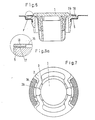
- FIGs. 6, 6a and 7 another embodiment is shown, in which the R 2 ingbügel- 3b via tabs welding strips 18 attached, which are joined by ultrasonic welding firmly to the flange 5 of the insert ring 6.
- This ensures that the ring bracket 2 and / or the closure cover 1 can only be lifted off the flange 5 by tearing the tabs 3b, so that any manipulation of the Contents of the container, which would be accomplished by prying out or pulling the entire closure out of the container opening, are immediately visible.
- Strength in F. 6a is a detail from FIG. 6, but is shown before the welded connection is made. In this ar- D position to recognize the energy directors 17, which can be seen as a wedge-shaped elevation of the flange. 5 Such e nergieggisgeber is very convenient for the placement of the ultrasonic energy in the desired range.
- FIGS. 1 to 5 have locking cams 19 on the outer edge of the closure cover 1, which is designed as a screw cap in all other embodiments, which can be locked into locking grooves 20 of the insert ring 6, so that this also results in a certain stiffness when lifting the cover 1 and the parts of the ring bracket 2 connected to it is reached. This ensures that the tabs tear off prematurely when the ring bracket 2 is lifted.
Landscapes
- Engineering & Computer Science (AREA)
- Mechanical Engineering (AREA)
- Closures For Containers (AREA)
Applications Claiming Priority (2)
| Application Number | Priority Date | Filing Date | Title |
|---|---|---|---|
| DE19853545548 DE3545548A1 (de) | 1985-12-21 | 1985-12-21 | Garantieverschluss |
| DE3545548 | 1985-12-21 |
Publications (2)
| Publication Number | Publication Date |
|---|---|
| EP0226783A2 true EP0226783A2 (fr) | 1987-07-01 |
| EP0226783A3 EP0226783A3 (fr) | 1988-10-12 |
Family
ID=6289236
Family Applications (1)
| Application Number | Title | Priority Date | Filing Date |
|---|---|---|---|
| EP86115494A Withdrawn EP0226783A3 (fr) | 1985-12-21 | 1986-11-08 | Fermeture de garantie |
Country Status (2)
| Country | Link |
|---|---|
| EP (1) | EP0226783A3 (fr) |
| DE (1) | DE3545548A1 (fr) |
Cited By (7)
| Publication number | Priority date | Publication date | Assignee | Title |
|---|---|---|---|---|
| EP0385104A1 (fr) * | 1989-02-28 | 1990-09-05 | Jacob Berg GmbH & Co. KG | Fermeture en plastique à bande arrachable |
| US5088632A (en) * | 1989-01-23 | 1992-02-18 | Astra Plastique | Liquid-tight closure assembly with multidirectional orientation and retractible pourer tube |
| WO1997047530A1 (fr) * | 1996-06-08 | 1997-12-18 | Herberts Gesellschaft mit beschränkter Haftung | Dispositif pour la fermeture de recipients |
| US5899364A (en) * | 1997-08-05 | 1999-05-04 | Rieke Corporation | Insert molded tamper evident pouring spout |
| US5950876A (en) * | 1997-08-05 | 1999-09-14 | Rieke Corporation | Insert molded tamper evident pouring spout |
| US6106261A (en) * | 1998-08-31 | 2000-08-22 | John W. Von Holdt | Apparatus for molding a one-piece article in a single molding operation using two different plastic materials |
| EP1997743A1 (fr) * | 2007-05-31 | 2008-12-03 | Rieke Corporation | Fermeture de récipient et bouchon de fermeture doté d'anses profilées |
Families Citing this family (2)
| Publication number | Priority date | Publication date | Assignee | Title |
|---|---|---|---|---|
| DE3730225A1 (de) * | 1987-09-09 | 1989-03-23 | Berg Jacob Gmbh Co Kg | Kunststoffverschluss fuer einen kunststoffbehaelter |
| DE29716230U1 (de) * | 1997-09-10 | 1997-11-27 | Leifeld und Lemke Fülltechnik GmbH & Co. KG, 48683 Ahaus | Verpackung für fließfähige Medien |
Family Cites Families (6)
| Publication number | Priority date | Publication date | Assignee | Title |
|---|---|---|---|---|
| US3199750A (en) * | 1963-02-13 | 1965-08-10 | Jay G Livingstone | Cover for extensible spout, releasable as spout is extended |
| FR1533032A (fr) * | 1966-08-04 | 1968-07-12 | Bouchon de fermeture pour l'orifice de prélèvement de récipients | |
| DE1968009U (de) * | 1967-06-03 | 1967-09-07 | Paul Schulze & Co G M B H Nord | Verschlusseinsatz aus kunststoff fuer fluessigkeitsbehaelter. |
| US4236629A (en) * | 1978-10-02 | 1980-12-02 | American Flange & Manufacturing Co. Inc. | Nestable pouring spout assembly |
| FR2487301A1 (fr) * | 1980-07-23 | 1982-01-29 | Bouchons Plastiques | Goulot escamotable par cloquage comprenant un systeme de garantie |
| US4618078A (en) * | 1984-05-16 | 1986-10-21 | Rieke Corporation | Vented nestable pouring spout |
-
1985
- 1985-12-21 DE DE19853545548 patent/DE3545548A1/de not_active Withdrawn
-
1986
- 1986-11-08 EP EP86115494A patent/EP0226783A3/fr not_active Withdrawn
Cited By (9)
| Publication number | Priority date | Publication date | Assignee | Title |
|---|---|---|---|---|
| US5088632A (en) * | 1989-01-23 | 1992-02-18 | Astra Plastique | Liquid-tight closure assembly with multidirectional orientation and retractible pourer tube |
| EP0385104A1 (fr) * | 1989-02-28 | 1990-09-05 | Jacob Berg GmbH & Co. KG | Fermeture en plastique à bande arrachable |
| WO1997047530A1 (fr) * | 1996-06-08 | 1997-12-18 | Herberts Gesellschaft mit beschränkter Haftung | Dispositif pour la fermeture de recipients |
| US5899364A (en) * | 1997-08-05 | 1999-05-04 | Rieke Corporation | Insert molded tamper evident pouring spout |
| US5950876A (en) * | 1997-08-05 | 1999-09-14 | Rieke Corporation | Insert molded tamper evident pouring spout |
| US5967376A (en) * | 1997-08-05 | 1999-10-19 | Rieke Corporation | Insert molded tamper evident pouring spout |
| US6106261A (en) * | 1998-08-31 | 2000-08-22 | John W. Von Holdt | Apparatus for molding a one-piece article in a single molding operation using two different plastic materials |
| EP1997743A1 (fr) * | 2007-05-31 | 2008-12-03 | Rieke Corporation | Fermeture de récipient et bouchon de fermeture doté d'anses profilées |
| US7988007B2 (en) | 2007-05-31 | 2011-08-02 | Rieke Corporation | Container closure and closing cap having contoured bail handles |
Also Published As
| Publication number | Publication date |
|---|---|
| EP0226783A3 (fr) | 1988-10-12 |
| DE3545548A1 (de) | 1987-07-02 |
Similar Documents
| Publication | Publication Date | Title |
|---|---|---|
| EP0214095A2 (fr) | Fermeture en matière plastique | |
| DE3422546C2 (de) | Behälter-Verschlußkappe | |
| DE3410765C2 (de) | Behälterverschluß | |
| DE9318243U1 (de) | Kunststoff-Schraubkappe mit Garantieband und Fangband | |
| DE2652046C2 (de) | Schraubverschluß für Behälter | |
| EP2566768B1 (fr) | Emballage avec fermeture filetée | |
| EP0675051B1 (fr) | Capuchon à vis avec un anneau soudé | |
| CH643201A5 (de) | Verschlusskappe und verfahren zu ihrer herstellung. | |
| DE102014018155A1 (de) | Originalitätsverschluss für eine Zugangsöffnung eines Behälters, insbesondere einer Flasche | |
| DE4132896C1 (fr) | ||
| DE102013008861A1 (de) | Einschweißteil mit Sperrschicht | |
| DE29511368U1 (de) | Getränkedosenverschluß | |
| EP0296103A2 (fr) | Fermeture en plastique avec tige centrale d'étanchéité | |
| DE2226556C3 (de) | Schraubverschluß eines Flüssigkeitsbehälters | |
| WO2020126925A1 (fr) | Fermeture avec stabilisation de la bande d'inviolabilité | |
| DE3545548A1 (de) | Garantieverschluss | |
| DE19807768A1 (de) | Kunststoffdeckel mit Kunststoffverschluß | |
| EP0833781A1 (fr) | Opercule en matiere plastique | |
| EP0144829A2 (fr) | Fermeture pour récipient à goulot | |
| EP0498954B1 (fr) | Capuchon de fermeture pour fermeture en matière plastique | |
| DE4204427C1 (en) | Bottle closure with bottle neck closed by elastomer sealing element - involves holder cap with through hole in its face wall and tear-off element on upper side of face wall | |
| DE102014011539B4 (de) | Originalitätsverschluss für eine Zugangsöffnung eines Behälters, insbesondere einer Flasche | |
| DE19653065A1 (de) | Verpackung | |
| AT253375B (de) | Garantie-Verschlußstopfen für Flaschen od. dgl. | |
| DE2128886C3 (de) | Aufreißkappe aus Metall |
Legal Events
| Date | Code | Title | Description |
|---|---|---|---|
| PUAI | Public reference made under article 153(3) epc to a published international application that has entered the european phase |
Free format text: ORIGINAL CODE: 0009012 |
|
| AK | Designated contracting states |
Kind code of ref document: A2 Designated state(s): DE ES FR GB IT NL SE |
|
| PUAL | Search report despatched |
Free format text: ORIGINAL CODE: 0009013 |
|
| AK | Designated contracting states |
Kind code of ref document: A3 Designated state(s): DE ES FR GB IT NL SE |
|
| 17P | Request for examination filed |
Effective date: 19890227 |
|
| 17Q | First examination report despatched |
Effective date: 19890622 |
|
| STAA | Information on the status of an ep patent application or granted ep patent |
Free format text: STATUS: THE APPLICATION IS DEEMED TO BE WITHDRAWN |
|
| 18D | Application deemed to be withdrawn |
Effective date: 19910112 |
|
| RIN1 | Information on inventor provided before grant (corrected) |
Inventor name: DER ERFINDER HAT AUF SEINE NENNUNG VERZICHTET. |