EP0226788A1 - Elément à paroi perméable - Google Patents
Elément à paroi perméable Download PDFInfo
- Publication number
- EP0226788A1 EP0226788A1 EP86115521A EP86115521A EP0226788A1 EP 0226788 A1 EP0226788 A1 EP 0226788A1 EP 86115521 A EP86115521 A EP 86115521A EP 86115521 A EP86115521 A EP 86115521A EP 0226788 A1 EP0226788 A1 EP 0226788A1
- Authority
- EP
- European Patent Office
- Prior art keywords
- wall
- vessel
- element according
- interior
- permeable
- Prior art date
- Legal status (The legal status is an assumption and is not a legal conclusion. Google has not performed a legal analysis and makes no representation as to the accuracy of the status listed.)
- Granted
Links
Images

Classifications
-
- B—PERFORMING OPERATIONS; TRANSPORTING
- B01—PHYSICAL OR CHEMICAL PROCESSES OR APPARATUS IN GENERAL
- B01D—SEPARATION
- B01D65/00—Accessories or auxiliary operations, in general, for separation processes or apparatus using semi-permeable membranes
- B01D65/08—Prevention of membrane fouling or of concentration polarisation
-
- B—PERFORMING OPERATIONS; TRANSPORTING
- B01—PHYSICAL OR CHEMICAL PROCESSES OR APPARATUS IN GENERAL
- B01D—SEPARATION
- B01D29/00—Filters with filtering elements stationary during filtration, e.g. pressure or suction filters, not covered by groups B01D24/00 - B01D27/00; Filtering elements therefor
- B01D29/39—Filters with filtering elements stationary during filtration, e.g. pressure or suction filters, not covered by groups B01D24/00 - B01D27/00; Filtering elements therefor with hollow discs side by side on, or around, one or more tubes, e.g. of the leaf type
-
- B—PERFORMING OPERATIONS; TRANSPORTING
- B01—PHYSICAL OR CHEMICAL PROCESSES OR APPARATUS IN GENERAL
- B01D—SEPARATION
- B01D63/00—Apparatus in general for separation processes using semi-permeable membranes
- B01D63/08—Flat membrane modules
- B01D63/081—Manufacturing thereof
-
- B—PERFORMING OPERATIONS; TRANSPORTING
- B01—PHYSICAL OR CHEMICAL PROCESSES OR APPARATUS IN GENERAL
- B01D—SEPARATION
- B01D63/00—Apparatus in general for separation processes using semi-permeable membranes
- B01D63/08—Flat membrane modules
- B01D63/082—Flat membrane modules comprising a stack of flat membranes
-
- B—PERFORMING OPERATIONS; TRANSPORTING
- B01—PHYSICAL OR CHEMICAL PROCESSES OR APPARATUS IN GENERAL
- B01F—MIXING, e.g. DISSOLVING, EMULSIFYING OR DISPERSING
- B01F25/00—Flow mixers; Mixers for falling materials, e.g. solid particles
- B01F25/40—Static mixers
- B01F25/42—Static mixers in which the mixing is affected by moving the components jointly in changing directions, e.g. in tubes provided with baffles or obstructions
- B01F25/43—Mixing tubes, e.g. wherein the material is moved in a radial or partly reversed direction
- B01F25/431—Straight mixing tubes with baffles or obstructions that do not cause substantial pressure drop; Baffles therefor
- B01F25/4314—Straight mixing tubes with baffles or obstructions that do not cause substantial pressure drop; Baffles therefor with helical baffles
- B01F25/43141—Straight mixing tubes with baffles or obstructions that do not cause substantial pressure drop; Baffles therefor with helical baffles composed of consecutive sections of helical formed elements
-
- B—PERFORMING OPERATIONS; TRANSPORTING
- B01—PHYSICAL OR CHEMICAL PROCESSES OR APPARATUS IN GENERAL
- B01F—MIXING, e.g. DISSOLVING, EMULSIFYING OR DISPERSING
- B01F25/00—Flow mixers; Mixers for falling materials, e.g. solid particles
- B01F25/40—Static mixers
- B01F25/42—Static mixers in which the mixing is affected by moving the components jointly in changing directions, e.g. in tubes provided with baffles or obstructions
- B01F25/43—Mixing tubes, e.g. wherein the material is moved in a radial or partly reversed direction
- B01F25/431—Straight mixing tubes with baffles or obstructions that do not cause substantial pressure drop; Baffles therefor
- B01F25/4316—Straight mixing tubes with baffles or obstructions that do not cause substantial pressure drop; Baffles therefor the baffles being flat pieces of material, e.g. intermeshing, fixed to the wall or fixed on a central rod
- B01F25/43161—Straight mixing tubes with baffles or obstructions that do not cause substantial pressure drop; Baffles therefor the baffles being flat pieces of material, e.g. intermeshing, fixed to the wall or fixed on a central rod composed of consecutive sections of flat pieces of material
-
- B—PERFORMING OPERATIONS; TRANSPORTING
- B01—PHYSICAL OR CHEMICAL PROCESSES OR APPARATUS IN GENERAL
- B01J—CHEMICAL OR PHYSICAL PROCESSES, e.g. CATALYSIS OR COLLOID CHEMISTRY; THEIR RELEVANT APPARATUS
- B01J19/00—Chemical, physical or physico-chemical processes in general; Their relevant apparatus
- B01J19/32—Packing elements in the form of grids or built-up elements for forming a unit or module inside the apparatus for mass or heat transfer
-
- B—PERFORMING OPERATIONS; TRANSPORTING
- B01—PHYSICAL OR CHEMICAL PROCESSES OR APPARATUS IN GENERAL
- B01J—CHEMICAL OR PHYSICAL PROCESSES, e.g. CATALYSIS OR COLLOID CHEMISTRY; THEIR RELEVANT APPARATUS
- B01J4/00—Feed or outlet devices; Feed or outlet control devices
- B01J4/04—Feed or outlet devices; Feed or outlet control devices using osmotic pressure using membranes, porous plates
-
- B—PERFORMING OPERATIONS; TRANSPORTING
- B01—PHYSICAL OR CHEMICAL PROCESSES OR APPARATUS IN GENERAL
- B01D—SEPARATION
- B01D2321/00—Details relating to membrane cleaning, regeneration, sterilization or to the prevention of fouling
- B01D2321/20—By influencing the flow
- B01D2321/2008—By influencing the flow statically
- B01D2321/2016—Static mixers; Turbulence generators
-
- B—PERFORMING OPERATIONS; TRANSPORTING
- B01—PHYSICAL OR CHEMICAL PROCESSES OR APPARATUS IN GENERAL
- B01J—CHEMICAL OR PHYSICAL PROCESSES, e.g. CATALYSIS OR COLLOID CHEMISTRY; THEIR RELEVANT APPARATUS
- B01J2219/00—Chemical, physical or physico-chemical processes in general; Their relevant apparatus
- B01J2219/32—Details relating to packing elements in the form of grids or built-up elements for forming a unit of module inside the apparatus for mass or heat transfer
- B01J2219/322—Basic shape of the elements
- B01J2219/32203—Sheets
- B01J2219/3221—Corrugated sheets
-
- B—PERFORMING OPERATIONS; TRANSPORTING
- B01—PHYSICAL OR CHEMICAL PROCESSES OR APPARATUS IN GENERAL
- B01J—CHEMICAL OR PHYSICAL PROCESSES, e.g. CATALYSIS OR COLLOID CHEMISTRY; THEIR RELEVANT APPARATUS
- B01J2219/00—Chemical, physical or physico-chemical processes in general; Their relevant apparatus
- B01J2219/32—Details relating to packing elements in the form of grids or built-up elements for forming a unit of module inside the apparatus for mass or heat transfer
- B01J2219/322—Basic shape of the elements
- B01J2219/32203—Sheets
- B01J2219/32213—Plurality of essentially parallel sheets
-
- B—PERFORMING OPERATIONS; TRANSPORTING
- B01—PHYSICAL OR CHEMICAL PROCESSES OR APPARATUS IN GENERAL
- B01J—CHEMICAL OR PHYSICAL PROCESSES, e.g. CATALYSIS OR COLLOID CHEMISTRY; THEIR RELEVANT APPARATUS
- B01J2219/00—Chemical, physical or physico-chemical processes in general; Their relevant apparatus
- B01J2219/32—Details relating to packing elements in the form of grids or built-up elements for forming a unit of module inside the apparatus for mass or heat transfer
- B01J2219/322—Basic shape of the elements
- B01J2219/32203—Sheets
- B01J2219/32224—Sheets characterised by the orientation of the sheet
- B01J2219/32227—Vertical orientation
-
- B—PERFORMING OPERATIONS; TRANSPORTING
- B01—PHYSICAL OR CHEMICAL PROCESSES OR APPARATUS IN GENERAL
- B01J—CHEMICAL OR PHYSICAL PROCESSES, e.g. CATALYSIS OR COLLOID CHEMISTRY; THEIR RELEVANT APPARATUS
- B01J2219/00—Chemical, physical or physico-chemical processes in general; Their relevant apparatus
- B01J2219/32—Details relating to packing elements in the form of grids or built-up elements for forming a unit of module inside the apparatus for mass or heat transfer
- B01J2219/322—Basic shape of the elements
- B01J2219/32203—Sheets
- B01J2219/32237—Sheets comprising apertures or perforations
-
- B—PERFORMING OPERATIONS; TRANSPORTING
- B01—PHYSICAL OR CHEMICAL PROCESSES OR APPARATUS IN GENERAL
- B01J—CHEMICAL OR PHYSICAL PROCESSES, e.g. CATALYSIS OR COLLOID CHEMISTRY; THEIR RELEVANT APPARATUS
- B01J2219/00—Chemical, physical or physico-chemical processes in general; Their relevant apparatus
- B01J2219/32—Details relating to packing elements in the form of grids or built-up elements for forming a unit of module inside the apparatus for mass or heat transfer
- B01J2219/322—Basic shape of the elements
- B01J2219/32203—Sheets
- B01J2219/32255—Other details of the sheets
-
- B—PERFORMING OPERATIONS; TRANSPORTING
- B01—PHYSICAL OR CHEMICAL PROCESSES OR APPARATUS IN GENERAL
- B01J—CHEMICAL OR PHYSICAL PROCESSES, e.g. CATALYSIS OR COLLOID CHEMISTRY; THEIR RELEVANT APPARATUS
- B01J2219/00—Chemical, physical or physico-chemical processes in general; Their relevant apparatus
- B01J2219/32—Details relating to packing elements in the form of grids or built-up elements for forming a unit of module inside the apparatus for mass or heat transfer
- B01J2219/322—Basic shape of the elements
- B01J2219/32279—Tubes or cylinders
Definitions
- the invention relates to an element with a permeable wall, which is arranged in a vessel receiving a fluid flow, the wall being permeable to at least part of the fluid and delimiting an interior of the element which is connected to a space outside the vessel through the vessel wall.
- Such an element is e.g. known from GB-PS 2 011 796.
- a filtrate to be separated penetrates through the permeable wall into the interior of the element and is led away through this space and through the wall of the vessel into a space outside the vessel.
- the task is always to provide every single smallest part of the medium with the opportunity to deliver the portions corresponding to the filter opening as filtrate to separate collecting spaces for the filtrate.
- the filter is therefore the more effective the better it is possible to separate all filter-compatible parts from a given fluid flow.
- baffles are installed in the inflow of filtration surfaces, which cause braid flows in the wake downstream of the filtration surfaces. It is also known to actively move the filter surface itself transversely to the direction of passage of the mix. In many Applications are flow rates in the laminar range. The portion of the medium flow to be removed by the filtration should be allowed to come into contact with the filter surface for a sufficient time. The braid flows abate quickly and are not very effective for the downstream filter surfaces. Moving filter surfaces are already effective, but they require a great deal of technical effort.
- Turbulence generators generate turbulence in the wake, which is a few times the characteristic dimension of the turbulence generator with the Reinold numbers common in such systems. They are only of very limited effectiveness for the filter surfaces.
- the present invention has for its object to eliminate the disadvantages of the known solutions already described.
- the aim is to enable the portion to be removed by the filtration or the portion of the fluid flow to be removed through the wall to allow contact with the walls for a sufficient time to break down the residues on the wall that are present on the surface of the wall during operation have formed, and to prevent their formation, to compensate for differences in concentration in the fluid, to achieve the above-mentioned objectives with a minimum of flow losses and in technical outlay.
- the elements according to the invention are also intended in particular for processes that are small to small The largest pore sizes in the material to be filtered must be suitable.
- the element is constructed in the form of a plate, lamella or a tube, and that its permeable wall with respect to the flowing fluid flow alone or combined with other, similarly shaped elements to form a module, a turbulence generator in the form of a static mixer forms.
- the guiding surfaces and filter surfaces form a unit.
- the braid flows emanating from the guide surfaces are effective for the filter surface as soon as they arise. This means that higher shear stresses are available on the filter surfaces than was possible with the previous downstream or upstream systems.
- the filter surface remains open, the openings are not obstructed by any deposits. This combines the function of mixing the fluid streams to be treated with the available filter surface. This is achieved by using a structure which is permeable in the interior and which has filter properties on the surfaces facing the fluid flow which correspond to the purpose pursued.
- the filter surface itself is designed as a turbulence generator.
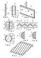
- the element as e.g. is shown particularly clearly in FIG. 1 or 2, has a permeable wall 1.
- This wall is based on a support grid 19.
- the support grid 19 itself can form an interior space 4 which is delimited by the wall 1.
- FIG. 2 shows the further possibility where the interior 4 of the element is formed between two supporting grid structures.
- the supporting structure of the support grid can be formed from braids that have an internal permeability, and if they are covered with walls at the interfaces to a fluid flow, the supporting structures must have at least three times larger central passage openings than the material of the Has wall to allow a flow of the fluid through the interior 4.
- FIG. 1 it is an element that is built in the form of a lamella.
- FIG. 2 it can be an element that is built in the form of a plate or in the form of a tube.
- the element is shaped such that it alone forms a turbulence generator 8, as can be seen, for example, in FIGS. 5 and 6.
- the shape of the element shown in FIG. 5 or in FIG. 6 is a single corrugated plate which can possibly act as a turbulence generator.
- Such a single corrugated lamella or also corrugated plate can be seen in perspective in FIG. 7.
- FIGS. 10, 11, 12 and 13 Examples of such elements according to the invention assembled into static mixers are shown in FIGS. 10, 11, 12 and 13.
- the static mixer 8, according to FIG. 11, is assembled by elements according to the invention in the form of tubes. The tubes in the individual layers 16 of the mixer 8 cross each other.
- the turbulence generator 8 which is shown in FIG. 13, is composed of lamellar elements 9 which are corrugated.
- the element with the permeable wall 1 is arranged in a vessel 3 which receives a fluid flow, which is indicated by arrows 2.
- the wall 1 is permeable to at least one component of the fluid and delimits an interior 4 of the element. This is connected to a space 5 outside the vessel 3 through the vessel wall 10. This is best shown with reference to FIG. 3, where the interior 4 is connected by means of lines 11 through the vessel wall 10 to the space 5 located outside the vessel 3.
- FIG. 6 which together with FIG. 5 shows a corrugated element installed in a pipe section 10, the interior 4 of which opens directly through the wall 10 of the tubular vessel 3 into a space 5 outside the vessel 3.
- the wall is only permeable to a component of the fluid flow 2 in the vessel 3, which as a filtrate through the wall 1 and through the interior 4 in cross flow into the space 5 outside the vessel 3 flows.
- the wall 1 is permeable to such a fluid, which then flows from the space 5 outside the vessel 3 through the interior 4 and through the wall 1 in a cross flow to be mixed into the fluid stream 2 in the vessel 3. Described with reference to FIG. 3, the fluid to be mixed would come from the space 5 through the tubular connecting parts 11 into the interior 4 and flows in a cross flow through the wall 1 into the fluid flow 2 in the vessel 3, to which it is added.
- the wall 1 can have at least one layer of material layer, the permeability of which is so large, or the pores of which are dimensioned such that the wall has the filtration function of the element in the Can exert micro to ultrafiltration range.
- the material layer layer mentioned could be a semipermeable membrane.
- the element as shown in Figures 5, 7, 13, 14, can have a shape of a plate or a film which is corrugated. If possible, such a curved plate or film itself can act as a turbulence generator in the form of a static mixer, as is particularly clearly shown in FIG. In another case, which is shown schematically in FIG. 13, a number of such corrugated elements are assembled to form a turbulence generator 8 in the form of a static mixer, in such a way that the troughs of the individual elements 9, 15 placed side by side run transversely to one another .
- connection of the interior 4 can, as shown in FIG. 6, open directly through the wall 10 of the vessel into a space 5 outside the vessel. This is the case shown in Figures 5 and 6.
- FIG. 3 It is also possible and shown in FIG. 3 that the interior 4 is connected to the space 5 outside the vessel 3 by means of a line piece 11 which penetrates the permeable wall 1 and the vessel wall 10.
- a space 5 is shown in FIG. 3 as a space which is delimited by a cylinder wall 22.
- FIG. 4 Another conceivable connection between the interior 4 and the space 5 outside the vessel is shown in FIG. 4, where the element is encased in a frame 13 which surrounds the interior all around and from which a connecting pipe piece 14 leads to a space 5.
- an opening through the wall 1 and through the interior 4, closed against this, 20 in FIG. 13, can lead through the element, so that the fluid flow 2 in the vessel 3 not only can flow along the wall 1 of the element, but also through it, and thus can change its direction not only along the element but also through the element.
- these penetrating openings 20 can be tubular. They can also have other shapes, e.g. be slot-shaped, as shown in the example of FIG. 11, where the tubular elements are provided with slots 12.
- the layer of material layer which is to enable the micro- to ultrafiltration of the element can be a layer of polysulfone which is applied to a support grid 19 sintered together from several layers and is impregnated therein.
- the interior 4 is provided with the permeable wall 1 only from one side.
- the other side of the Interior 4 can be limited by an impermeable wall.
- corrugated, lamellar elements can be placed next to one another parallel to one another, with the lamellae in a first section being in a position that is 90 relative to the position of the lamellae in the immediately following section of the turbulence generator ° are offset in space.
- turbulence generators are used to keep the cultivation fluid bed in constant mixing and to prevent uncontrollable swirling in the fluid bed or repeated mixing of elements that have previously been separated from one another.
- a fluid can be guided from the space 5 outside the reaction vessel through the elements assembled into turbulence generators 8 according to the invention, for example in order to gas the fluid bed in this way.
- FIG. 14 A possible method for manufacturing a device is to be explained on the basis of FIG. 14, where an element according to the invention is installed with the wall and the interior in a tubular vessel. The procedure is then that the lamellar element is first corrugated and then inserted into a tube of a larger diameter than the finished vessel should have. The element is inserted in this tube with a diameter D 3 in FIG. 4 in such a way that its interior points radially outward in cross section. This tube in which the element is inserted is rotated. A hardenable resin material is poured into this tube, which forms a layer on the rotating inner wall that encompasses the edges of the inserted element. After the cast plastic has hardened, the pipe produced with it is removed from the sleeve with the enclosed element.
- the interior 4 on the wall 10 would have to be sealed at a point 17 against the fluid flow 2. It is shown that the vessel 3 with its vessel wall 10 is inserted in a larger tube 22, between which and the wall 10 a space 5 that lies outside the space of the vessel 3 can be seen. In this case, the interior 4 is connected by means of the line pieces 11 which penetrate the wall 1 and the vessel wall 10.
Landscapes
- Chemical & Material Sciences (AREA)
- Chemical Kinetics & Catalysis (AREA)
- Organic Chemistry (AREA)
- Dispersion Chemistry (AREA)
- Physics & Mathematics (AREA)
- Thermal Sciences (AREA)
- Engineering & Computer Science (AREA)
- Manufacturing & Machinery (AREA)
- Separation Using Semi-Permeable Membranes (AREA)
- Filtering Materials (AREA)
- Cell Separators (AREA)
- Filtration Of Liquid (AREA)
Priority Applications (1)
| Application Number | Priority Date | Filing Date | Title |
|---|---|---|---|
| AT86115521T ATE60523T1 (de) | 1985-11-22 | 1986-11-08 | Element mit permeabler wandung. |
Applications Claiming Priority (2)
| Application Number | Priority Date | Filing Date | Title |
|---|---|---|---|
| CH4993/85 | 1985-11-22 | ||
| CH4993/85A CH670573A5 (fr) | 1985-11-22 | 1985-11-22 |
Publications (2)
| Publication Number | Publication Date |
|---|---|
| EP0226788A1 true EP0226788A1 (fr) | 1987-07-01 |
| EP0226788B1 EP0226788B1 (fr) | 1991-01-30 |
Family
ID=4286086
Family Applications (1)
| Application Number | Title | Priority Date | Filing Date |
|---|---|---|---|
| EP86115521A Expired - Lifetime EP0226788B1 (fr) | 1985-11-22 | 1986-11-08 | Elément à paroi perméable |
Country Status (7)
| Country | Link |
|---|---|
| US (1) | US4902418A (fr) |
| EP (1) | EP0226788B1 (fr) |
| JP (1) | JPS62125807A (fr) |
| AT (1) | ATE60523T1 (fr) |
| CA (1) | CA1292170C (fr) |
| CH (1) | CH670573A5 (fr) |
| DE (1) | DE3677352D1 (fr) |
Cited By (3)
| Publication number | Priority date | Publication date | Assignee | Title |
|---|---|---|---|---|
| EP0947239A3 (fr) * | 1998-03-27 | 2000-07-12 | Bayer Ag | Mélangeur statique |
| WO2008116872A1 (fr) * | 2007-03-27 | 2008-10-02 | Rwth Aachen | Dispositif à membrane et procédé de fabrication d'un dispositif à membrane |
| DE102020102420A1 (de) | 2020-01-31 | 2021-08-05 | Rwth Aachen | Gas-Flüssig-Reaktor zur blasenfreien Begasung einer Prozessflüssigkeit |
Families Citing this family (31)
| Publication number | Priority date | Publication date | Assignee | Title |
|---|---|---|---|---|
| JP2686078B2 (ja) * | 1987-07-16 | 1997-12-08 | 久夫 小嶋 | ミキシングエレメント |
| FI82670C (fi) * | 1989-01-27 | 1991-04-10 | Kemira Oy | Foerfarande foer framstaellning av vaeteperoxid. |
| CH678154A5 (fr) * | 1989-04-26 | 1991-08-15 | Robert Andreae | |
| US5312185A (en) * | 1989-12-28 | 1994-05-17 | Hisao Kojima | Motionless mixer and method for manufacturing the same |
| US5476783A (en) * | 1992-03-23 | 1995-12-19 | Koch Engineering Company, Inc. | Bioreactor method of culturing and propagating cells with a woven motionless mixing element |
| US5407274A (en) * | 1992-11-27 | 1995-04-18 | Texaco Inc. | Device to equalize steam quality in pipe networks |
| US5709468A (en) * | 1992-11-27 | 1998-01-20 | Texaco Group, Inc. | Method for equalizing steam quality in pipe networks |
| KR19990028592A (ko) | 1995-06-30 | 1999-04-15 | 와이너 길버트 피. | 분리장치 및 방법 |
| MXPA00011506A (es) * | 1998-05-23 | 2002-04-24 | Enersyst Dev Ct Llc | Horno de conveccion con velocidad de transferencia termica elevada con capacidades de manejo de grasa y reduccion de humo. |
| ID28054A (id) * | 1998-05-29 | 2001-05-03 | Abb Lummus Global Inc | Paking berstruktur dan elemen untuk itu |
| US6273938B1 (en) * | 1999-08-13 | 2001-08-14 | 3M Innovative Properties Company | Channel flow filter |
| GB9923626D0 (en) * | 1999-10-07 | 1999-12-08 | Univ Newcastle | Novel porous element and use thereof |
| US6667017B2 (en) | 1999-10-15 | 2003-12-23 | Abb Lummus Global, Inc. | Process for removing environmentally harmful compounds |
| CN1187113C (zh) * | 1999-10-15 | 2005-02-02 | Abb拉默斯环球有限公司 | 在负载于筛状结构的催化剂参与下氮的氧化物的转化 |
| DE10055785A1 (de) * | 2000-11-10 | 2002-06-06 | Gummi Jaeger Kg Gmbh & Cie | Vorrichtung zum Belüften von Wasser |
| GB0316864D0 (en) * | 2003-07-18 | 2003-08-20 | Linertech Ltd | Improvements in and relating to container liners |
| US7467523B2 (en) * | 2003-08-26 | 2008-12-23 | Aqwest, Llc | Autonomous water source |
| US7363769B2 (en) * | 2005-03-09 | 2008-04-29 | Kelix Heat Transfer Systems, Llc | Electromagnetic signal transmission/reception tower and accompanying base station employing system of coaxial-flow heat exchanging structures installed in well bores to thermally control the environment housing electronic equipment within the base station |
| CA2543317C (fr) * | 2005-04-25 | 2012-02-28 | Ronald D. Watt | Diffuseur d'air en bois utilisable dans les fractionnateurs a l'aide d'une mousse pour oceanariums |
| CA2584955C (fr) * | 2006-05-15 | 2014-12-02 | Sulzer Chemtech Ag | Melangeur statique |
| US7905358B2 (en) * | 2006-07-07 | 2011-03-15 | Alliant Techsystems Inc. | Apparatus and methods for filtering granular solid material |
| GB0621388D0 (en) * | 2006-10-27 | 2006-12-06 | Rolls Royce Plc | A support matrix arrangement |
| US9885154B2 (en) | 2009-01-28 | 2018-02-06 | Donaldson Company, Inc. | Fibrous media |
| CH701558A2 (de) | 2009-07-31 | 2011-01-31 | Alex Knobel | Vorrichtung und Verfahren zum Mischen und Austauschen von Fluiden. |
| JP5629556B2 (ja) * | 2010-11-10 | 2014-11-19 | ダイムラー・アクチェンゲゼルシャフトDaimler AG | 濾過構造 |
| WO2012103280A1 (fr) | 2011-01-28 | 2012-08-02 | Donaldson Company, Inc. | Procédé et appareil de formation d'un support fibreux |
| US9303339B2 (en) | 2011-01-28 | 2016-04-05 | Donaldson Company, Inc. | Method and apparatus for forming a fibrous media |
| KR101320467B1 (ko) * | 2011-10-26 | 2013-10-22 | 주식회사 부강테크 | 고정형 카오스 유동 유도체를 구비하는 여과장치 |
| US9713893B2 (en) * | 2013-07-09 | 2017-07-25 | Wenger Manufacturing, Inc. | Method of preconditioning comestible materials using steam/water static mixer |
| JP2016014381A (ja) * | 2014-07-03 | 2016-01-28 | ナブテスコ株式会社 | 車両用空気圧縮装置 |
| WO2018235210A1 (fr) * | 2017-06-21 | 2018-12-27 | エム・テクニック株式会社 | Module de membrane de filtration et procédé de filtration |
Citations (7)
| Publication number | Priority date | Publication date | Assignee | Title |
|---|---|---|---|---|
| FR1093157A (fr) * | 1953-02-11 | 1955-05-02 | Lorraine Carbone | Appareil pour la mise en contact de gaz ou de vapeurs avec des liquides |
| GB1298072A (en) * | 1969-06-18 | 1972-11-29 | Apv Co Ltd | Improvements in or relating to the treatment of liquids |
| FR2134377A1 (fr) * | 1971-04-29 | 1972-12-08 | Sulzer Ag | |
| FR2231408A1 (fr) * | 1973-05-29 | 1974-12-27 | Bentley Lab | |
| FR2271857A1 (fr) * | 1974-05-24 | 1975-12-19 | Johnson & Johnson | |
| US4207182A (en) * | 1975-11-14 | 1980-06-10 | Rhone-Poulenc Industries | Polymeric compositions for membranes |
| GB1592771A (en) * | 1977-09-15 | 1981-07-08 | Bellhouse F H | Apparatus for heat or mass transfer |
Family Cites Families (18)
| Publication number | Priority date | Publication date | Assignee | Title |
|---|---|---|---|---|
| US3051462A (en) * | 1959-03-12 | 1962-08-28 | Anthony A Fennell | Method and means for operating a soaking pit |
| US3190618A (en) * | 1963-04-30 | 1965-06-22 | Katzen Raphael | Fluid mixer |
| US3491021A (en) * | 1967-10-18 | 1970-01-20 | Morgan G Huntington | Method and apparatus for non-cyclic concentration of solution-suspension |
| US3620895A (en) * | 1969-01-03 | 1971-11-16 | Polaroid Corp | Corrugated micropermeable membrane |
| US3616928A (en) * | 1969-10-02 | 1971-11-02 | Du Pont | Permeation separation device for separating fluids |
| US3774771A (en) * | 1971-12-09 | 1973-11-27 | Interior | Reverse osmosis module |
| CH563802A5 (fr) * | 1973-04-18 | 1975-07-15 | Sulzer Ag | |
| FR2231787B1 (fr) * | 1973-06-01 | 1977-02-11 | Rhone Poulenc Ind | |
| US4043539A (en) * | 1975-03-28 | 1977-08-23 | Texaco Inc. | Method and apparatus for static type fluid mixing |
| DE2722025A1 (de) * | 1977-05-16 | 1978-11-30 | Hoechst Ag | Membraneinheit, vorrichtung mit membraneinheit und verfahren zur blutreinigung |
| SE7812682L (sv) * | 1978-01-05 | 1979-07-06 | Kuesters Eduard | Filteranordning |
| US4261834A (en) * | 1978-05-18 | 1981-04-14 | Millipore Corporation | Device and process for removing pyrogens from aqueous solutions |
| ZA796243B (en) * | 1978-11-22 | 1980-11-26 | B Bellhouse | Transfer membrane apparatus |
| EP0048730A1 (fr) * | 1980-03-24 | 1982-04-07 | Baxter Travenol Laboratories, Inc. | Dispositif de diffusion par canaux tubulaires ayant des guides d'ecoulement internes |
| FR2505204B1 (fr) * | 1981-05-05 | 1985-09-27 | Alsthom Atlantique | Dispositif pour le melange de fluides en circulation |
| JPS57209604A (en) * | 1981-06-19 | 1982-12-23 | Daicel Chem Ind Ltd | Separator element of membrane |
| US4636310A (en) * | 1982-12-07 | 1987-01-13 | Bellhouse Brian John | Transfer membrane apparatus |
| JPS6140725A (ja) * | 1984-07-31 | 1986-02-27 | 江口 節子 | 気泡による動力源装置 |
-
1985
- 1985-11-22 CH CH4993/85A patent/CH670573A5/de not_active IP Right Cessation
-
1986
- 1986-10-27 JP JP61255542A patent/JPS62125807A/ja active Pending
- 1986-11-06 US US06/927,849 patent/US4902418A/en not_active Expired - Lifetime
- 1986-11-08 AT AT86115521T patent/ATE60523T1/de not_active IP Right Cessation
- 1986-11-08 EP EP86115521A patent/EP0226788B1/fr not_active Expired - Lifetime
- 1986-11-08 DE DE8686115521T patent/DE3677352D1/de not_active Expired - Lifetime
- 1986-11-21 CA CA000523513A patent/CA1292170C/fr not_active Expired - Lifetime
Patent Citations (7)
| Publication number | Priority date | Publication date | Assignee | Title |
|---|---|---|---|---|
| FR1093157A (fr) * | 1953-02-11 | 1955-05-02 | Lorraine Carbone | Appareil pour la mise en contact de gaz ou de vapeurs avec des liquides |
| GB1298072A (en) * | 1969-06-18 | 1972-11-29 | Apv Co Ltd | Improvements in or relating to the treatment of liquids |
| FR2134377A1 (fr) * | 1971-04-29 | 1972-12-08 | Sulzer Ag | |
| FR2231408A1 (fr) * | 1973-05-29 | 1974-12-27 | Bentley Lab | |
| FR2271857A1 (fr) * | 1974-05-24 | 1975-12-19 | Johnson & Johnson | |
| US4207182A (en) * | 1975-11-14 | 1980-06-10 | Rhone-Poulenc Industries | Polymeric compositions for membranes |
| GB1592771A (en) * | 1977-09-15 | 1981-07-08 | Bellhouse F H | Apparatus for heat or mass transfer |
Cited By (5)
| Publication number | Priority date | Publication date | Assignee | Title |
|---|---|---|---|---|
| EP0947239A3 (fr) * | 1998-03-27 | 2000-07-12 | Bayer Ag | Mélangeur statique |
| US7390121B2 (en) | 1998-03-27 | 2008-06-24 | Bayer Aktiengesellschaft | Static mixer module |
| WO2008116872A1 (fr) * | 2007-03-27 | 2008-10-02 | Rwth Aachen | Dispositif à membrane et procédé de fabrication d'un dispositif à membrane |
| DE102020102420A1 (de) | 2020-01-31 | 2021-08-05 | Rwth Aachen | Gas-Flüssig-Reaktor zur blasenfreien Begasung einer Prozessflüssigkeit |
| US12319900B2 (en) | 2020-01-31 | 2025-06-03 | Rheinisch-Westfälische Technische Hochschule (Rwth) Aachen | Integral gas-introduction and stirring unit for gas-liquid reactors |
Also Published As
| Publication number | Publication date |
|---|---|
| US4902418A (en) | 1990-02-20 |
| ATE60523T1 (de) | 1991-02-15 |
| EP0226788B1 (fr) | 1991-01-30 |
| CA1292170C (fr) | 1991-11-19 |
| DE3677352D1 (de) | 1991-03-07 |
| JPS62125807A (ja) | 1987-06-08 |
| CH670573A5 (fr) | 1989-06-30 |
Similar Documents
| Publication | Publication Date | Title |
|---|---|---|
| EP0226788B1 (fr) | Elément à paroi perméable | |
| DE69510661T2 (de) | Verwendung von biofilmträger für wasser- und abwasser-reinigung | |
| EP0892670B1 (fr) | Dispositif de filtrage et de separation de fluides en mouvement | |
| DE69320954T2 (de) | Wasserklärvorrichtung mit isolierung des ersten filtrats verbesserter rückspülung und blasenbildung | |
| EP0002422B1 (fr) | Dispositif pour la filtration | |
| EP0819101A1 (fr) | Installation et procede d'oxydation d'une substance aqueuse | |
| DE3803886C2 (fr) | ||
| DE3783667T2 (de) | Trennvorrichtung mit spiralfoermig gewickelter membran und verfahren zu ihrer anwendung. | |
| DE1709333A1 (de) | Packungsmaterial fuer belueftete Filter biologischer Abwasserreinigungsanlagen | |
| DE10106722A1 (de) | Spezielles Hohlfaser-Membranmodul für den Einsatz in stark durch fouling beeinträchtigten Prozessen und seine Herstellung | |
| DE2324000B2 (de) | Vorrichtung zur biologischen Reinigung von Abwasser | |
| DE2231868B2 (de) | Zelle zur Duchführung der umgekehrten Osmose | |
| DE2753788A1 (de) | Vorrichtung zum zerstaeuben und dispergieren von fluida | |
| EP1166861A1 (fr) | Mélangeur pour mélanger au moins deux courants de gaz ou d'autres liquides newtoniens | |
| DE3916744A1 (de) | Rohrfoermiges filterelement | |
| EP0521495A2 (fr) | Procédé et appareil de fabrication de modules à fibres creuses | |
| EP0018511A1 (fr) | Substance réactive de remplissage ayant des propriétés d'échange | |
| DE19860942C1 (de) | Vorrichtung zur aeroben mikrobiologischen Aufbereitung von Abwasser | |
| DE102017001542A1 (de) | Verfahren zum Betrieb einer Filtrationsanlage | |
| DE2508867B2 (de) | Vorrichtung zum Wärme- oder Stoffaustausch, die aus mehreren durch parallele Platten gebildete Austauschräumen besteht | |
| DE10010387A1 (de) | Kompositmembran und Kompositmembransystem sowie Verfahren zur Herstellung der Kompositmembranen | |
| DE69926256T2 (de) | Monolitischer, poröser träger für filterelement und filterelement | |
| DE69712453T2 (de) | Vorrichtung zur Behandlung von organischen Abwasser mit Hilfe von Mikroorganismen | |
| EP2470291B9 (fr) | Module de fibres creuses tressées tridimensionnelles pour échanges de matière et d'énergie | |
| DE2529977B2 (de) | Vorrichtung mit Membranen auf rohrförmigen Abstützungen zum Behandeln von Fluiden |
Legal Events
| Date | Code | Title | Description |
|---|---|---|---|
| PUAI | Public reference made under article 153(3) epc to a published international application that has entered the european phase |
Free format text: ORIGINAL CODE: 0009012 |
|
| AK | Designated contracting states |
Kind code of ref document: A1 Designated state(s): AT BE DE FR GB IT LU NL SE |
|
| 17P | Request for examination filed |
Effective date: 19870825 |
|
| 17Q | First examination report despatched |
Effective date: 19881028 |
|
| GRAA | (expected) grant |
Free format text: ORIGINAL CODE: 0009210 |
|
| ITF | It: translation for a ep patent filed | ||
| AK | Designated contracting states |
Kind code of ref document: B1 Designated state(s): AT BE DE FR GB IT LU NL SE |
|
| REF | Corresponds to: |
Ref document number: 60523 Country of ref document: AT Date of ref document: 19910215 Kind code of ref document: T |
|
| REF | Corresponds to: |
Ref document number: 3677352 Country of ref document: DE Date of ref document: 19910307 |
|
| ET | Fr: translation filed | ||
| GBT | Gb: translation of ep patent filed (gb section 77(6)(a)/1977) | ||
| PLBE | No opposition filed within time limit |
Free format text: ORIGINAL CODE: 0009261 |
|
| STAA | Information on the status of an ep patent application or granted ep patent |
Free format text: STATUS: NO OPPOSITION FILED WITHIN TIME LIMIT |
|
| 26N | No opposition filed | ||
| REG | Reference to a national code |
Ref country code: GB Ref legal event code: 732E |
|
| REG | Reference to a national code |
Ref country code: FR Ref legal event code: TP |
|
| PGFP | Annual fee paid to national office [announced via postgrant information from national office to epo] |
Ref country code: LU Payment date: 19930917 Year of fee payment: 8 |
|
| PGFP | Annual fee paid to national office [announced via postgrant information from national office to epo] |
Ref country code: FR Payment date: 19930928 Year of fee payment: 8 |
|
| PGFP | Annual fee paid to national office [announced via postgrant information from national office to epo] |
Ref country code: GB Payment date: 19931101 Year of fee payment: 8 |
|
| PGFP | Annual fee paid to national office [announced via postgrant information from national office to epo] |
Ref country code: BE Payment date: 19931112 Year of fee payment: 8 |
|
| PGFP | Annual fee paid to national office [announced via postgrant information from national office to epo] |
Ref country code: SE Payment date: 19931126 Year of fee payment: 8 |
|
| PGFP | Annual fee paid to national office [announced via postgrant information from national office to epo] |
Ref country code: NL Payment date: 19931130 Year of fee payment: 8 Ref country code: AT Payment date: 19931130 Year of fee payment: 8 |
|
| NLS | Nl: assignments of ep-patents |
Owner name: CHEMAP AG TE VOLKETSWIL, ZWITSERLAND. |
|
| EPTA | Lu: last paid annual fee | ||
| PGFP | Annual fee paid to national office [announced via postgrant information from national office to epo] |
Ref country code: DE Payment date: 19931216 Year of fee payment: 8 |
|
| PG25 | Lapsed in a contracting state [announced via postgrant information from national office to epo] |
Ref country code: LU Free format text: LAPSE BECAUSE OF NON-PAYMENT OF DUE FEES Effective date: 19941108 Ref country code: GB Effective date: 19941108 Ref country code: AT Effective date: 19941108 |
|
| PG25 | Lapsed in a contracting state [announced via postgrant information from national office to epo] |
Ref country code: SE Effective date: 19941109 |
|
| PG25 | Lapsed in a contracting state [announced via postgrant information from national office to epo] |
Ref country code: BE Effective date: 19941130 |
|
| EAL | Se: european patent in force in sweden |
Ref document number: 86115521.6 |
|
| BERE | Be: lapsed |
Owner name: GEBRUDER SULZER A.G. Effective date: 19941130 |
|
| PG25 | Lapsed in a contracting state [announced via postgrant information from national office to epo] |
Ref country code: NL Effective date: 19950601 |
|
| GBPC | Gb: european patent ceased through non-payment of renewal fee |
Effective date: 19941108 |
|
| NLV4 | Nl: lapsed or anulled due to non-payment of the annual fee | ||
| PG25 | Lapsed in a contracting state [announced via postgrant information from national office to epo] |
Ref country code: FR Effective date: 19950731 |
|
| PG25 | Lapsed in a contracting state [announced via postgrant information from national office to epo] |
Ref country code: DE Effective date: 19950801 |
|
| EUG | Se: european patent has lapsed |
Ref document number: 86115521.6 |
|
| REG | Reference to a national code |
Ref country code: FR Ref legal event code: ST |
|
| PG25 | Lapsed in a contracting state [announced via postgrant information from national office to epo] |
Ref country code: IT Free format text: LAPSE BECAUSE OF NON-PAYMENT OF DUE FEES;WARNING: LAPSES OF ITALIAN PATENTS WITH EFFECTIVE DATE BEFORE 2007 MAY HAVE OCCURRED AT ANY TIME BEFORE 2007. THE CORRECT EFFECTIVE DATE MAY BE DIFFERENT FROM THE ONE RECORDED. Effective date: 20051108 |