EP0226812A2 - Deaktivierbares Sicherungsetikett für Diebstahlsicherungssysteme - Google Patents
Deaktivierbares Sicherungsetikett für Diebstahlsicherungssysteme Download PDFInfo
- Publication number
- EP0226812A2 EP0226812A2 EP86115899A EP86115899A EP0226812A2 EP 0226812 A2 EP0226812 A2 EP 0226812A2 EP 86115899 A EP86115899 A EP 86115899A EP 86115899 A EP86115899 A EP 86115899A EP 0226812 A2 EP0226812 A2 EP 0226812A2
- Authority
- EP
- European Patent Office
- Prior art keywords
- strip
- security label
- field strength
- soft magnetic
- coercive field
- Prior art date
- Legal status (The legal status is an assumption and is not a legal conclusion. Google has not performed a legal analysis and makes no representation as to the accuracy of the status listed.)
- Granted
Links
Images


Classifications
-
- G—PHYSICS
- G08—SIGNALLING
- G08B—SIGNALLING SYSTEMS, e.g. PERSONAL CALLING SYSTEMS; ORDER TELEGRAPHS; ALARM SYSTEMS
- G08B13/00—Burglar, theft or intruder alarms
- G08B13/22—Electrical actuation
- G08B13/24—Electrical actuation by interference with electromagnetic field distribution
- G08B13/2402—Electronic Article Surveillance [EAS], i.e. systems using tags for detecting removal of a tagged item from a secure area, e.g. tags for detecting shoplifting
- G08B13/2405—Electronic Article Surveillance [EAS], i.e. systems using tags for detecting removal of a tagged item from a secure area, e.g. tags for detecting shoplifting characterised by the tag technology used
- G08B13/2408—Electronic Article Surveillance [EAS], i.e. systems using tags for detecting removal of a tagged item from a secure area, e.g. tags for detecting shoplifting characterised by the tag technology used using ferromagnetic tags
- G08B13/2411—Tag deactivation
-
- G—PHYSICS
- G01—MEASURING; TESTING
- G01V—GEOPHYSICS; GRAVITATIONAL MEASUREMENTS; DETECTING MASSES OR OBJECTS; TAGS
- G01V15/00—Tags attached to, or associated with, an object, in order to enable detection of the object
-
- G—PHYSICS
- G08—SIGNALLING
- G08B—SIGNALLING SYSTEMS, e.g. PERSONAL CALLING SYSTEMS; ORDER TELEGRAPHS; ALARM SYSTEMS
- G08B13/00—Burglar, theft or intruder alarms
- G08B13/22—Electrical actuation
- G08B13/24—Electrical actuation by interference with electromagnetic field distribution
- G08B13/2402—Electronic Article Surveillance [EAS], i.e. systems using tags for detecting removal of a tagged item from a secure area, e.g. tags for detecting shoplifting
- G08B13/2428—Tag details
- G08B13/2437—Tag layered structure, processes for making layered tags
-
- G—PHYSICS
- G08—SIGNALLING
- G08B—SIGNALLING SYSTEMS, e.g. PERSONAL CALLING SYSTEMS; ORDER TELEGRAPHS; ALARM SYSTEMS
- G08B13/00—Burglar, theft or intruder alarms
- G08B13/22—Electrical actuation
- G08B13/24—Electrical actuation by interference with electromagnetic field distribution
- G08B13/2402—Electronic Article Surveillance [EAS], i.e. systems using tags for detecting removal of a tagged item from a secure area, e.g. tags for detecting shoplifting
- G08B13/2428—Tag details
- G08B13/2437—Tag layered structure, processes for making layered tags
- G08B13/2442—Tag materials and material properties thereof, e.g. magnetic material details
-
- Y—GENERAL TAGGING OF NEW TECHNOLOGICAL DEVELOPMENTS; GENERAL TAGGING OF CROSS-SECTIONAL TECHNOLOGIES SPANNING OVER SEVERAL SECTIONS OF THE IPC; TECHNICAL SUBJECTS COVERED BY FORMER USPC CROSS-REFERENCE ART COLLECTIONS [XRACs] AND DIGESTS
- Y10—TECHNICAL SUBJECTS COVERED BY FORMER USPC
- Y10S—TECHNICAL SUBJECTS COVERED BY FORMER USPC CROSS-REFERENCE ART COLLECTIONS [XRACs] AND DIGESTS
- Y10S428/00—Stock material or miscellaneous articles
- Y10S428/922—Static electricity metal bleed-off metallic stock
- Y10S428/9265—Special properties
- Y10S428/928—Magnetic property
Definitions
- the invention relates to a deactivatable security tag for anti-theft systems, in which a soft magnetic strip can change a magnetic alternating field generated in a test zone and thus trigger an alarm, consisting of at least two strips of ferromagnetic material arranged close to one another, at least one of which is made of soft magnetic material with high permeability and low coercive field strength, while at least one further strip has a higher coercive field strength and can be magnetized in such a way that the stray field which arises penetrates the strip of soft magnetic material in sections in opposite directions.
- Such an anti-theft system is described, for example, in US Pat. No. 3,820,104.
- a narrow, soft magnetic strip is arranged in the vicinity of a substantially wider strip made of a magnetic material with a higher coercive field strength. If this arrangement is brought into a zone with an alternating magnetic field, the soft magnetic strip changes this alternating field and induces voltage harmonics in a coil influenced by the alternating field. Let pan Vietnamesesoberwellen this S is to trigger an alarm evaluate.
- a stray flux is generated through openings punched into these strips at intervals, which magnetizes the soft magnetic strip in sections in the opposite direction to one another.
- the soft magnetic strip is largely saturated, so that it produces no or other and significantly lower harmonics when it is brought into the alternating field. The strip is therefore deactivated and does not trigger an alarm.
- the security label consists of two or more strips arranged with one another with different coercive field strengths. To deactivate this label, one of the strips has a sufficient cross section to saturate the soft magnetic strip, so that the magnetic alternating field does not cause the strip to be remagnetized.
- an amorphous band is used as the soft magnetic material, which is connected to short strips of hard magnetic material which are arranged at a distance from one another.
- the magnetization of these hard magnetic strips produces differently pre-magnetized sections in the soft magnetic band, so that the soft magnetic material no longer generates harmonics which lead to the triggering of an alarm.
- the object of the present invention is to provide a security label which can be deactivated and which has as little magnetic material as possible and has a higher Koerzi active field strength and can be easily activated and deactivated.
- the security label consists of a single piece and can therefore be wound in a tape form on a roll, from which labels can be cut to the desired length and connected to the goods to be protected.
- the strips forming the security label are firmly connected to one another to form a laminate, in that the strip with a higher coercive field strength consists of a cobalt-based alloy which additionally contains nickel and / or iron and their coercive field strength in the range between 20 and 50 A.
- / cm is a remanent induction of more than 1 Tesla, and that a series of differently polarized magnets is used to deactivate the security label, which magnetizes the security label in opposite sections.
- FIG. 1 An exemplary embodiment of a deactivatable security tag according to the invention with associated deactivation device is shown schematically in FIG. 1.
- the security label consists of a strip 1 made of soft magnetic material with a high permeability and a lower coercive force and a strip 2 made of a magnetically semi-hard alloy containing cobalt, nickel and iron.
- the strips 1 and 2 are firmly connected to one another by a weld seam or by welding spots 3, for example with the aid of a resistance spot welding process, so that the security label 4 can be cut off piece by piece from a rolled-up tape.
- the welding points 3 connect the strips 1 and 2 so firmly that the shear forces that occur when the Security labels can be included.
- the welding spots are advantageously spaced from one another by between 10 and 50 mm. However, other cases are also conceivable in which a distance of 3 mm is required or in which the distance between two adjacent welding points 3 can be up to 500 mm.
- permanent magnets 5 for example made of CoSm, are applied to a plate 6 acting as a magnetic yoke in such a way that adjacent magnets 5 have opposite magnetization directions.
- the direction of magnetization of the magnets 5 is indicated by arrows, the lines 7 indicate some of the stray field lines generated by the magnets.
- the material used for the strips 2 with a higher coercive field strength offers the advantage for the security label according to the invention because of the low coercive field strength and the at the same time quite high remanence that a relatively small cross section (compared to the cross section of the soft magnetic strip 1) can be provided and that for deactivation Commercial permanent magnets can be used, since relatively low magnetic fields are sufficient to re-magnetize the material of the strips 2. This is especially true since the selected material has a much more rectangular magnetization loop than, for example, other magnet materials, so that the magnetization field strength does not have to be chosen significantly larger than the coercive field strength in order to achieve the maximum possible remanence.
- the strip 2 is uniformly magnetized, which in the alternating magnetic field only results in a temporal shift of the harmonics achieved, but not in a change in the intensity of these harmonics. Therefore, this method can be used to reactivate the strip without the need for a degaussing device. This can be seen, for example, from the diagrams in FIGS. 2a to 2c.
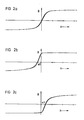
- Figure 2a shows the hysteresis curve of the security tag according to the invention in the event that the strip 2 is largely demagnetized. Assuming that the field strength of an alternating field influencing the strip fluctuates between +3 A / cm and -3 A / cm, strip 1 is remagnetized in the field of zero field strength, which results in voltage pulses, the cause of the generation of an alarm are triggering harmonics.
- FIGS. 2b and 2c If the security strip is magnetized in one direction or the other, the conditions result as shown in FIGS. 2b and 2c. It can be seen that the region of the magnetic reversal shifts to negative or positive values. This shows that the strip 1 is remagnetized even when the strip 2 is magnetized, the voltage pulses occurring in the alternating magnetic field only being shifted in time. If the security label 4 is deactivated in accordance with the arrangement according to FIG. 1, regions 2 with different magnetization directions are created in the strip, which result in a significantly higher stray field than if the entire strip 2 is magnetized in one direction. this has with the result that the strip 1 is no longer magnetized over its entire length under the same field influence as in FIG.
- one to five strips of the latter alloy with the dimensions 0.5 mm wide and 0.05 mm thick are glued onto an amorphous tape of a cobalt-based alloy with a width of 2.5 mm and a thickness of 0.025 mm. Deactivation was already possible when using 2 strips (effective total cross-section 1.0 x 0.05 mm); when using CoSm magnets and a distance between security label 4 and permanent magnet 5 of 5 mm and 8 mm.
- the above-mentioned, hard magnetic material was rolled to the dimensions 2.5 x 0.033 mm and by heating action set a coercive field strength of 46 A / cm in a first attempt and a coercive field strength of 20 A / cm in a second attempt.
- Each 10 meters was welded together with an amorphous, soft magnetic tape by spot welding.
- the band with 46 A / cm coercive field strength can be deactivated up to a distance of 5 mm from the permanent magnet 5 and the sample with a coercive field strength of 20 A / cm can be deactivated up to a distance of 9 mm.
- the permanent magnets 5 are advantageously at a distance of about 5 mm to 6 mm from one another. This distance was recognized as advantageous when the security label 4 was deactivated at a distance of 5 mm to 8 mm.
- the security label does not necessarily have to be oriented parallel to the row of permanent magnets. An oblique orientation is also possible. This results in only a slight change in the magnetization distribution. Safe deactivation was possible up to an oblique orientation of approximately 70 ° with respect to the parallel position shown in FIG. 1.
- strips 1 and 2 are not glued to one another, but rather are joined to one another by spot welding.
- the security label produced by spot welding was easily bendable at a distance of the welding points of 10 mm, so that normally larger welding point distances of up to 50 mm can also be expected to give good results.
Landscapes
- Physics & Mathematics (AREA)
- General Physics & Mathematics (AREA)
- Engineering & Computer Science (AREA)
- Automation & Control Theory (AREA)
- Computer Security & Cryptography (AREA)
- Electromagnetism (AREA)
- Life Sciences & Earth Sciences (AREA)
- General Life Sciences & Earth Sciences (AREA)
- Geophysics (AREA)
- Burglar Alarm Systems (AREA)
Abstract
Description
- Die Erfindung betrifft ein deaktivierbares Sicherungsetikett für Diebstahlsicherungssysteme, bei denen ein weichmagnetischer Streifen ein in einer Prüfzone erzeugtes magnetisches Wechselfeld verändern und damit einen Alarm auslösen kann, bestehend aus mindestens zwei nahe beieinander angeordneter, aus ferromagnetischem Material bestehender Streifen, von denen mindestens einer aus weichmagnetischem Material mit hoher Permeabilität und niedriger Koerzitivfeldstärke besteht, während mindestens ein weiterer Streifen eine höhere Koerzitivfeldstärke aufweist und so magnetisierbar ist, daß das sich einstellende Streufeld den Streifen aus weichmagnetischem Material abschnittweise in einander entgegengesetzten Richtungen durchsetzt.
- Ein derartiges Diebstahlsicherungssystem ist beispielsweise in der US-PS 3 820 104 beschrieben. Hier wird ein schmaler, weichmagnetischer Streifen in der Nähe eines wesentlich breiteren Streifens aus einem magnetischen Material mit höherer Koerzitivfeldstärke angeordnet. Wenn diese Anordnung in eine Zone mit einem magnetischen Wechselfeld gebracht wird, so ändert der weichmagnetische Streifen dieses Wechselfeld und induziert in einer vom Wechselfeld beeinflußten Spule Spannungsoberwellen. Diese Spannungsoberwellen lassen sich zur Auslösung eines Alarms auswerten.
- Will man dieses bekannte Sicherungsetikett deaktivieren, so kann man den breiteren magnetischen Streifen mit höherer Koerzitivfeldstärke in Längsrichtung magnetisieren.
- Durch in Abständen in diesen Streifen eingestanzte öffnungen wird ein Streufluß erzeugt, der den weichmagnetischen Streifen abschnittweise in einander entgegengesetzter Richtung aufmagnetisiert. In diesem Zustand ist der weichmagnetische Streifen weitgehend gesättigt, so daß er keine bzw. andere und wesentlich geringere Oberwellen erzeugt, wenn er in das Wechselfeld gebracht wird. Der Streifen ist also deaktiviert und löst keinen Alarm aus.
- Andere bekannte Anordnungen besitzen eine ähnliche Wirkungsweise. In der US-PS 3 747 086 besteht das Sicherungsetikett aus zwei oder mehreren beieinander angeordneten Streifen mit unterschiedlichen Koerzitivfeldstärken. Zur Deaktivierung dieses Etiketts besitzt einer der Streifen einen ausreichenden Querschnitt, um den weichmagnetischen Streifen zu sättigen, so daß durch das magnetische Wechselfeld keine Ummagnetisierung des Streifens erfolgt.
- Bei einer weiteren bekannten Anordnung, wie sie in der DE-OS 34 19 785 beschrieben ist, verwendet man als weichmagnetisches Material ein amorphes Band, das mit kurzen Streifen eines hartmagnetischen Materials, die im Abstand zueinander angeordnet sind, verbunden ist. Auch hier erzeugt die Magnetisierung dieser hartmagnetischen Streifen unterschiedlich vormagnetisierte Abschnitte im weichmagnetischen Band, so daß durch das weichmagnetische Material keine Oberwellen mehr erzeugt werden, die zur Auslösung eines Alarms führen.
- Aufgabe der vorliegenden Erfindung ist es, ein deaktivierbares Sicherungsetikett vorzusehen, das mit möglichst wenig Anteil an magnetischem Material mit höherer Koerzitivfeldstärke auskommt und leicht aktiviert und deaktiviert werden kann. Außerdem besteht das Sicherungsetikett aus einem einzigen Stück und kann deshalb in Bandform auf eine Rolle gewickelt vorliegen, von der Etiketten entsprechend der gewünschten Länge abgeschnitten und mit den zu schützenden Waren verbunden werden können.
- Diese Aufgabe wird erfindungsgemäß dadurch gelöst, daß die das Sicherungsetikett bildenden Streifen fest miteinander zu einem Laminat verbunden sind, daß der Streifen mit höherer Koerzitivfeldstärke aus einer Kobaltbasislegierung besteht, die zusätzlich Nickel und/oder Eisen enthält und deren Koerzitivfeldstärke im Bereich zwischen 20 und 50 A/cm liegt bei einer Remanenzinduktion von mehr als 1 Tesla, und daß zur Deaktivierung des Sicherungsetiketts eine Reihe unterschiedlich gepolter Magnete dient, die das Sicherungsetikett abschnittweise entgegengesetzt aufmagnetisiert.
- Ein Ausführunsbeispiel für ein erfindungsgemäßes, deaktivierbares Sicherungsetikett mit zugehöriger Deaktivierungseinrichtung ist in Figur 1 schematisch dargestellt.
- Das Sicherungsetikett besteht aus einem Streifen 1 aus weichmagnetischem Material mit hoher Permeabilität und niedrigerer Koerzitivfeldstärke sowie aus einem Streifen 2 aus einer magnetisch halbharten, Kobalt, Nickel und Eisen enthaltenden Legierung. Die Streifen 1 und 2 sind durch eine Schweißnaht oder durch Schweißpunkte 3, z.B. mit Hilfe eines Widerstandspunktschweißverfahrens, fest miteinander verbunden, so daß das Sicherungsetikett 4 von einem aufgerollten Band stückweise abgeschnitten werden kann. Die Schweißpunkte 3 verbinden die Streifen l und 2 so fest, daß die auftretenden Scherkräfte bei Biegung des Sicherungsetiketts aufgenommen werden können.
- Vorteilhafterweise besitzen die Schweißpunkte voneinander einen Abstand zwischen 10 und 50 mm. Es sind allerdings auch andere Fälle denkbar, bei denen ein Abstand von 3 mm erforderlich ist oder bei denen der Abstand zweier benachbarter Schweißpunkte 3 bis zu 500 mm betragen kann.
- Zur Deaktivierung sind Dauermagnete 5, beispielsweise aus CoSm, auf einer als magnetischer Rückschluß wirkenden Platte 6 so aufgebracht, daß benachbarte Magnete 5 zueinander entgegengesetzte Magnetisierungsrichtungen aufweisen. Die Magnetisierungsrichtung der Magnete 5 ist durch Pfeile angedeutet, die Linien 7 deuten einige der von den Magneten erzeugten Streufeldlinien an.
- Das verwendete Material für die Streifen 2 mit höherer Koerzitivfeldstärke bietet für das erfindungsgemäße Sicherungsetikett wegen der geringen Koerzitivfeldstärke und der gleichzeitig recht hohen Remanenz den Vorteil, daß ein relativ geringer Querschnitt (verglichen mit dem Querschnitt des weichmagnetischen Streifens 1) vorgesehen werden kann und daß zum Deaktivieren handelsübliche Dauermagnete verwendet werden können, da relativ niedrige Magnetfelder ausreichen, um das Material der Streifen 2, umzumagnetisieren. Dies gilt vor allem auch, da das gewählte Material eine wesentlich rechteckigere Magnetisierungsschleife besitzt als beispielsweise andere Magnetwerkstoffe, so daß die Magnetisierungsfeldstärke nicht wesentlich größer als die Koerzitivfeldstärke gewählt werden muß, um die maximal mögliche Remanenz zu erreichen.
- Wird der Streifen nicht in der in Figur 1 gezeigten Richtung in die Nähe der Dauermagnete 5 gebracht, sondern beispielsweise senkrecht dazu an einem der Dauermagnete 5 vorbeigeführt, so entsteht eine gleichmäßige Aufmagnetisierung des Streifens 2, die im magnetischen Wechselfeld lediglich eine zeitliche Verschiebung der erzielten Oberwellen, nicht aber eine Änderung der Intensität dieser Oberwellen zur Folge hat. Deshalb kann man dieses Verfahren zum Wiederaktivieren des Streifens benutzen, ohne daß eine Entmagnetisierungseinrichtung erforderlich ist. Dies ist beispielsweise aus den Diagrammen in den Figuren 2a bis 2c zu ersehen.
- Figur 2a zeigt die Hysteresekurve des erfindungsgemäßen Sicherungsetiketts für den Fall, daß der Streifen 2 weitgehend entmagnetisiert ist. Nimmt man an, daß die Feldstärke eines den Streifen beeinflussenden Wechselfeldes zwischen +3 A/cm und -3 A/cm schwankt, so wird im Bereich der Feldstärke Null der Streifen 1 ummagnetisiert, was Spannungsimpulse ergibt, die Ursache für die Erzeugung einer den Alarm auslösenden Oberwellen sind.
- Ist der Sicherungsstreifen in der einen oder anderen Richtung aufmagnetisiert, so ergeben sich die Verhältnisse, wie sie in den Figuren 2b und 2c dargestellt sind. Man erkennt, daß sich der Bereich der Ummagnetisierung nach negativen bzw. positiven Werten verschiebt. Dies zeigt, daß auch bei aufmagnetisiertem Streifen 2 eine Ummagnetisierung des Streifens 1 erfolgt, wobei die im magnetischen Wechselfeld auftretenden Spannungsimpulse lediglich zeitlich verschoben sind. Wird das Sicherungsetikett 4 entsprechend der Anordnung nach Figur 1 deaktiviert, so entstehen in dem Streifen 2 Bereiche mit unterschiedlichen Magnetisierungsrichtungen, die ein wesentlich höheres Streufeld zur Folge haben, als wenn der gesamte Streifen 2 in einer Richtung magnetisiert ist. Dies hat zur Folge, daß der Streifen 1 bei dem gleichen Feldeinfluß wie in Figur 2 nicht mehr in ganzer Länge ummagnetisiert wird.
- Dies ist in Figur 3 dargestellt. Es zeigt sich, daß sich die Induktion bei einer Feldänderung von +3 A/cm nach -3 A/cm kaum noch ändert. Die im Wechselfeld induzierte Oberwellenspannung wird drastisch vermindert. Ein Alarm wird nicht mehr ausgelöst.
- Versuche haben ergeben, daß folgende Legierungen als magnetisches Material für den Streifen 2 mit höherer Koerzitivfeldstärke in Verbindung mit einem Streifen aus amorphem Material geeignet sind:
- 12,0 % Eisen, 3,1 % Niob, 0,50 % Mangan, 0,20 % Silizium, Rest Kobalt.
- 58,1 % Kobalt, 10,0 % Nickel, 2,2 % Aluminium, 2,1 % Titan, Rest Eisen.
- 55,1 % Kobalt, 11,5 % Nickel, 3,0 % Titan, 1,2 % Aluminium, Rest Eisen.
- Beispielsweise werden ein bis fünf Streifen der letztgenannten Legierung mit der Abmessung 0,5 mm Breite und 0,05 mm Dicke auf ein amorphes Band einer Kobaltbasislegierung mit einer Breite von 2,5 mm und einer Dicke von 0,025 mm aufgeklebt. Schon bei Verwendung von 2 Streifen (effektiver Gesamtquerschnitt 1,0 x 0,05 mm) war eine Deaktivierung möglich; bei Verwendung von CoSm-Magneten und einem Abstand zwischen Sicherungsetikett 4 und Dauermagneten 5 von 5 mm und 8 mm.
- Weiterhin wurde das genannte, hartmagnetische Material auf die Abmessung 2,5 x 0,033 mm gewalzt und durch Wärmebehandlung bei einem ersten Versuch eine Koerzitivfeldstärke von 46 A/cm und einem zweiten Versuch eine Koerzitivfeldstärke von 20 A/cm eingestellt. Je 10 Meter wurden mit einem amorphen, weichmagnetischen Band durch Punktschweißen zusammengeschweißt. Bei dem Band mit 46 A/cm Koerzitivfeldstärke läßt sich eine Deaktivierung bis zu einem Abstand von 5 mm zum Dauermagneten 5 und bei der Probe mit einer Koerzitivfeldstärke von 20 A/cm läßt sich eine Deaktivierung bis zu einem Abstand von 9 mm vornehmen.
- Als Streifenlänge wurden bei den Versuchen 75 mm und 90 mm gewählt und hierbei eine ausreichende Ansprechsicherheit der Alarmanlage festgestellt. Die Dauermagnete 5 besitzen vorteilhafterweise einen Abstand von etwa 5 mm bis 6 mm voneinander. Dieser Abstand wurde bei einer Deaktivierung des Sicherungsetiketts 4 im Abstand von 5 mm bis 8 mm als vorteilhaft erkannt.
- Das Sicherungsetikett muß nicht unbedingt parallel zu der Reihe der Dauermagnete orientiert sein. Eine Schrägorientierung ist auch möglich. Hierdurch ergibt sich lediglich eine geringfügige Änderung der Magnetisierungsverteilung. Eine sichere Deaktivierung war bis zu einer Schrägorientierung von etwa 70° gegenüber der in Figur 1 dargestellten Parallellage möglich.
- Als besonders vorteilhaft hat es sich erwiesen, wenn die Streifen 1 und 2 nicht miteinander verklebt, sondern durch Punktschweißen miteinander verbunden wurden. Das durch Punktschweißen hergestellte Sicherungsetikett war bei einem Abstand der Schweißpunkte von 10 mm gut biegbar, so daß im Normalfall größere Schweißpunktabstände bis zu 50 mm ebenfalls gute Ergebnisse.erwarten lassen.
Claims (8)
dadurch gekennzeichnet,
daß die das Sicherungsetikett bildenden Streifen (1,2) fest miteinander zu einem Laminat verbunden sind, daß der Streifen (2) mit höherer Koerzitivfeldstärke aus einer Kobaltbasislegierung besteht, die zusätzlich Nickel und/oder Eisen enthält und deren Koerzitivfeldstärke im Bereich zwischen 20 und 50 A/cm liegt bei einer Remanenzinduktion von mehr als 1 Tesla, und daß zur Deaktivierung des Sicherungsetiketts eine Reihe unterschiedlich gepolter Magnete (5) dient, die das Sicherungsetikett abschnittweise entgegengesetzt aufmagnetisieren.
daß der Streifen (2) mit höherer Koerzitivfeldstärke aus einer Legierung mit 9 bis 15 Gew.-% Nickel, mehr als 50 Gew.-% Kobalt, Rest Eisen besteht, die bis zu 4 % Zusätze von Aluminium, Titan und Niob enthalten kann.
daß der Streifen (2) mit höherer Koerzitivfeldstärke aus einer Legierung mit 9 bis 12 Gew.-% Nickel, 54 bis 59 Gew.-% Kobalt, Rest Eisen und bis zu 3 Gew.-% Zusätze aus Aluminium und Titan besteht.
daß der weichmagnetische Streifen (1) aus einem amorph gegossenen Material besteht und an dem Streifen (2) mit höherer Koerzitivfeldstärke durch Punktschweißen befestigt ist.
daß der Abstand der Schweißpunkte (3) zwischen 3 mm und 500 mm beträgt.
daß der Abstand der Schweißpunkte (3) voneinander 10 mm bis 50 mm beträgt.
daß der weichmagnetische Streifen an dei Streifen mit höherer Koerzitivfeldstärke durch Nahts nweißen befestigt ist.
daß durch Wärmebehandlung der Legierung eine Koerzitivfeldstärke zwischen 20 und 50 A/cm bei einer Remanenz von mehr als 1,2 Tesla eingestellt ist.
Applications Claiming Priority (2)
| Application Number | Priority Date | Filing Date | Title |
|---|---|---|---|
| DE3545647 | 1985-12-21 | ||
| DE19853545647 DE3545647A1 (de) | 1985-12-21 | 1985-12-21 | Deaktivierbares sicherungsetikett fuer diebstahlsicherungssysteme |
Publications (3)
| Publication Number | Publication Date |
|---|---|
| EP0226812A2 true EP0226812A2 (de) | 1987-07-01 |
| EP0226812A3 EP0226812A3 (en) | 1989-03-22 |
| EP0226812B1 EP0226812B1 (de) | 1993-01-27 |
Family
ID=6289290
Family Applications (1)
| Application Number | Title | Priority Date | Filing Date |
|---|---|---|---|
| EP86115899A Expired - Lifetime EP0226812B1 (de) | 1985-12-21 | 1986-11-15 | Deaktivierbares Sicherungsetikett für Diebstahlsicherungssysteme |
Country Status (3)
| Country | Link |
|---|---|
| US (1) | US4743890A (de) |
| EP (1) | EP0226812B1 (de) |
| DE (2) | DE3545647A1 (de) |
Cited By (6)
| Publication number | Priority date | Publication date | Assignee | Title |
|---|---|---|---|---|
| EP0447793A3 (en) * | 1990-03-21 | 1991-12-18 | Vacuumschmelze Gmbh | Security label capable of deactivation |
| GB2299789A (en) * | 1995-03-24 | 1996-10-16 | Selectus Limited | Tape |
| EP0820044A3 (de) * | 1996-07-17 | 1998-09-23 | Meto International GmbH | Vorrichtung zum Deaktivieren eines Sicherungselementes für die elektronische Artikelsicherung |
| EP0895206A1 (de) * | 1997-07-29 | 1999-02-03 | Esselte Meto International GmbH | Sicherungselement für die elektronische Artikelsicherung |
| EP0961301A4 (de) * | 1997-11-17 | 2001-07-18 | Unitika Ltd | Magnetisches etikett |
| US6690279B1 (en) | 1998-07-22 | 2004-02-10 | Meto International Gmbh | Security element for the electronic surveillance of articles |
Families Citing this family (20)
| Publication number | Priority date | Publication date | Assignee | Title |
|---|---|---|---|---|
| US4829288A (en) * | 1987-11-30 | 1989-05-09 | Minnesota Mining And Manufacturing Company | Economic, multi-directionally responsive marker for use in electronic article surveillance systems |
| US5582924A (en) * | 1989-01-09 | 1996-12-10 | Esselte Meto International Gmbh | Magnetic materials for security applications |
| US5368948A (en) * | 1989-01-09 | 1994-11-29 | Esselte Meto International Produktions | Magnetic materials for security applications |
| US5015992A (en) * | 1989-06-29 | 1991-05-14 | Pitney Bowes Inc. | Cobalt-niobium amorphous ferromagnetic alloys |
| SE500627C2 (sv) * | 1990-03-20 | 1994-08-01 | Esselte Meto Int Gmbh | Handscanner anordnad att optiskt avläsa en streckkod på en vara |
| TW198154B (de) * | 1991-08-20 | 1993-01-11 | Allied Signal Inc | |
| AU3098592A (en) * | 1991-11-29 | 1993-06-28 | Maloe Nauchno-Proizvodstvennoe Predpriyatie "Lkt" | Magneto-optical method for testing articles |
| US5401584A (en) * | 1993-09-10 | 1995-03-28 | Knogo Corporation | Surveillance marker and method of making same |
| US5422167A (en) * | 1993-09-17 | 1995-06-06 | Infosight Corporation | High temperature-resistant, thermally-printable label for attachment to hot metal stock and method thereof |
| DE19521048A1 (de) * | 1995-06-09 | 1996-12-12 | Giesecke & Devrient Gmbh | Sicherheitsdokument und Verfahren zu seiner Herstellung |
| US5602528A (en) * | 1995-06-20 | 1997-02-11 | Marian Rubber Products Company, Inc. | Theft detection marker and method |
| RU2183033C2 (ru) * | 1995-07-17 | 2002-05-27 | Флайинг Налл Лимитед | Усовершенствования, относящиеся к магнитным ярлыкам или маркерам |
| FR2739194B1 (fr) * | 1995-09-21 | 1997-10-31 | Sermme Systemes Sarl | Procede et dispositif de protection d'articles contre le vol et leurs applications au pret automatise de livres |
| FR2746956B1 (fr) * | 1996-03-29 | 1998-05-07 | Soplaril Sa | Procede de mise en place d'au moins un fil ou une bande, generalement metallique, sur une feuille mince, machine pour la mise en oeuvre du procede, feuille comportant au moins un fil ou une bande, et bobine de cette feuille |
| US5714234A (en) * | 1996-06-10 | 1998-02-03 | Infosight Corporation | Identification tag with preform attachment |
| DE19732872C2 (de) | 1997-07-30 | 2002-04-18 | Vacuumschmelze Gmbh | Anzeigeelement für die Verwendung in einem magnetischen Diebstahlsicherungssystem |
| US6803118B2 (en) | 1997-07-30 | 2004-10-12 | Vacuumschmelze Gmbh | Marker for use in a magnetic anti-theft security system |
| AU2002352369A1 (en) | 2001-12-10 | 2003-07-09 | Innovision Research And Technology Plc | Detectable components and detection apparatus for detecting such components |
| RU2229533C1 (ru) * | 2003-01-20 | 2004-05-27 | Шалыгин Александр Николаевич | Идентификационная метка |
| RU2292588C1 (ru) * | 2005-07-12 | 2007-01-27 | Бетелин Владимир Борисович | Устройство для идентификации и способ его опроса |
Family Cites Families (12)
| Publication number | Priority date | Publication date | Assignee | Title |
|---|---|---|---|---|
| US3781661A (en) * | 1966-03-02 | 1973-12-25 | E Trikilis | Magnetic material and method of producing same |
| US3747086A (en) * | 1968-03-22 | 1973-07-17 | Shoplifter International Inc | Deactivatable ferromagnetic marker for detection of objects having marker secured thereto and method and system of using same |
| US4158434A (en) * | 1969-11-07 | 1979-06-19 | Glen Peterson | Electronic status determining system for goods |
| US3820104A (en) * | 1972-12-15 | 1974-06-25 | Stop Loss Inc | Method and system for detecting an object within a magnetic field interrogation zone |
| US3983552A (en) * | 1975-01-14 | 1976-09-28 | American District Telegraph Company | Pilferage detection systems |
| US4260881A (en) * | 1979-05-04 | 1981-04-07 | Glen Peterson | Electronic status determining label |
| DE2931932A1 (de) * | 1979-08-07 | 1981-02-26 | Maecker Elan Schaltelemente | Markierungselement zur feststellung von gegenstaenden in einem ueberwachungsbereich, insbesondere zur verhinderung von ladendiebstaehlen |
| DE3015811A1 (de) * | 1980-04-24 | 1981-10-29 | Elan-Schaltelemente Kurt Maecker Gmbh, 4040 Neuss | Verfahren zum deaktivieren eines sicherungsstreifens sowie deaktivator und sicherungsstreifen |
| EP0078401B1 (de) * | 1981-11-02 | 1985-08-07 | Allied Corporation | Amorphe Diebstahlschutzmarke |
| US4539558A (en) * | 1981-11-24 | 1985-09-03 | Shin International, Inc. | Antitheft system |
| CA1234891A (en) * | 1983-10-20 | 1988-04-05 | 746278 Ontario Limited D/B/A I.D. Systems Canada | Security system label |
| SE440002C (sv) * | 1983-11-11 | 1987-07-13 | Antonson Avery Ab | Larmanordning for avkennande av inforandet av en med speciell markering forsedd detalj i ett for detta avkennande speciellt alstrat magnetfelt |
-
1985
- 1985-12-21 DE DE19853545647 patent/DE3545647A1/de not_active Withdrawn
-
1986
- 1986-11-15 DE DE8686115899T patent/DE3687639D1/de not_active Expired - Fee Related
- 1986-11-15 EP EP86115899A patent/EP0226812B1/de not_active Expired - Lifetime
- 1986-11-24 US US06/933,864 patent/US4743890A/en not_active Expired - Fee Related
Cited By (7)
| Publication number | Priority date | Publication date | Assignee | Title |
|---|---|---|---|---|
| EP0447793A3 (en) * | 1990-03-21 | 1991-12-18 | Vacuumschmelze Gmbh | Security label capable of deactivation |
| GB2299789A (en) * | 1995-03-24 | 1996-10-16 | Selectus Limited | Tape |
| EP0820044A3 (de) * | 1996-07-17 | 1998-09-23 | Meto International GmbH | Vorrichtung zum Deaktivieren eines Sicherungselementes für die elektronische Artikelsicherung |
| EP0895206A1 (de) * | 1997-07-29 | 1999-02-03 | Esselte Meto International GmbH | Sicherungselement für die elektronische Artikelsicherung |
| WO1999006978A1 (en) * | 1997-07-29 | 1999-02-11 | Meto International Gmbh | Security element for the electronic surveillance of articles |
| EP0961301A4 (de) * | 1997-11-17 | 2001-07-18 | Unitika Ltd | Magnetisches etikett |
| US6690279B1 (en) | 1998-07-22 | 2004-02-10 | Meto International Gmbh | Security element for the electronic surveillance of articles |
Also Published As
| Publication number | Publication date |
|---|---|
| EP0226812B1 (de) | 1993-01-27 |
| DE3545647A1 (de) | 1987-06-25 |
| US4743890A (en) | 1988-05-10 |
| EP0226812A3 (en) | 1989-03-22 |
| DE3687639D1 (de) | 1993-03-11 |
Similar Documents
| Publication | Publication Date | Title |
|---|---|---|
| EP0226812B1 (de) | Deaktivierbares Sicherungsetikett für Diebstahlsicherungssysteme | |
| DE3837129C2 (de) | ||
| DE3781073T2 (de) | Magnetisches etikett mit schalter-sektion fuer verwendung in elektronischen artikel-ueberwachungssystemen. | |
| DE69732117T2 (de) | Magnetomechanisches elektronisches Warenüberwachungsetikett mit niedriger körzivität magnetisch polarisiertem Element | |
| DE2732167C2 (de) | ||
| DE69519493T2 (de) | Magnetomechanisches Warenüberwachungsetikett mit abstimmbarer Resonanzfrequenz | |
| DE68925395T2 (de) | Elektromagnetisches Identifikationssystem | |
| DE3546746C2 (de) | ||
| DE69025512T2 (de) | Magnetische Artikelüberwachungsmarkierung mit Ansprache in mehreren Richtungen, zwei Zuständen, und Dauerzustand | |
| DE3419785C2 (de) | ||
| EP0762354A1 (de) | Längsgestreckter Körper als Sicherungsetikett für elektromagnetische Diebstahlsicherungssysteme | |
| DE3229334A1 (de) | Anzeigeeinrichtung fuer ein magnetisches diebstahlermittlungssystem | |
| DE69208882T2 (de) | Verfahren zur Veränderung der Resonanzcharakteristik eines Legierungsmetallstreifens und Verwendung eines solchen Streifens als Marker | |
| DE19545755A1 (de) | Verwendung einer amorphen Legierung für magnetoelastisch anregbare Etiketten in auf mechanischer Resonanz basierenden Überwachungssystemen | |
| DE3717043A1 (de) | Amorphe legierung fuer streifenfoermige sensorelemente | |
| EP0789340B1 (de) | Sicherungselement für die elektronische Artikelsicherung | |
| DE3026482A1 (de) | Magnetischer markierstreifen | |
| DE69012233T2 (de) | Zur Deaktivierung eines die Frequenz teilenden Transponder-Sicherungsetiketts wird darin ein vormagnetisierter Streifen in einen dreipoligen Magneten umgewandelt. | |
| DE3014667A1 (de) | Verfahren zum deaktivieren eines sicherungsstreifen s sowie deaktivator und sicherungsstreifen | |
| EP0120260A2 (de) | Magnetfeldsensor und einen Magnetfeldsensor enthaltender Positionssensor | |
| DE69908392T2 (de) | Fernfeldmagnetresensibilisierungsapparat für warenüberwachungssysteme | |
| DE2709522C3 (de) | Anlage zur Meldung von Markieningskörpern | |
| DE2035356A1 (de) | Verfahren und Einrichtung zum Er mitteln des Zustandes und der Identität von Gegenstanden | |
| DE2065828C3 (de) | Markierungselement hoher magnetischer Permeabilität zur Gegenstandserfassung durch Erzeugung von Harmonischen bei Abfrage durch ein magnetisches Wechselfeld | |
| EP0447793A2 (de) | Deaktivierbares Sicherungsetikett |
Legal Events
| Date | Code | Title | Description |
|---|---|---|---|
| PUAI | Public reference made under article 153(3) epc to a published international application that has entered the european phase |
Free format text: ORIGINAL CODE: 0009012 |
|
| AK | Designated contracting states |
Kind code of ref document: A2 Designated state(s): BE CH DE FR GB LI SE |
|
| PUAL | Search report despatched |
Free format text: ORIGINAL CODE: 0009013 |
|
| AK | Designated contracting states |
Kind code of ref document: A3 Designated state(s): BE CH DE FR GB LI SE |
|
| 17P | Request for examination filed |
Effective date: 19890804 |
|
| 17Q | First examination report despatched |
Effective date: 19910620 |
|
| GRAA | (expected) grant |
Free format text: ORIGINAL CODE: 0009210 |
|
| AK | Designated contracting states |
Kind code of ref document: B1 Designated state(s): BE CH DE FR GB LI SE |
|
| ET | Fr: translation filed | ||
| GBT | Gb: translation of ep patent filed (gb section 77(6)(a)/1977) |
Effective date: 19930210 |
|
| REF | Corresponds to: |
Ref document number: 3687639 Country of ref document: DE Date of ref document: 19930311 |
|
| PGFP | Annual fee paid to national office [announced via postgrant information from national office to epo] |
Ref country code: SE Payment date: 19931011 Year of fee payment: 8 |
|
| PGFP | Annual fee paid to national office [announced via postgrant information from national office to epo] |
Ref country code: GB Payment date: 19931014 Year of fee payment: 8 |
|
| PGFP | Annual fee paid to national office [announced via postgrant information from national office to epo] |
Ref country code: BE Payment date: 19931112 Year of fee payment: 8 |
|
| PGFP | Annual fee paid to national office [announced via postgrant information from national office to epo] |
Ref country code: CH Payment date: 19931126 Year of fee payment: 8 |
|
| PLBE | No opposition filed within time limit |
Free format text: ORIGINAL CODE: 0009261 |
|
| STAA | Information on the status of an ep patent application or granted ep patent |
Free format text: STATUS: NO OPPOSITION FILED WITHIN TIME LIMIT |
|
| PGFP | Annual fee paid to national office [announced via postgrant information from national office to epo] |
Ref country code: FR Payment date: 19931130 Year of fee payment: 8 |
|
| PGFP | Annual fee paid to national office [announced via postgrant information from national office to epo] |
Ref country code: DE Payment date: 19940111 Year of fee payment: 8 |
|
| 26N | No opposition filed | ||
| PG25 | Lapsed in a contracting state [announced via postgrant information from national office to epo] |
Ref country code: GB Effective date: 19941115 |
|
| PG25 | Lapsed in a contracting state [announced via postgrant information from national office to epo] |
Ref country code: SE Effective date: 19941116 |
|
| PG25 | Lapsed in a contracting state [announced via postgrant information from national office to epo] |
Ref country code: LI Effective date: 19941130 Ref country code: CH Effective date: 19941130 Ref country code: BE Effective date: 19941130 |
|
| EAL | Se: european patent in force in sweden |
Ref document number: 86115899.6 |
|
| BERE | Be: lapsed |
Owner name: VACUUMSCHMELZE G.M.B.H. Effective date: 19941130 |
|
| GBPC | Gb: european patent ceased through non-payment of renewal fee |
Effective date: 19941115 |
|
| PG25 | Lapsed in a contracting state [announced via postgrant information from national office to epo] |
Ref country code: FR Effective date: 19950731 |
|
| REG | Reference to a national code |
Ref country code: CH Ref legal event code: PL |
|
| PG25 | Lapsed in a contracting state [announced via postgrant information from national office to epo] |
Ref country code: DE Effective date: 19950801 |
|
| EUG | Se: european patent has lapsed |
Ref document number: 86115899.6 |
|
| REG | Reference to a national code |
Ref country code: FR Ref legal event code: ST |