EP0226832A1 - Suspension for a motor vehicle wheel - Google Patents
Suspension for a motor vehicle wheel Download PDFInfo
- Publication number
- EP0226832A1 EP0226832A1 EP86116202A EP86116202A EP0226832A1 EP 0226832 A1 EP0226832 A1 EP 0226832A1 EP 86116202 A EP86116202 A EP 86116202A EP 86116202 A EP86116202 A EP 86116202A EP 0226832 A1 EP0226832 A1 EP 0226832A1
- Authority
- EP
- European Patent Office
- Prior art keywords
- suspension
- shock absorber
- sleeve
- rod
- cup
- Prior art date
- Legal status (The legal status is an assumption and is not a legal conclusion. Google has not performed a legal analysis and makes no representation as to the accuracy of the status listed.)
- Withdrawn
Links
- 239000000725 suspension Substances 0.000 title claims abstract description 18
- 239000006096 absorbing agent Substances 0.000 claims abstract description 24
- 230000035939 shock Effects 0.000 claims abstract description 24
- 229920001971 elastomer Polymers 0.000 claims abstract description 4
- 239000000806 elastomer Substances 0.000 claims abstract description 4
- 239000000463 material Substances 0.000 claims abstract description 4
- 238000005452 bending Methods 0.000 claims description 5
- 230000002787 reinforcement Effects 0.000 claims description 5
- 238000005096 rolling process Methods 0.000 claims 1
- 238000013016 damping Methods 0.000 description 1
- 230000004048 modification Effects 0.000 description 1
- 238000012986 modification Methods 0.000 description 1
- 230000002093 peripheral effect Effects 0.000 description 1
- 230000000284 resting effect Effects 0.000 description 1
Images
Classifications
-
- B—PERFORMING OPERATIONS; TRANSPORTING
- B60—VEHICLES IN GENERAL
- B60G—VEHICLE SUSPENSION ARRANGEMENTS
- B60G15/00—Resilient suspensions characterised by arrangement, location or type of combined spring and vibration damper, e.g. telescopic type
- B60G15/02—Resilient suspensions characterised by arrangement, location or type of combined spring and vibration damper, e.g. telescopic type having mechanical spring
- B60G15/06—Resilient suspensions characterised by arrangement, location or type of combined spring and vibration damper, e.g. telescopic type having mechanical spring and fluid damper
- B60G15/067—Resilient suspensions characterised by arrangement, location or type of combined spring and vibration damper, e.g. telescopic type having mechanical spring and fluid damper characterised by the mounting on the vehicle body or chassis of the spring and damper unit
- B60G15/068—Resilient suspensions characterised by arrangement, location or type of combined spring and vibration damper, e.g. telescopic type having mechanical spring and fluid damper characterised by the mounting on the vehicle body or chassis of the spring and damper unit specially adapted for MacPherson strut-type suspension
-
- B—PERFORMING OPERATIONS; TRANSPORTING
- B60—VEHICLES IN GENERAL
- B60G—VEHICLE SUSPENSION ARRANGEMENTS
- B60G2202/00—Indexing codes relating to the type of spring, damper or actuator
- B60G2202/30—Spring/Damper and/or actuator Units
- B60G2202/31—Spring/Damper and/or actuator Units with the spring arranged around the damper, e.g. MacPherson strut
- B60G2202/312—The spring being a wound spring
-
- B—PERFORMING OPERATIONS; TRANSPORTING
- B60—VEHICLES IN GENERAL
- B60G—VEHICLE SUSPENSION ARRANGEMENTS
- B60G2204/00—Indexing codes related to suspensions per se or to auxiliary parts
- B60G2204/10—Mounting of suspension elements
- B60G2204/12—Mounting of springs or dampers
- B60G2204/124—Mounting of coil springs
- B60G2204/1242—Mounting of coil springs on a damper, e.g. MacPerson strut
-
- B—PERFORMING OPERATIONS; TRANSPORTING
- B60—VEHICLES IN GENERAL
- B60G—VEHICLE SUSPENSION ARRANGEMENTS
- B60G2204/00—Indexing codes related to suspensions per se or to auxiliary parts
- B60G2204/10—Mounting of suspension elements
- B60G2204/12—Mounting of springs or dampers
- B60G2204/128—Damper mount on vehicle body or chassis
-
- B—PERFORMING OPERATIONS; TRANSPORTING
- B60—VEHICLES IN GENERAL
- B60G—VEHICLE SUSPENSION ARRANGEMENTS
- B60G2204/00—Indexing codes related to suspensions per se or to auxiliary parts
- B60G2204/40—Auxiliary suspension parts; Adjustment of suspensions
- B60G2204/418—Bearings, e.g. ball or roller bearings
Definitions
- This invention relates to a motor vehicle suspension. More particularly, the invention relates to an improvement in the system for connecting the rod of a shock absorber (for example of the XcPherson type) to the vehicle body.
- a shock absorber for example of the XcPherson type
- the object of the present invention is to provide a suspension which obviates the aforesaid drawbacks of known suspensions. Said object is attained according to the present invention by a suspension for a motor vehicle wheel, of the type comprising a shock absorber the rod of which, mobile axially relative to the respective casing, is connected to the motor vehicle body by connection means, characterised in that said connection means comprise:
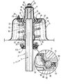
- the reference numeral 1 indicates overall a suspension for a motor vehicle wheel (not shown).
- the suspension 1 comprises essentially a shock absorber 2 provided with a casing 3 which is connected to an upright in a manner not shown, and a rod 4 which is connected, in the manner described hereinafter, to a portion 5 of the vehicle body by connection means formed in accordance with the present invention and indicated overall by 6.
- the connection means 6 consist essentially of a cup-shaped element 8, the end wall 9 of which is fixed to the end portion 10 of the rod 4 by a nut 11 and a washer 12.
- the cup-shaped element 8 has the inner surface of its end wall 9 resting on the top surface of the end portion 10, and also comprises a lateral wall 13 the inner surface of which faces the lateral surface of the end portion 10 of the rod 4.
- the lateral wall 13 of the element 8 comprises an edge 15 which is suitably shaped to define an annular projection extending radially outwards.
- connection neans 6 also comprise a sleeve 16 of elastomer material mounted coaxial to the shock absorber 2 so as to be essentially interposed between this latter and the body 5. More particularly, the sleeve 16 has a first portion 17 surrounding essentially the edge 15 of the cup-shaped element 8, and a second portion 18 mounted around the casing 3 of the shock absorber 2. The portion 18 has essentially an undulated inner surface and an undulated outer surface, and at the end distant fron the portion 17 comprises a hollow annular seat 19.
- the portion 17 of the sleeve 16 has an outer annular reinforcement 21 comprising essentially a profiled portion 22 surrounding the portion 17 of the sleeve 16 and a flat portion 23 which is connected to the body 5 by a plurality of bolts 24.
- the vehicle body portion 5 is essentially of dome configuration and in its upper zone comprises a through hole 26 from which there upwardly emerges a large part of the lateral wall 13 of the element 8 to which said rod 4 of the shock absorber 2 is connected.
- a ring 27 comprising in its downwardly facing part a seat 28 for housing the end of a spring 30, the opposite end of which rests on a disc 31 mounted coaxial to the casing 3 of the shock absorber 2.
- the disc 31 is connected to the casing 3 of the shock absorber 2 by a sleeve 32 fixed to the casing 3 and a bearing 33 interposed between the disc 31 and sleeve 32.
- the bearing 33 which is essentially of known type, comprises in particular a first and second race 35, 36 respectively fixed to the disc 31 and to the sleeve 32.
- the races 35, 36 are connected together by an annular peripheral gasket 38 to define an annular interspace 39 in which the balls 40 are located.
- the sleeve 32 supports the race 36 of the bearing 33 by neans of a radially extending annular portion 42.
- the sleeve 32 comprises an end portion 43 which is suitably bent outwards to engage the annular seat 19 of the sleeve 16 each time this latter moves axially downwards.
- the operation of the suspension 1 is of known type, and is therefore not described in detail. It should however be noted that the spring 30 nounted coaxial to the shock absorber 2 between the ring 27 and disc 31 improves the damping function of the entire suspension 1.
- connecting the rod 4 to the body 5 by means of the cup-shaped element 8 and sleeve 16 reduces the arm of application of the transverse forces transmitted to the rod 4 by the body 5. This therefore results in a reduction in the bending moment acting on the rod, and a reduction in the wear of the guides.
- the reduction in the load acting on the guide also results in a reduction in the shock absorber hysteresis, resulting in an overall improvement in driving comfort.
- the support for the disc 31 formed by the sleeve 32 and bearing 33 enables the spring 30 and casing 3 of the shock absorber 2 to rotate relative to each other, this rotation being necessary during steering as the spring 30 is rigid with the body 5.
Landscapes
- Engineering & Computer Science (AREA)
- Mechanical Engineering (AREA)
- Vehicle Body Suspensions (AREA)
Applications Claiming Priority (2)
| Application Number | Priority Date | Filing Date | Title |
|---|---|---|---|
| IT6809185 | 1985-12-20 | ||
| IT68091/85A IT1184037B (it) | 1985-12-20 | 1985-12-20 | Sospensione per una di un autoveicolo |
Publications (1)
| Publication Number | Publication Date |
|---|---|
| EP0226832A1 true EP0226832A1 (en) | 1987-07-01 |
Family
ID=11307777
Family Applications (1)
| Application Number | Title | Priority Date | Filing Date |
|---|---|---|---|
| EP86116202A Withdrawn EP0226832A1 (en) | 1985-12-20 | 1986-11-21 | Suspension for a motor vehicle wheel |
Country Status (3)
| Country | Link |
|---|---|
| EP (1) | EP0226832A1 (it) |
| BR (1) | BR8606495A (it) |
| IT (1) | IT1184037B (it) |
Cited By (5)
| Publication number | Priority date | Publication date | Assignee | Title |
|---|---|---|---|---|
| FR2630375A1 (fr) * | 1988-04-21 | 1989-10-27 | Skf France | Roulement de butee de suspension pour vehicule et son procede d'assemblage |
| EP0429405A1 (en) * | 1989-11-14 | 1991-05-29 | FIAT AUTO S.p.A. | A McPherson-type suspension unit for motor vehicles |
| US5170686A (en) * | 1990-07-24 | 1992-12-15 | Gildemeister Aktiengesllschaft | Turning machine |
| EP0602330A1 (de) * | 1992-12-18 | 1994-06-22 | Volkswagen Aktiengesellschaft | Axial auf Zug und/oder Druck belastbares Dämpferlager |
| FR2778606A1 (fr) * | 1998-05-14 | 1999-11-19 | Skf France | Dispositif de butee de suspension |
Families Citing this family (1)
| Publication number | Priority date | Publication date | Assignee | Title |
|---|---|---|---|---|
| FR3075105B1 (fr) * | 2017-12-20 | 2021-01-08 | Renault Sas | Coupelle d'amortisseur a zone d'encastrement partiellement decouplee |
Citations (5)
| Publication number | Priority date | Publication date | Assignee | Title |
|---|---|---|---|---|
| FR1220306A (fr) * | 1958-02-15 | 1960-05-24 | Daimler Benz Ag | Suspension de roue distincte pour véhicules, en particulier pour voitures automobiles |
| DE2249174A1 (de) * | 1972-10-06 | 1974-04-25 | Ford Werke Ag | Stossdaempfer, insbesondere fuer kraftfahrzeuge |
| FR2294869A1 (fr) * | 1974-12-20 | 1976-07-16 | Peugeot & Renault | Attache de liaison d'amortisseur de suspension de vehicule |
| FR2301399A1 (fr) * | 1975-02-19 | 1976-09-17 | Gen Motors Corp | Suspension de roue independante pour vehicule automobile |
| DE2626392A1 (de) * | 1975-02-19 | 1977-12-15 | Opel Adam Ag | Unabhaengige radaufhaengung fuer kraftfahrzeuge |
-
1985
- 1985-12-20 IT IT68091/85A patent/IT1184037B/it active
-
1986
- 1986-11-21 EP EP86116202A patent/EP0226832A1/en not_active Withdrawn
- 1986-12-17 BR BR8606495A patent/BR8606495A/pt not_active IP Right Cessation
Patent Citations (5)
| Publication number | Priority date | Publication date | Assignee | Title |
|---|---|---|---|---|
| FR1220306A (fr) * | 1958-02-15 | 1960-05-24 | Daimler Benz Ag | Suspension de roue distincte pour véhicules, en particulier pour voitures automobiles |
| DE2249174A1 (de) * | 1972-10-06 | 1974-04-25 | Ford Werke Ag | Stossdaempfer, insbesondere fuer kraftfahrzeuge |
| FR2294869A1 (fr) * | 1974-12-20 | 1976-07-16 | Peugeot & Renault | Attache de liaison d'amortisseur de suspension de vehicule |
| FR2301399A1 (fr) * | 1975-02-19 | 1976-09-17 | Gen Motors Corp | Suspension de roue independante pour vehicule automobile |
| DE2626392A1 (de) * | 1975-02-19 | 1977-12-15 | Opel Adam Ag | Unabhaengige radaufhaengung fuer kraftfahrzeuge |
Cited By (5)
| Publication number | Priority date | Publication date | Assignee | Title |
|---|---|---|---|---|
| FR2630375A1 (fr) * | 1988-04-21 | 1989-10-27 | Skf France | Roulement de butee de suspension pour vehicule et son procede d'assemblage |
| EP0429405A1 (en) * | 1989-11-14 | 1991-05-29 | FIAT AUTO S.p.A. | A McPherson-type suspension unit for motor vehicles |
| US5170686A (en) * | 1990-07-24 | 1992-12-15 | Gildemeister Aktiengesllschaft | Turning machine |
| EP0602330A1 (de) * | 1992-12-18 | 1994-06-22 | Volkswagen Aktiengesellschaft | Axial auf Zug und/oder Druck belastbares Dämpferlager |
| FR2778606A1 (fr) * | 1998-05-14 | 1999-11-19 | Skf France | Dispositif de butee de suspension |
Also Published As
| Publication number | Publication date |
|---|---|
| IT1184037B (it) | 1987-10-22 |
| BR8606495A (pt) | 1987-10-20 |
| IT8568091A0 (it) | 1985-12-20 |
Similar Documents
| Publication | Publication Date | Title |
|---|---|---|
| US4482135A (en) | MacPherson strut front suspension | |
| US5454585A (en) | Strut assembly with bearing axis alignment | |
| US4497523A (en) | Modular suspension strut bearing | |
| EP0253384B1 (en) | Double link type suspension system | |
| US4434977A (en) | Strut type suspension for a vehicle | |
| US4260177A (en) | Mounting arrangement for independent front wheel suspension of motor vehicles | |
| KR100476604B1 (ko) | 코일 스프링 및 지지 베어링을 구비한, 스프링 스트럿용장치 | |
| US8453774B2 (en) | In-wheel motor system for a steering wheel | |
| US5009401A (en) | Air spring suspension system with dual path isolation | |
| US4779855A (en) | Suspension support structure being free from torsion and pinch | |
| US4552467A (en) | Rolling bearings for strut-type suspensions | |
| US6398201B1 (en) | Vehicle shock absorber pad having a spring containment flange | |
| US4319768A (en) | Vehicle suspension strut | |
| EP0395214B1 (en) | End retainer for air spring in strut suspension | |
| EP0301517B1 (en) | Vehicle suspension mechanism | |
| US4486028A (en) | Upper support structure for front wheel suspension of automobile | |
| EP0312998A1 (en) | Double link type suspension system | |
| JP2004245413A (ja) | サスペンションスラスト軸受装置 | |
| CN102529627A (zh) | 带偏心转向轴线的支柱顶部安装件 | |
| US4883288A (en) | Suspension strut with side load support | |
| GB2158549A (en) | Suspension strut mounting for motor vehicles | |
| US5664892A (en) | Spring leg mounting and spring cup receiver | |
| EP0429405B1 (en) | A McPherson-type suspension unit for motor vehicles | |
| EP0193035B1 (en) | Air suspension | |
| GB2347905A (en) | A suspension arrangement having a bearing race incorporated within a resilient support element |
Legal Events
| Date | Code | Title | Description |
|---|---|---|---|
| PUAI | Public reference made under article 153(3) epc to a published international application that has entered the european phase |
Free format text: ORIGINAL CODE: 0009012 |
|
| AK | Designated contracting states |
Kind code of ref document: A1 Designated state(s): DE ES FR GB SE |
|
| 17P | Request for examination filed |
Effective date: 19870922 |
|
| 17Q | First examination report despatched |
Effective date: 19890331 |
|
| STAA | Information on the status of an ep patent application or granted ep patent |
Free format text: STATUS: THE APPLICATION IS DEEMED TO BE WITHDRAWN |
|
| 18D | Application deemed to be withdrawn |
Effective date: 19900712 |
|
| RIN1 | Information on inventor provided before grant (corrected) |
Inventor name: LEONARDIS, RAFFAELE |