EP0226875A1 - Soupape du genre anneau plat pour compresseur à piston - Google Patents
Soupape du genre anneau plat pour compresseur à piston Download PDFInfo
- Publication number
- EP0226875A1 EP0226875A1 EP86116594A EP86116594A EP0226875A1 EP 0226875 A1 EP0226875 A1 EP 0226875A1 EP 86116594 A EP86116594 A EP 86116594A EP 86116594 A EP86116594 A EP 86116594A EP 0226875 A1 EP0226875 A1 EP 0226875A1
- Authority
- EP
- European Patent Office
- Prior art keywords
- catcher
- valve
- openings
- valve plate
- plate
- Prior art date
- Legal status (The legal status is an assumption and is not a legal conclusion. Google has not performed a legal analysis and makes no representation as to the accuracy of the status listed.)
- Withdrawn
Links
Images



Classifications
-
- F—MECHANICAL ENGINEERING; LIGHTING; HEATING; WEAPONS; BLASTING
- F16—ENGINEERING ELEMENTS AND UNITS; GENERAL MEASURES FOR PRODUCING AND MAINTAINING EFFECTIVE FUNCTIONING OF MACHINES OR INSTALLATIONS; THERMAL INSULATION IN GENERAL
- F16K—VALVES; TAPS; COCKS; ACTUATING-FLOATS; DEVICES FOR VENTING OR AERATING
- F16K15/00—Check valves
- F16K15/14—Check valves with flexible valve members
- F16K15/16—Check valves with flexible valve members with tongue-shaped laminae
-
- F—MECHANICAL ENGINEERING; LIGHTING; HEATING; WEAPONS; BLASTING
- F16—ENGINEERING ELEMENTS AND UNITS; GENERAL MEASURES FOR PRODUCING AND MAINTAINING EFFECTIVE FUNCTIONING OF MACHINES OR INSTALLATIONS; THERMAL INSULATION IN GENERAL
- F16K—VALVES; TAPS; COCKS; ACTUATING-FLOATS; DEVICES FOR VENTING OR AERATING
- F16K15/00—Check valves
- F16K15/14—Check valves with flexible valve members
- F16K15/1402—Check valves with flexible valve members having an integral flexible member cooperating with a plurality of seating surfaces
-
- F—MECHANICAL ENGINEERING; LIGHTING; HEATING; WEAPONS; BLASTING
- F04—POSITIVE - DISPLACEMENT MACHINES FOR LIQUIDS; PUMPS FOR LIQUIDS OR ELASTIC FLUIDS
- F04B—POSITIVE-DISPLACEMENT MACHINES FOR LIQUIDS; PUMPS
- F04B39/00—Component parts, details, or accessories, of pumps or pumping systems specially adapted for elastic fluids, not otherwise provided for in, or of interest apart from, groups F04B25/00 - F04B37/00
- F04B39/10—Adaptations or arrangements of distribution members
- F04B39/1053—Adaptations or arrangements of distribution members the members being Hoerbigen valves
-
- Y—GENERAL TAGGING OF NEW TECHNOLOGICAL DEVELOPMENTS; GENERAL TAGGING OF CROSS-SECTIONAL TECHNOLOGIES SPANNING OVER SEVERAL SECTIONS OF THE IPC; TECHNICAL SUBJECTS COVERED BY FORMER USPC CROSS-REFERENCE ART COLLECTIONS [XRACs] AND DIGESTS
- Y10—TECHNICAL SUBJECTS COVERED BY FORMER USPC
- Y10T—TECHNICAL SUBJECTS COVERED BY FORMER US CLASSIFICATION
- Y10T137/00—Fluid handling
- Y10T137/7722—Line condition change responsive valves
- Y10T137/7837—Direct response valves [i.e., check valve type]
- Y10T137/7859—Single head, plural ports in parallel
- Y10T137/7861—Annular head
- Y10T137/7862—Central post on seat
- Y10T137/7863—Stop
- Y10T137/7864—With guide
Definitions
- the invention relates to a valve of the ring plate type for a piston compressor, with a valve seat fastened in the housing of the compressor, a catch attached to it at a distance and a movable valve plate between the valve seat and the catcher, which forms a flat surface at least on its side facing the catcher , wherein the valve seat and the valve plate have mutually offset openings for the gas flowing through and wherein in the catcher to the openings in the valve plate are aligned openings for the gas flowing through and the catcher forms a flat surface on the side facing the valve plate.
- the openings in the catcher can be provided to a certain extent on their inlet side with boundary surfaces parallel to the valve axis, which then expand conically towards the outlet side of the catcher plate. There is an edge at the transition from the axially parallel to the widening course of the boundary surfaces.
- the openings in the valve plate are limited by surfaces running parallel to the valve axis.
- the flow cross sections of the breakthroughs in the valve plate are the same as the cross section the breakthroughs in the catcher on its entry side.
- the invention has for its object to improve the valve of the type mentioned so that the flow losses of the valve are reduced in a structurally simple manner.
- the flow cross section of the openings in the valve plate is therefore larger than the narrowest cross section of the venturi-like openings in the catcher.
- the length of the venturi-like openings in the catcher is greater than that of the openings in the known catcher.
- the diffuser works more effectively, ie it has more kinetic energy converted into pressure energy, which is particularly due to the larger diffuser length.
- the range in which the ratio of the narrowest flow cross-section in the breakthrough of the catcher to the flow cross-section in the flush breakthrough of the valve plate can vary from 0.6 to 0.8.
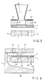
- a suction valve 2 is arranged in a housing 1 of a compressor cylinder (not shown in detail), which essentially consists of a plate-shaped valve seat 3, a valve plate 4, a steaming plate 5 and a plate-shaped catcher 6.
- the valve seat 3 rests with its edge on a shoulder 7 of a bore 8 in the housing 1 and is fastened in this bore by means of a lantern 9 which is pressed onto the edge of the valve seat 3 by an intake duct 10.
- the catcher 6 is fastened to the valve seat by means of a central screw 11 with nut l2, there being a distance between the two parts 3 and 6 for receiving the movable valve plate 4 and the steamer plate 5.
- a pin 23 is in an axial blind bore in the valve seat 3 and in the catcher 6 and extends through a correspondingly arranged bore in the valve plate 4 and the damper plate 5. It prevents the four plate-shaped parts from rotating relative to one another.
- openings 4 are provided in valve seat 3 on four different radii, which extend in the circumferential direction and their course at several points is interrupted by radial webs, which thus connect the ribs located between the openings.
- openings l4 Between two adjacent openings l3 there are 4 openings l4 in the valve plate which run parallel to the openings l3.
- the areas delimiting the openings l4 and l4 ' run parallel to the valve axis.
- openings l4 and l4 '5 openings l5 and l5' are provided in the steamer plate, which are of the same size and shape as the openings l4 and l4 '.
- the catcher 6 is aligned with the openings l4, l4 'and l5 and l5' openings l6, the boundary surfaces of which initially run somewhat parallel to the valve axis and subsequently widen in a straight, conical manner. In the area of the boundary surfaces of the openings l6 running parallel to the valve axis, these have a flow cross section of the same size as the openings l4 and l5 aligned with them.
- the breakthroughs l3, l4, l4 ', l5, l5' and l6 serve to pass the gas flowing in via the intake duct l0, which after leaving the breakthroughs l6 is in a space l8 located below the catcher 6 and delimited by the housing l, the so-called Nest collects, which is connected via a central channel 19 to the cylinder space 20 of the compressor (not shown).
- the catcher 6 in addition to the openings 16, the catcher 6 also has bores 2l, in each of which a helical spring 22 is accommodated; the springs extend through the damper plate 5 and bear against the valve plate 4.
- the springs 22 thus support the closing movement of the valve plate 4 during the compression stroke and when the compressed gas is pushed out.
- the gas flow forces move the valve plate 4 against the force of the springs 22 in the direction of the steam plate 5 and it, as mentioned, allows the gas to flow through the openings in the four plate-shaped parts, being on the way from the openings l3 to the openings l4, l4 'twice sharply by 90 ° is redirected. Another, but less sharp redirection takes place at the transition to room 18.
- the structure of the suction valve described so far is basically the same for a pressure valve, i.e. that it is installed in the housing l with the flow of the same valve components (valve seat, valve plate, steamer plate and catcher) in such a way that it opens during the compression stroke because of the flow direction reversed to the suction stroke.
- the valve seat clamped between the shoulder 7 and the lantern 9 is then adjacent to the space 18 and the catcher 6 projects into the lantern space, the lantern extending into the pressure channel.
- the valves shown in FIGS. 2 to 5 are pressure valves.
- the openings 66 in the catcher 60 are designed in the manner of a venturi nozzle in that the boundary surfaces of these openings are rounded from the inlet cross section of the catcher to the narrowest cross section of the opening in question and then from the narrowest cross section without a step into the subsequent diffuser-like extension pass over.
- the openings l5 and l4 in alignment with them in the damper plate 5 or valve plate 4 have a larger cross section.
- the transition of the catcher 60 also has a rounded course on its outer circumference, so that here, too, a venturi nozzle-like flow cross section results between the outer circumferential surface 25 and the adjacent boundary surface 9 'of the lantern 9. It is important here that the outer diameter of the valve plate 4 and the damper plate 5 is smaller than the largest diameter of the catcher 60.
- This shape of the catcher 60 and appropriate dimensioning of the diffusers (length, angle) in the openings 66 and also between the surfaces 25, 9 'and the dimensioning of the openings l4, l5 significantly reduce the losses which occur when the gas flows through, compared to the known design of the openings l4, l5, l6, since the gas flow coming from the openings l3 and passing through the openings l4, l5 into the openings 66, after passing through the narrowest cross section, contacts the widening boundary surfaces of the openings 66. The same applies to the gas flow passing the annular gap between the boundary surfaces 25 and 9 '.
- the kinetic energy of the gas is increasingly converted into pressure energy in the channels shaped like a Venturi nozzle, as a result of which the valve losses are reduced overall.
- valve seat 3, the valve plate 4, the steamer plate 5 and the catcher 60 are designed in the same way as the exemplary embodiment according to FIG. 2 with regard to the openings l3, l4, l5 and 66.
- a flow guide body 24 is provided on the valve seat 3 , which, starting from its base bearing against the valve seat, tapers towards opening 66.
- the tapering boundary surfaces of the flow guide body 24 are concave and meet at an acute angle, the apex of which lies on the axis of the opening 66. In the circumferential direction, the guide body 24 extends essentially over the same length as the associated opening 66.
- a flow guide body 28 is attached to the valve plate 4, aligned with the opening I3 in the valve seat 3, and its shape corresponds to that of the guide body 24 , but describes a full circle.
- the flow guide bodies 24 and 28 further support the endeavor to reduce the valve losses.
- a certain length of the venturi-like openings 66 is expedient, which has the consequence in the previously described exemplary embodiments of the invention that the thickness of the plate-shaped catcher 60 is greater than in the known valve according to Fig. l.
- the larger thickness of the catcher could be felt to be disadvantageous due to the higher weight.
- the venturi-like opening 66 in the valve according to FIG. 4 is realized in that a sheet metal body 60 'is inserted into the opening 3l, which is fastened with its inlet end near the damper plate 5 in the opening 3l is, e.g. by welding.
- FIG. 5 A similar embodiment is shown in Fig. 5, in which the venturi-like sheet metal body 60 'is not in the opening 3l itself, but is attached to the side of the plate-shaped part of the catcher 60 facing away from the steam plate 5.
- This attachment can be done, for example, by means of screws, not shown, which press the sheet metal body 60 'onto the plate-shaped part of the catcher via sheet metal strips 32.
- two adjacent molded bodies can be held with a sheet metal strip 32.
- valves described are used as a suction valve in the compressor, so that the gas emerging from the venturi-like openings 66 in the room 18 is subjected to a deflection, further improvements are possible on the valves, which contribute to reducing the valve losses.
- the openings 66 in the catcher 60 are again shaped like venturi nozzles, but the axis of the openings is skewed in such a way that the outlet cross section of these openings is closer to the valve axis than the associated inlet cross section.
- This has the advantage that the gas emerging from the openings 66 already receives a movement component in the direction of the central channel 19, which is also in the sense of reducing the flow losses due to deflection.
- the shape of the annular gap between the peripheral surface 25 of the catcher 60 and the boundary surface l 'of the housing l is venturi-like. Then the boundary surface l 'is designed such that the flow cross section increases continuously up to the adjacent opening 66.
- the outlet cross sections of the openings 66 in the catcher 60 are expanded towards the valve axis in such a way that the outlet cross sections of two adjacent openings almost merge into one another.
- the gas emerging from the openings 66 thereby flows almost parallel to the area l delimiting the space 18 'Of the housing l.
- the flow cross sections are dimensioned in such a way that the effective cross sections increase slightly in the direction of flow.
- the shape of the openings 66 is very similar to that according to FIG. 7, however, the openings are not incorporated directly into the plate-shaped catcher 60, but rather are formed by sheet metal bodies 60 ′′ which are fastened in a suitable manner to the plate-shaped part of the catcher are, for example by soldering or welding.
- the outermost sheet metal body its outer contour forms the boundary surface 25 of the annular gap, which here too - as in FIGS. 6 and 7 - together with the adjacent section of the boundary surface l 'has the shape of a venturi-like flow channel.
- the shaped body 60 'and 60 can also consist of plastic or ceramic instead of sheet metal.
Landscapes
- Engineering & Computer Science (AREA)
- General Engineering & Computer Science (AREA)
- Mechanical Engineering (AREA)
- Compressor (AREA)
- Multiple-Way Valves (AREA)
Applications Claiming Priority (2)
| Application Number | Priority Date | Filing Date | Title |
|---|---|---|---|
| CH5247/85 | 1985-12-09 | ||
| CH5247/85A CH668624A5 (de) | 1985-12-09 | 1985-12-09 | Ventil der ringplattenbauart fuer einen kolbenkompressor. |
Publications (1)
| Publication Number | Publication Date |
|---|---|
| EP0226875A1 true EP0226875A1 (fr) | 1987-07-01 |
Family
ID=4290400
Family Applications (1)
| Application Number | Title | Priority Date | Filing Date |
|---|---|---|---|
| EP86116594A Withdrawn EP0226875A1 (fr) | 1985-12-09 | 1986-11-28 | Soupape du genre anneau plat pour compresseur à piston |
Country Status (8)
| Country | Link |
|---|---|
| US (1) | US4703772A (fr) |
| EP (1) | EP0226875A1 (fr) |
| JP (1) | JPH0726692B2 (fr) |
| AU (1) | AU589717B2 (fr) |
| BR (1) | BR8606035A (fr) |
| CH (1) | CH668624A5 (fr) |
| MX (1) | MX159868A (fr) |
| ZA (1) | ZA869228B (fr) |
Cited By (1)
| Publication number | Priority date | Publication date | Assignee | Title |
|---|---|---|---|---|
| EP0319619A1 (fr) * | 1987-12-09 | 1989-06-14 | Ingersoll-Rand Company | Clapet de type plan pour fluides |
Families Citing this family (7)
| Publication number | Priority date | Publication date | Assignee | Title |
|---|---|---|---|---|
| JPH077542A (ja) * | 1993-04-28 | 1995-01-10 | Nec Corp | パッケージ障害表示システム |
| RU2290558C1 (ru) * | 2005-04-18 | 2006-12-27 | Государственное Образовательное Учреждение Высшего Профессионального Образования "Омский Государственный Технический Университет" | Клапан |
| US20130121860A1 (en) * | 2011-11-10 | 2013-05-16 | Gene Bluhm | Retrofit of a reciprocating compressor with a concentric valve |
| ITFI20110268A1 (it) * | 2011-12-12 | 2013-06-13 | Nuovo Pignone Spa | "automatic valve with interchangeable seat plate" |
| JP7362637B2 (ja) * | 2018-03-08 | 2023-10-17 | ブルクハルト コンプレッション アーゲー | 板弁およびその作動方法 |
| IT201900004978A1 (it) * | 2019-04-03 | 2020-10-03 | Nuovo Pignone Tecnologie Srl | Una valvola completamente attuata per una macchina alternativa e macchina alternativa comprendente detta valvola |
| EP4227531A1 (fr) | 2022-02-10 | 2023-08-16 | Burckhardt Compression AG | Soupape pour un compresseur à piston et procédé de fonctionnement d'une telle soupape |
Citations (9)
| Publication number | Priority date | Publication date | Assignee | Title |
|---|---|---|---|---|
| US2162832A (en) * | 1937-05-20 | 1939-06-20 | Nordberg Manufacturing Co | Valve |
| DE692177C (de) * | 1936-08-27 | 1940-06-17 | Hoerbiger & Co | Ringventil |
| FR959994A (fr) * | 1950-04-07 | |||
| FR1061785A (fr) * | 1952-03-13 | 1954-04-15 | D Applic Mecaniques Soc Ind | Perfectionnements aux obturateurs ou soupapes automatiques pour compresseurs et machines analogues |
| FR1063206A (fr) * | 1952-06-23 | 1954-04-30 | Anciens Ets Brissonneau & Lotz | Dispositif de distribution perfectionné pour compresseur volumétrique et compresseur en comportant application |
| US3158175A (en) * | 1963-02-08 | 1964-11-24 | Jaklitsch Franz | Compressor valves |
| FR1467898A (fr) * | 1965-12-21 | 1967-02-03 | Procedes Chabay | Perfectionnements aux boîtes à clapets pour compresseurs et appareils analogues |
| GB2040022A (en) * | 1979-01-26 | 1980-08-20 | Alsthom Atlantique | Non-return valve |
| EP0089773A1 (fr) * | 1982-03-18 | 1983-09-28 | Iic Mechanical Products Limited | Soupape de compresseur |
Family Cites Families (5)
| Publication number | Priority date | Publication date | Assignee | Title |
|---|---|---|---|---|
| US1695069A (en) * | 1925-10-14 | 1928-12-11 | Ingersoll Rand Co | Plate valve |
| US2186489A (en) * | 1936-08-26 | 1940-01-09 | Firm Hoerbiger & Co | Automatic annular valve |
| AT237179B (de) * | 1962-12-12 | 1964-12-10 | Hoerbiger Ventilwerke Ag | Plattenventil mit Lenkerführung |
| AT288582B (de) * | 1970-02-18 | 1971-03-10 | Hoerbiger Ventilwerke Ag | Plattenventil für Kolbenverdichter |
| JPS5139197B2 (fr) * | 1972-04-24 | 1976-10-26 |
-
1985
- 1985-12-09 CH CH5247/85A patent/CH668624A5/de not_active IP Right Cessation
-
1986
- 1986-11-28 EP EP86116594A patent/EP0226875A1/fr not_active Withdrawn
- 1986-12-04 US US06/937,987 patent/US4703772A/en not_active Expired - Lifetime
- 1986-12-05 ZA ZA869228A patent/ZA869228B/xx unknown
- 1986-12-08 MX MX4568A patent/MX159868A/es unknown
- 1986-12-08 JP JP29065686A patent/JPH0726692B2/ja not_active Expired - Lifetime
- 1986-12-08 BR BR8606035A patent/BR8606035A/pt not_active IP Right Cessation
- 1986-12-08 AU AU66183/86A patent/AU589717B2/en not_active Ceased
Patent Citations (9)
| Publication number | Priority date | Publication date | Assignee | Title |
|---|---|---|---|---|
| FR959994A (fr) * | 1950-04-07 | |||
| DE692177C (de) * | 1936-08-27 | 1940-06-17 | Hoerbiger & Co | Ringventil |
| US2162832A (en) * | 1937-05-20 | 1939-06-20 | Nordberg Manufacturing Co | Valve |
| FR1061785A (fr) * | 1952-03-13 | 1954-04-15 | D Applic Mecaniques Soc Ind | Perfectionnements aux obturateurs ou soupapes automatiques pour compresseurs et machines analogues |
| FR1063206A (fr) * | 1952-06-23 | 1954-04-30 | Anciens Ets Brissonneau & Lotz | Dispositif de distribution perfectionné pour compresseur volumétrique et compresseur en comportant application |
| US3158175A (en) * | 1963-02-08 | 1964-11-24 | Jaklitsch Franz | Compressor valves |
| FR1467898A (fr) * | 1965-12-21 | 1967-02-03 | Procedes Chabay | Perfectionnements aux boîtes à clapets pour compresseurs et appareils analogues |
| GB2040022A (en) * | 1979-01-26 | 1980-08-20 | Alsthom Atlantique | Non-return valve |
| EP0089773A1 (fr) * | 1982-03-18 | 1983-09-28 | Iic Mechanical Products Limited | Soupape de compresseur |
Cited By (1)
| Publication number | Priority date | Publication date | Assignee | Title |
|---|---|---|---|---|
| EP0319619A1 (fr) * | 1987-12-09 | 1989-06-14 | Ingersoll-Rand Company | Clapet de type plan pour fluides |
Also Published As
| Publication number | Publication date |
|---|---|
| US4703772A (en) | 1987-11-03 |
| JPH0726692B2 (ja) | 1995-03-29 |
| MX159868A (es) | 1989-09-22 |
| JPS62137477A (ja) | 1987-06-20 |
| BR8606035A (pt) | 1987-09-15 |
| AU6618386A (en) | 1987-06-11 |
| ZA869228B (en) | 1987-08-26 |
| AU589717B2 (en) | 1989-10-19 |
| CH668624A5 (de) | 1989-01-13 |
Similar Documents
| Publication | Publication Date | Title |
|---|---|---|
| EP0826426B1 (fr) | Arroseur | |
| DE2513769C2 (de) | Saugspannvorrichtung | |
| DE102016116550B4 (de) | Drehschieberventil mit kompaktem Dichtelement | |
| WO2003074912A1 (fr) | Soupape de retenue et de surpression combinee | |
| WO2021013340A1 (fr) | Distributeur à tiroir rotatif conçu pour un circuit de refroidissement | |
| DE19727356B4 (de) | Spender für Medien | |
| DE19601554A1 (de) | Einrichtung für das Ansaugen von Luft sowie Verfahren zur Regelung einer Einrichtung für das Ansaugen von Luft | |
| CH668624A5 (de) | Ventil der ringplattenbauart fuer einen kolbenkompressor. | |
| EP0832382B1 (fr) | Bague d'etancheite pour milieu gazeux | |
| DE7838964U1 (de) | Ventil | |
| EP0572748A1 (fr) | Soupape annulaire pour compresseur à piston | |
| DE102018124654B4 (de) | Einrichtung zum Abscheiden von Partikeln aus einem Gasstrom, Partikelabscheider und Kurbelgehäuseentlüftungssystem | |
| EP0346285A1 (fr) | Dispositif de clapet | |
| DE102018124652B4 (de) | Einrichtung zum Abscheiden von Partikeln aus einem Gasstrom, Partikelabscheider und Kurbelgehäuseentlüftungssystem | |
| DE4428742A1 (de) | Luftleitvorrichtung zum Abschluß von Ventilatoröffnungen in Bussen, Krankenwagen und sonstigen Spezialfahrzeugen | |
| AT401549B (de) | Selbsttätiges ventil | |
| DE3410078A1 (de) | Deckenluftauslass fuer hohe raeume | |
| DE3542389C2 (fr) | ||
| CH640606A5 (en) | Piston compressor | |
| WO2023152324A1 (fr) | Soupape pour un compresseur à piston et procédé de fonctionnement d'une telle soupape | |
| EP1000665A2 (fr) | Buse rotative | |
| DE2253542A1 (de) | Verfahren und anordnung zum erniedrigen des dynamischen druckes der verbrennungsluft an einem in den brennerkopf von oelfeuerungsaggregaten fuehrenden turbulator | |
| DE3310996C2 (fr) | ||
| DE3906210C2 (fr) | ||
| DE10139302C1 (de) | Luftansaugkanalsystem für Brennkraftmaschinen |
Legal Events
| Date | Code | Title | Description |
|---|---|---|---|
| PUAI | Public reference made under article 153(3) epc to a published international application that has entered the european phase |
Free format text: ORIGINAL CODE: 0009012 |
|
| AK | Designated contracting states |
Kind code of ref document: A1 Designated state(s): AT DE ES FR GB IT NL SE |
|
| 17P | Request for examination filed |
Effective date: 19871222 |
|
| 17Q | First examination report despatched |
Effective date: 19880909 |
|
| STAA | Information on the status of an ep patent application or granted ep patent |
Free format text: STATUS: THE APPLICATION HAS BEEN WITHDRAWN |
|
| 18W | Application withdrawn |
Withdrawal date: 19890218 |
|
| RIN1 | Information on inventor provided before grant (corrected) |
Inventor name: OSTERMANN, ERWIN |