EP0226925A2 - Dispositif pour couper des portions - Google Patents
Dispositif pour couper des portions Download PDFInfo
- Publication number
- EP0226925A2 EP0226925A2 EP86117031A EP86117031A EP0226925A2 EP 0226925 A2 EP0226925 A2 EP 0226925A2 EP 86117031 A EP86117031 A EP 86117031A EP 86117031 A EP86117031 A EP 86117031A EP 0226925 A2 EP0226925 A2 EP 0226925A2
- Authority
- EP
- European Patent Office
- Prior art keywords
- knife
- machine according
- nozzle
- plane
- working
- Prior art date
- Legal status (The legal status is an assumption and is not a legal conclusion. Google has not performed a legal analysis and makes no representation as to the accuracy of the status listed.)
- Granted
Links
Images


Classifications
-
- B—PERFORMING OPERATIONS; TRANSPORTING
- B26—HAND CUTTING TOOLS; CUTTING; SEVERING
- B26D—CUTTING; DETAILS COMMON TO MACHINES FOR PERFORATING, PUNCHING, CUTTING-OUT, STAMPING-OUT OR SEVERING
- B26D5/00—Arrangements for operating and controlling machines or devices for cutting, cutting-out, stamping-out, punching, perforating, or severing by means other than cutting
- B26D5/02—Means for moving the cutting member into its operative position for cutting
- B26D5/04—Means for moving the cutting member into its operative position for cutting by fluid pressure
Definitions
- the invention relates to a portioning machine with a filling pump and at least one outlet nozzle connected to it.
- portioning machines are mainly used in the food industry.
- a particular area of application is the meat processing industry, where the meat and possibly also bones and the like. is processed into a portionable mass by means of suitable comminution machines. If this mass leaves the outlet nozzle without a sausage casing, it must be stiff enough that it does not fall apart under its own weight. If this is guaranteed, a strand of mass is created, which can be divided into individual portions using this portioning machine.
- a very special area of application can be, for example, the production of so-called "cevapcici".
- the object is to design a portioning machine of the type described at the outset in such a way that the mass strand emerging from the nozzle mouth can be divided into sections of a predetermined length with the aid of this, without causing any significant deformation of the ends.
- the portioning machine should in particular be able to work continuously.
- the portioning machine is designed in accordance with the preamble of claim 1 in accordance with the characterizing part of this claim.
- the knife can be moved at predetermined, preferably adjustable, time intervals, in particular it can be moved.
- the knife in its infeed end position can be lifted off the nozzle mouth and can be reset against the nozzle mouth before the cutting movement begins.
- lifting the knife that can be moved along the nozzle mouth when cutting at the end of the cutting process one can work with a continuously escaping mass flow without having to put up with a deformation of the portion ends formed during cutting.
- this lifting of the knife from the nozzle mouth which can also give the separated portion an impulse in the direction of removal, requires timely approaching the nozzle mouth in order to be able to slide directly along the latter during the next working stroke.
- the knife is pivotally mounted on a sliding member about an axis running in its longitudinal direction and perpendicular to the infeed direction and is connected to a pivot drive. Due to this pivotable mounting of the knife, it can be fixed in place with respect to the nozzle and still achieve the necessary lifting and infeed movement.
- the pivot drive has a, in particular pneumatic, working cylinder, which at the same time forms a knife displacement drive, and that the working direction of the working piston runs approximately parallel to the working direction of the sliding member, the working piston having a swivel joint with a tab or the like.
- the knife or a knife holder is coupled.
- the axes of rotation of the swivel joint and the knife or a knife holder run parallel to one another.
- the rotary movement of the knife and its infeed movement do not necessarily have to take place separately, rather they can be at least partially superimposed.
- the shifting movement may only begin when the knife has reached the nozzle mouth or its intended shifting plane and has not yet reached the mass flow.
- a preferred embodiment of the invention is characterized in that the tab or the like is extended beyond the swivel joint of the working piston and the extension piece carries a stop element which is displaceably and rotatably mounted in an elongated hole of a control member, the elongated hole being parallel to Working cylinder and extends to the longitudinal axis of the sliding member.
- the knife can be swiveled away from the nozzle mouth in a simple manner, utilizing the displacement movement of the working piston.
- the working piston is displaced in the opposite direction, this causes a torque on the knife or a knife holder, which lifts the knife from the nozzle mouth, with a small pivoting movement about the pivot axis of the knife or his knife holder takes place on the sliding link.
- the cylinder of the working piston and the control member can be pivoted about parallel axes, which are also parallel to the pivot axis of the knife and the articulation axis of the Tab or the like run.
- the working cylinder and that In this way, control elements can oscillate around their suspension axes to the extent necessary.
- the knife is designed as a flat, in particular strip-like knife, the plane of which, when cutting, is inclined to the plane of the nozzle mouth or mouths. In this way, a particularly good, deformation-free or at least low-deformation cut is obtained.
- This knife can also be used to cut two or more strands running side by side at the same time.
- the geometric axis of the sliding member is expediently located approximately in the plane of the nozzle mouth or mouths. This means that the direction of displacement of the sliding member runs parallel to the plane of the nozzle mouth, while the plane of the knife includes a, preferably acute, angle with that of the nozzle mouth. This also contributes to the good work result and enables the mass to flow continuously even during the cutting process.
- a further embodiment of the invention is that an imaginary plane runs approximately perpendicular to the plane of the nozzle mouth through the geometric axes of the displacement member, the working piston and the control member. In this way, the knife can be moved back and forth on a circular path without tilting.
- the plane of the nozzle mouth is inclined to the longitudinal axis of the nozzle or nozzles.
- the inclination of the nozzle mouth is now chosen so that when cutting the plane of the knife, which, as I said, is also inclined to the geometric axis of the sliding member, is approximately perpendicular to the geometric axis of the outlet nozzle.
- the inclinations are chosen so that the knife moves when gliding along the oblique nozzle mouth both transversely to the mass strand and in its För derrichtun g .
- nozzle is located at the outlet of a metering device, in particular a gear metering pump.
- a gear metering pump This has a pair of gearwheels in a known manner and the mass to be conveyed is in the tooth gaps when the gearwheels are turned. The mass delivered per unit of time can be varied by changing the gear speed.
- a particularly preferred embodiment of the invention is characterized in that a plurality of gears are attached to a common drive shaft, the gear metering pump set having a plurality of gear pumps arranged next to one another is heard, the outlet nozzles being arranged in series next to each other at q are and a common knife is assigned to all.
- the length of this knife is determined by the number of nozzles and its width in the cutting direction is essentially determined by the thickness of the nozzle mouth.
- Characterized in that all driving gear wheels of the metering gear pumps arranged side by side sit on a common drive shaft and are thus driven by a common, in particular electrical, motor, with the same nozzle dimensioning, an equally strong mass strand emerges at the same speed from each nozzle. With each knife stroke, a portion number corresponding to the number of dosing pumps is created.
- a further embodiment of the invention is characterized in that the inlets of the gear metering pumps are connected to one another via a cross distributor, the inlet connection or the like of which is connected in terms of flow to the filling pump, so that the medium can be supplied to all the metering pumps via a single filling pump .
- Another preferred variant of the invention is by a transport that can be passed underneath the nozzle orifices link for the cut portions. It must be so arranged, in particular in terms of height, that on the one hand the portions are not deformed when placed on it, and on the other hand the escape of the mass flow and the cutting off by the transport member is not impaired.
- the transport member is designed in a particularly advantageous manner as a web that can be unwound from a roll, in particular made of paper. This paper web can then later be divided into transportable or dispatchable units with the portions lying thereon.
- the web of paper or the like is supported in a further embodiment of the invention on an endless conveyor belt, which is expediently adjustable in height, thereby adapting the height to the nozzle orifices and with an inclined course of the conveyor belt plane to the imaginary plane through the geometric axes of the sausage-shaped portions To allow variation of the portion length in a certain order.
- Another part of the invention results from the fact that the knife can be adjusted by means of a preferably adjustable clock device, in particular electropneumatically.
- the portion size corresponds to the set delivery rate of the filling pump between two pulses divided by the number of nozzles.
- the filling material to be divided into portions is introduced into the funnel 1 of the device 2.
- the device 2 contains at least one filling pump 3.
- at least one comminution device can also be installed in the device 2, which comminutes the material introduced into the hopper 1 to the desired degree of fineness, if necessary.
- the material conveyed by the filling pump 3 reaches a gear metering pump set 6.
- This is preceded by a transverse distributor 7, the connecting flange 8 of which is tightly connected to the connecting line 5.
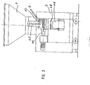
- Each gear metering pump of the metering pump set 6 has an outlet nozzle 9. In FIG. 2 nine such nozzles are shown. 3, the metering pump set consists of fourteen metering pumps 10.
- metering pumps 10 can vary within wide limits. The smallest unit has only a single metering pump, the inlet of which is then connected directly to the connecting line 5. Furthermore, it follows from Fig. 3 that 10 disk-like intermediate pieces 11 of different thickness can be used between the individual metering pumps. These not only set the side distance between the individual outlet nozzles 9, but can also serve as part of the pump housing.
- each nozzle mouth 12 is cut off or sheared off with the aid of a resettable and resettable knife 3 at the predetermined time, as a result of which the strand emerging from the nozzle, for example from stiff sausage or meat sausage meat, into individual more or less short or long Servings is divided.
- the knife thickness is comparatively small and its width is set according to the diameter of the nozzle mouth.
- the length of the knife depends on the width of the gear metering pump set 6 in the direction of the geometric axis 14 of the drive shaft 15 for, for example, all upper gear wheels 16 measured. In the latter case, the driving wheel is designated 16 and the driven wheel 17.
- the operation of such gear metering pumps is known and therefore does not need to be explained in more detail.
- the material is conveyed through the tooth gaps 18 and 19 to the outlet nozzle 9. Accordingly, all emerging mass strands are cut through with a single knife stroke.
- the knife 13 can be set in the direction of the arrow 20 and can be reset in the opposite direction. During cutting, it slides along the nozzle mouth 12, the strands being sheared off at high speed. This will be explained in more detail below.
- the knife 13 is pivotable about an axis 21 extending in its longitudinal direction and perpendicular to the feed direction 20 a sliding member 22 mounted and connected to a rotary drive 23.
- the exemplary embodiment also provides a knife holder 24, on which the knife, in particular replaceable, is held. Accordingly, in the exemplary embodiment, the knife is indirectly pivotably mounted on the slide member 22 via the knife holder 24.
- the swivel drive 23 has a, in particular pneumatic re, cylinder 25. This is advantageously a knife displacement drive at the same time.
- the working direction of the working piston 26 of this working cylinder 25 runs parallel to the working direction of the sliding member or its guide bearing 27.
- the working piston 26 is coupled via a swivel joint 28 with a tab 29 of the knife holder 24. This tab is extended beyond the swivel joint 28, the extension piece 30 carrying a stop element 31, for example bolt-shaped.
- the stop element 31 engages in an elongated hole 32 of a control member 33 and is displaceable therein in the direction of the double arrow 34 and rotatable about its axis.
- the elongated hole and in particular also the entire control member 33 extend parallel to the working cylinder 25 or displacement member 22, i.e. the geometrical axes of these three elements run parallel and preferably in a common plane. This is otherwise perpendicular to a plane through the knife 13 and all nozzle orifices.
- the axis 21 and the axis of the swivel joint 28 lie on a common imaginary axis that is laid to the geometric axes of the working cylinder and the displacement member Level, while due to the inclination of the tab 29 with its extension piece 30, the stop element 31 is removed from this imaginary plane and in the direction of the articulation axis 35 of the control member 33 on a beam 37.
- the working piston is also limited by an axis 36 Entirely pivoted.
- the lower end of the elongated hole 32 in the drawing forms a stop 38 for the stop element 31. It follows that the stop element 31 is at its greatest distance from the stop 38 in the starting position of the knife 13, that is to say in the retracted end position of the working piston 26. Starting from the upper end position shown in FIG. 4 in the direction of arrow 39, the knife 13 can be pivoted about the axis 23 towards the nozzle mouth 12. This is done automatically with the help of the rotary actuator 23 or more specifically the feed motion of the working piston 26. As soon as namely the working piston in the direction of the arrow 2 O is extended from its cylinder 40, acts on the knife holder 24 and hence to the knife 13 a torque in the direction of arrow 39.
- the working piston 26 of the swivel drive 23, which is also a knife drive, is extended further, this leads to the shearing off of the emerging strand and to the formation of a portion 43 or, in the case of several nozzles, to a corresponding number of portions.
- the stop element 31 lies against the stop 38.
- the extension piece 30 is pivoted clockwise around the stop element 31. This leads to the lifting of the knife 13 from the nozzle mouth 12. If the working piston 26 is now raised by reversing the, in particular pneumatic, double-acting working cylinder 25 against the arrow 20, i.e.
- the portion 43 or the portion group is placed on a transport member 45 that can be moved past beneath the nozzle orifices 12. This is preferably a web 47 that can be unwound from a roll 46, in particular a paper web.
- the portion of the transport member 45 to be covered with the portions 43 rests on the upper run of an endless conveyor belt 48.
- the height 49 of the conveyor belt 48 and in particular its upper run 50 can be set within predetermined limits. 1 that both the device 2 and the associated device 51 with the gear metering pump set 6 and the cutting device can be moved.
- a braking or locking device 52 ensures that the correct alignment with respect to the conveyor belt 48 is maintained.
- controller 53 By means of a controller 53, the conveying of the goods to be divided into portions and the feed movement of the cutting knife 13 are controlled so that the filling pump 3 can work continuously and the gearwheel -Dosing pump set 6 the correct amount is supplied, the cutting process should take place so that the resulting rear and front ends of the portions and the portions themselves are not deformed.
- the controller 53 also serves other purposes, for example, the correct operation of a Zerkleintiksein direction of the device 2.
- the portion size can be set on the controller 53. It is dependent on the flow rate, for example in the connecting line 5, and the time interval and between two working movements of the cutting knife 13.
Landscapes
- Physics & Mathematics (AREA)
- Fluid Mechanics (AREA)
- Life Sciences & Earth Sciences (AREA)
- Forests & Forestry (AREA)
- Engineering & Computer Science (AREA)
- Mechanical Engineering (AREA)
- Crushing And Pulverization Processes (AREA)
- Formation And Processing Of Food Products (AREA)
- Perforating, Stamping-Out Or Severing By Means Other Than Cutting (AREA)
Applications Claiming Priority (2)
| Application Number | Priority Date | Filing Date | Title |
|---|---|---|---|
| DE3545673 | 1985-12-21 | ||
| DE3545673A DE3545673C2 (de) | 1985-12-21 | 1985-12-21 | Portioniermaschine |
Publications (3)
| Publication Number | Publication Date |
|---|---|
| EP0226925A2 true EP0226925A2 (fr) | 1987-07-01 |
| EP0226925A3 EP0226925A3 (en) | 1989-03-22 |
| EP0226925B1 EP0226925B1 (fr) | 1990-11-22 |
Family
ID=6289311
Family Applications (1)
| Application Number | Title | Priority Date | Filing Date |
|---|---|---|---|
| EP86117031A Expired - Lifetime EP0226925B1 (fr) | 1985-12-21 | 1986-12-08 | Dispositif pour couper des portions |
Country Status (3)
| Country | Link |
|---|---|
| US (1) | US4747767A (fr) |
| EP (1) | EP0226925B1 (fr) |
| DE (1) | DE3545673C2 (fr) |
Cited By (4)
| Publication number | Priority date | Publication date | Assignee | Title |
|---|---|---|---|---|
| EP0473799B1 (fr) * | 1990-08-31 | 1993-08-04 | Frisco-Findus Ag | Découpage de la viande |
| GB2279236A (en) * | 1993-06-15 | 1995-01-04 | Pj Contracts Limited | Meat substitute manufacturing process and apparatus therefor |
| EP2781160A1 (fr) | 2013-03-21 | 2014-09-24 | Albert Handtmann Maschinenfabrik GmbH & Co. KG | Dispositif de fabrication de produits alimentaires coextrudés |
| EP3123867A1 (fr) * | 2015-07-30 | 2017-02-01 | Albert Handtmann Maschinenfabrik GmbH & Co. KG | Procede et dispositif d'orientation simplifiee d'une machine de remplissage pour la fabrication de saucisses |
Families Citing this family (12)
| Publication number | Priority date | Publication date | Assignee | Title |
|---|---|---|---|---|
| US5046940A (en) * | 1989-06-19 | 1991-09-10 | Automated Machinery Systems, Inc. | Apparatus for dividing and cutting dough |
| US5840345A (en) * | 1995-04-17 | 1998-11-24 | Ayash; Ajwad | Dough transport device |
| US5906297A (en) * | 1996-11-21 | 1999-05-25 | Cole; Russell H. | Multi-outlet depositor |
| EP1592497B1 (fr) * | 2003-01-20 | 2015-05-06 | DJM Foodprocessing B.V. | Diviseuse |
| HRP20041038A2 (en) * | 2004-11-04 | 2006-09-30 | Šturman Klaudio | Apparatus for serial production of minced-meat fingers |
| AT503323B1 (de) * | 2005-01-18 | 2008-11-15 | Erema | Strangformbauteil und verfahren zum anfahren desselben |
| ATE370662T1 (de) * | 2005-04-11 | 2007-09-15 | Handtmann Albert Maschf | Vorrichtung und verfahren zum geordneten ablegen von getrennten wurstportionen |
| DE102007050592A1 (de) * | 2007-10-23 | 2009-04-30 | Rieter Automatik Gmbh | Stranggießvorrichtung zur Erzeugung von Granulatkörnern aus Kunststoffmaterial und Verfahren zu deren Betrieb |
| US20130104710A1 (en) * | 2011-11-01 | 2013-05-02 | Hollymatic Corporation | Fluff pack portioning apparatus |
| EP3424329B1 (fr) * | 2017-07-06 | 2021-03-10 | Radie B.V. | Dispositif de fourniture d'un morceau de pâte sur un substrat mobile |
| CN112873319A (zh) * | 2021-01-20 | 2021-06-01 | 胡强 | 一种杜仲皮清理切割一体机 |
| CN114931659B (zh) * | 2022-04-21 | 2023-01-10 | 广州市爱家有方日用品有限公司 | 一种公共厕所长效除臭剂及其制备方法 |
Family Cites Families (11)
| Publication number | Priority date | Publication date | Assignee | Title |
|---|---|---|---|---|
| DE538189C (de) * | 1930-01-31 | 1931-11-11 | Thomas Asum | Presshefeteilapparat |
| US2090095A (en) * | 1936-09-22 | 1937-08-17 | George K Bainbridge | Candy cutting machine |
| GB712402A (en) * | 1951-04-24 | 1954-07-21 | S B Engineering Company Ltd | Improvements in or relating to the manufacture of plastic material such as ice cream |
| DE1695105U (de) * | 1953-04-07 | 1955-03-17 | Georg Bader | Einrichtung zur herstellung von raeucherwuersten ohne darm. |
| GB774347A (en) * | 1954-07-07 | 1957-05-08 | Swan Friteof Anderson | Block forming and wrapping machine |
| US2838012A (en) * | 1955-06-24 | 1958-06-10 | Edward Weidenmiller Co Inc | Cookie forming machine |
| US3019746A (en) * | 1957-09-10 | 1962-02-06 | Facs Mfg Company Inc | Extruding apparatus |
| US3415206A (en) * | 1965-03-31 | 1968-12-10 | Reisman Howard | Pretzel forming |
| US3776671A (en) * | 1970-11-13 | 1973-12-04 | Eskimo Pie Corp | Apparatus for producing confection bars |
| US3782876A (en) * | 1971-12-30 | 1974-01-01 | Reading Pretzel Machinery Co | Extrusion machine for pretzels and the like |
| US4392801A (en) * | 1979-06-13 | 1983-07-12 | Matthew Meyer | Apparatus for manufacturing cheese product |
-
1985
- 1985-12-21 DE DE3545673A patent/DE3545673C2/de not_active Expired - Fee Related
-
1986
- 1986-12-08 EP EP86117031A patent/EP0226925B1/fr not_active Expired - Lifetime
- 1986-12-19 US US06/944,666 patent/US4747767A/en not_active Expired - Fee Related
Cited By (8)
| Publication number | Priority date | Publication date | Assignee | Title |
|---|---|---|---|---|
| EP0473799B1 (fr) * | 1990-08-31 | 1993-08-04 | Frisco-Findus Ag | Découpage de la viande |
| GB2279236A (en) * | 1993-06-15 | 1995-01-04 | Pj Contracts Limited | Meat substitute manufacturing process and apparatus therefor |
| GB2279236B (en) * | 1993-06-15 | 1998-01-21 | Pj Contracts Limited | Meat substitute manufacturing process. |
| EP2781160A1 (fr) | 2013-03-21 | 2014-09-24 | Albert Handtmann Maschinenfabrik GmbH & Co. KG | Dispositif de fabrication de produits alimentaires coextrudés |
| CN104054791A (zh) * | 2013-03-21 | 2014-09-24 | 艾伯特.汉德特曼机器制造有限责任两合公司 | 用于制造共挤压食物产品的设备 |
| US9668492B2 (en) | 2013-03-21 | 2017-06-06 | Albert Handtmann Maschinenfabrik Gmbh & Co. Kg | Method for manufacturing coextruded food products |
| EP3123867A1 (fr) * | 2015-07-30 | 2017-02-01 | Albert Handtmann Maschinenfabrik GmbH & Co. KG | Procede et dispositif d'orientation simplifiee d'une machine de remplissage pour la fabrication de saucisses |
| US9723848B2 (en) | 2015-07-30 | 2017-08-08 | Albert Handtmann Maschinenfabrik Gmbh & Co. Kg | Method and device for simplified alignment of a filling machine for sausage production |
Also Published As
| Publication number | Publication date |
|---|---|
| EP0226925B1 (fr) | 1990-11-22 |
| DE3545673A1 (de) | 1987-06-25 |
| US4747767A (en) | 1988-05-31 |
| DE3545673C2 (de) | 1995-12-21 |
| EP0226925A3 (en) | 1989-03-22 |
Similar Documents
| Publication | Publication Date | Title |
|---|---|---|
| EP0226925B1 (fr) | Dispositif pour couper des portions | |
| EP0383246B1 (fr) | Procédé et appareil pour alimenter les flocons de fibres en quantité donnée | |
| DE3217643A1 (de) | Misch- und ablegevorrichtung fuer suess- und backwarenmassen | |
| EP1884489B1 (fr) | Dispositif et procédé destinés à la sortie dosée d'une marchandise pouvant s'écouler ou en vrac | |
| DE2139131A1 (de) | Verfahren zur dosierbaren Forderung von Materialien und Einrichtung zur Aus fuhrung des Verfahrens | |
| CH678915A5 (fr) | ||
| DE2147280C3 (de) | Vorrichtung zum Mischen von schüttbarem Erntegut | |
| DE3022631C1 (de) | Landwirtschaftliche Aufsammelpresse mit Einfuelloeffnung an der Unterseite des Presskanals | |
| DE3900414C2 (fr) | ||
| CH638378A5 (en) | Method and appliance for regulating the amount of brine injected in an injection-pickling machine | |
| DE3402567A1 (de) | Vorrichtung zum schneiden von stabmaterial, insbesondere von betonstahlstaeben | |
| DE3803677C2 (fr) | ||
| AT394959B (de) | Schneidanlage zum abschneiden von stuecken waehlbarer laenge von einem gitterrost | |
| EP0265783A2 (fr) | Dispositif d'alimentation pour broyeurs à cylindres, en particulier pour graines oléagineuses | |
| DE1951489A1 (de) | Vorrichtung zum Verteilen von insbesondere Butter auf einem Kuchenteig | |
| EP2298078A2 (fr) | Dispositif pour le pétrissage de portions de pâte | |
| DD284150B5 (de) | Vorrichtung zum auflockern von schuettgut | |
| DE2341337C2 (de) | Schneidvorrichtung zum selbsttätigen Portionieren von Hartkäse | |
| EP0578938B1 (fr) | Dispositif de coupe monté sur une extrudeuse pour la fabrication de blocs creux | |
| DE162024C (fr) | ||
| DE902164C (de) | Vorrichtung zur Herstellung von Wachskerzen | |
| DE625463C (de) | Giessmaschine zum Eingiessen von zaehfluessigen Zuckermassen in Schokoladenhohlkoerper | |
| DE925520C (de) | Vorrichtung zum Aufgeben plastischer, insbesondere keramischer Massen auf die Trockenanlage | |
| DE4230684C2 (de) | Vorrichtung zum Zerteilen einer Wurstkette | |
| DE3408859A1 (de) | Wurstfuellmaschine mit einer vorrichtung zur zipfelbildung und einer abschneideinrichtung fuer die wuerste |
Legal Events
| Date | Code | Title | Description |
|---|---|---|---|
| PUAI | Public reference made under article 153(3) epc to a published international application that has entered the european phase |
Free format text: ORIGINAL CODE: 0009012 |
|
| AK | Designated contracting states |
Kind code of ref document: A2 Designated state(s): FR GB |
|
| PUAL | Search report despatched |
Free format text: ORIGINAL CODE: 0009013 |
|
| AK | Designated contracting states |
Kind code of ref document: A3 Designated state(s): FR GB |
|
| 17P | Request for examination filed |
Effective date: 19890505 |
|
| 17Q | First examination report despatched |
Effective date: 19890913 |
|
| GRAA | (expected) grant |
Free format text: ORIGINAL CODE: 0009210 |
|
| AK | Designated contracting states |
Kind code of ref document: B1 Designated state(s): FR GB |
|
| ET | Fr: translation filed | ||
| GBT | Gb: translation of ep patent filed (gb section 77(6)(a)/1977) | ||
| PLBE | No opposition filed within time limit |
Free format text: ORIGINAL CODE: 0009261 |
|
| 26N | No opposition filed | ||
| PGFP | Annual fee paid to national office [announced via postgrant information from national office to epo] |
Ref country code: FR Payment date: 19941123 Year of fee payment: 9 |
|
| PGFP | Annual fee paid to national office [announced via postgrant information from national office to epo] |
Ref country code: GB Payment date: 19941128 Year of fee payment: 9 |
|
| PG25 | Lapsed in a contracting state [announced via postgrant information from national office to epo] |
Ref country code: GB Effective date: 19951208 |
|
| GBPC | Gb: european patent ceased through non-payment of renewal fee |
Effective date: 19951208 |
|
| PG25 | Lapsed in a contracting state [announced via postgrant information from national office to epo] |
Ref country code: FR Effective date: 19960830 |
|
| REG | Reference to a national code |
Ref country code: FR Ref legal event code: ST |