EP0226966A2 - Méthode et disposition pour la transmission d'informations entre des utilisateurs d'un système de bus - Google Patents
Méthode et disposition pour la transmission d'informations entre des utilisateurs d'un système de bus Download PDFInfo
- Publication number
- EP0226966A2 EP0226966A2 EP86117272A EP86117272A EP0226966A2 EP 0226966 A2 EP0226966 A2 EP 0226966A2 EP 86117272 A EP86117272 A EP 86117272A EP 86117272 A EP86117272 A EP 86117272A EP 0226966 A2 EP0226966 A2 EP 0226966A2
- Authority
- EP
- European Patent Office
- Prior art keywords
- bus
- participants
- instruction
- bit
- call command
- Prior art date
- Legal status (The legal status is an assumption and is not a legal conclusion. Google has not performed a legal analysis and makes no representation as to the accuracy of the status listed.)
- Granted
Links
Images

Classifications
-
- G—PHYSICS
- G06—COMPUTING OR CALCULATING; COUNTING
- G06F—ELECTRIC DIGITAL DATA PROCESSING
- G06F13/00—Interconnection of, or transfer of information or other signals between, memories, input/output devices or central processing units
- G06F13/38—Information transfer, e.g. on bus
- G06F13/382—Information transfer, e.g. on bus using universal interface adapter
- G06F13/385—Information transfer, e.g. on bus using universal interface adapter for adaptation of a particular data processing system to different peripheral devices
Definitions
- the invention relates to a method and an arrangement for the transmission of information between participants in a bus system.
- Such methods and arrangements are e.g. used for data transmission between device units (participants) that are connected to a bus system within a telecontrol station or another control station, that is, a station bus.
- Such a station bus is described, for example, in the essay "The Structure of Microcomputers and Their Use for Securing Telecontrol Telegrams", H. Herkert, NTG Technical Reports Volume 66, pages 47 to 55, Figure 1.
- the bus system shown is known in principle with the same structure both as an internal bus system in a microcomputer and as a station bus in a telecontrol station.
- Telecontrol stations can have several device units, which contain a microprocessor or a computer, as bus participants.
- Such a bus system contains as subsystems a data bus, a control bus and an address bus. Each of these subsystems has several parallel lines.
- additional lines can be provided between a central unit and the other bus subscribers for different purposes, for example as an interrupt line, for device addressing or for synchronization.
- the addresses used are designation codes for certain storage locations. The more memory locations the subscribers connected to the bus system have, the more address lines - typically 15 to 20 lines - are required; or multiplex systems with complex bus controls are necessary. For high-performance systems, very high clock rates have to be used, which means that the hardware complexity and sensitivity to interference are high.
- the invention has for its object to provide a method and an arrangement for transmitting data between participants in a bus system, which requires little effort for control and addressing and is still powerful.
- the transmission of instructions proposed by the invention which are elements of a higher system command language, has the advantage that, instead of a wide address bus (ie a bus with many lines), a narrow call command bus is sufficient (ie a bus with few lines) ) and depending on the meaning of the data to be transferred e.g. different protocols, procedures and security procedures can be agreed.
- Devices of different capabilities can be connected to the bus system, i.e. also devices that can only interpret a few codes or only one code.
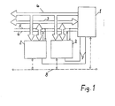
- Fig. 1 shows a schematic representation of the hardware arrangement in a telecontrol station.
- the station contains a central unit 1 and several peripheral devices 2 as participants in a bus system which contains a data bus 3 and a call-command bus 4.
- control lines 5, 6 and stub lines 7 are provided which connect the central unit 1 to the peripheral devices 2.
- a bit-serial bus 8 which is entered with a broken line and which connects all the devices 1, 2 to one another.
- the call command bus 4 which is provided instead of an address bus and whose function is explained in more detail below, all are other components of the telecontrol station known.
- Data is exchanged in the usual way between the subscribers 1, 2 via the 8-bit parallel, byte-serial data bus 3, for example.
- the data bus 3 can supplement the function of the 6-bit parallel call command bus 4, for example.
- control signals for carrying out a known handshake method for a synchronized data exchange are transmitted.
- the stub lines 7 are used for addressing the peripheral devices 2.
- the bit serial bus 8 is provided as a redundant bus.
- the central unit 1 contains a so-called bus manager for controlling the flow of information on all lines 3 to 8.
- the call-command bus 4 and the method according to the invention for data transmission between the subscribers 1, 2 on the transmission system 3 to 7, 8 are explained in more detail below and on the basis of the representation of functions in FIG. 2.
- the invention proposes to define a higher system command language, the elements of which are instructions called call command codes 9, which are transmitted on the call command bus 4 from the central unit 1 to the peripheral devices 2.
- call command codes 9 certain determinations are made, for example with regard to the transmission protocol, bus procedure 10 and security methods, which are to apply to a specific data transmission process.
- a call processing code 9 can be assigned a specific processing function in peripheral devices 2, which are triggered by the reception of the call command code 9.
- the central unit 1 selects a call command code 9 for initiating and carrying out data transmission or for triggering a specific reception-side activity, to which a specific procedure 10 for data exchange on the data bus 3 is assigned.
- the central unit 1 outputs the selected call command code 9 to the call command bus 4 and leaves the information coded with it pending on the call command bus 4 until the transmission process - which is being processed on the data bus 3 - is completed.
- at least one peripheral unit 2 is addressed via at least one of the spur lines 7.
- Several or all peripheral units 2 can also be addressed simultaneously. This results in a so-called device addressing, with which the selected periphery 2 is addressed as a whole, not a specific memory location within the peripheral unit 2.
- call command bus 4 If, for example, six lines are available for the call command bus 4, a maximum of 64 different call command codes 9 can be transmitted. Since a multitude of stipulations are made with a call command code 9, 64 call command codes 9, however, mean a significantly higher system capability and system flexibility than 64 simple memory location addresses.
- a suitable call command code 9 is selected according to the type and meaning of the data to be transmitted or the order to be transmitted.
- 9 different transmission protocols can be defined with call command codes. That is, e.g. be defined that data with variable or fixed block length are transmitted or as individual characters or variable data formats or data structures can be provided.
- the orders mentioned can e.g. Tax orders, such as Resetting or re-storing count values, test routines or switching off the peripheral unit 2.
- Other types of jobs are read jobs, e.g. "Send data input x", “send spontaneous data” or “send standard status” as well as write jobs such as "Write parameter type y" or "Write data output x".
- job command codes e.g. can be carried out with or without a check byte, with or without repetition and certain diagnostic routines can be selected.
- Peripheral units 2 connected to the bus system as participants can be of different types. For example, the further use of peripheral devices 2 from an older system is possible in the new system, such devices interpreting the call-command bus 4 as an address bus. Some call command codes 9 are reserved for these devices in order to display addresses. In addition, a specific handshake procedure can also be specified with a call command code 9 be placed, which can be taken into account, for example, particularly slow peripheral units 2 These measures make the bus system backwards compatible.
- peripheral units 2 which are specially designed for participation in the bus system according to the invention, by no means all devices need to understand all the call command codes 9.
- the peripheral units 2 are only equipped with the necessary skills in accordance with their task.
- the procedure 10 for the transmission of orders or data can also be selected depending on the meaning of the respective orders or data, specifically for a specific transmission process. Memory locations are addressed internally in the peripheral device and are - as a rule - not transmitted (logical addressing).
- the applicability of the invention is not limited to a bus arrangement according to FIG. 1, in which a bit-parallel call command bus 4 for transmitting the call command codes 9 and a bit-parallel data bus 3 are provided.
- the call command codes 9 and the procedures 10 defined therewith can also be used in a bit-serial bus system.
- the peripheral unit 2 is addressed with specially marked address characters in the transmitted bit sequence (telegram). However, the transmission process then takes place much slower, provided the clock rate is the same, and it is necessary to store the received call command code 9 in the peripheral unit 2. From this possibility e.g. Be used if a redundant bus system is to be provided, which is shown in Fig. 1 and 2 as a bit-serial bus system 8.
Landscapes
- Engineering & Computer Science (AREA)
- Theoretical Computer Science (AREA)
- Physics & Mathematics (AREA)
- General Engineering & Computer Science (AREA)
- General Physics & Mathematics (AREA)
- Small-Scale Networks (AREA)
- Information Transfer Systems (AREA)
Priority Applications (1)
| Application Number | Priority Date | Filing Date | Title |
|---|---|---|---|
| AT86117272T ATE104455T1 (de) | 1985-12-14 | 1986-12-11 | Verfahren und anordnung zur uebertragung von informationen zwischen teilnehmern an einem bussystem. |
Applications Claiming Priority (2)
| Application Number | Priority Date | Filing Date | Title |
|---|---|---|---|
| DE3544378 | 1985-12-14 | ||
| DE19853544378 DE3544378A1 (de) | 1985-12-14 | 1985-12-14 | Verfahren und anordnung zur uebertragung von informationen zwischen teilnehmern an einem bussystem |
Publications (3)
| Publication Number | Publication Date |
|---|---|
| EP0226966A2 true EP0226966A2 (fr) | 1987-07-01 |
| EP0226966A3 EP0226966A3 (en) | 1989-11-02 |
| EP0226966B1 EP0226966B1 (fr) | 1994-04-13 |
Family
ID=6288520
Family Applications (1)
| Application Number | Title | Priority Date | Filing Date |
|---|---|---|---|
| EP86117272A Expired - Lifetime EP0226966B1 (fr) | 1985-12-14 | 1986-12-11 | Méthode et disposition pour la transmission d'informations entre des utilisateurs d'un système de bus |
Country Status (3)
| Country | Link |
|---|---|
| EP (1) | EP0226966B1 (fr) |
| AT (1) | ATE104455T1 (fr) |
| DE (2) | DE3544378A1 (fr) |
Cited By (2)
| Publication number | Priority date | Publication date | Assignee | Title |
|---|---|---|---|---|
| US9689514B2 (en) | 2004-09-28 | 2017-06-27 | Advanced Composite Products & Technology, Inc. | Composite pipe to metal joint |
| US10342958B2 (en) | 2017-06-30 | 2019-07-09 | Abbott Cardiovascular Systems Inc. | System and method for correcting valve regurgitation |
Family Cites Families (4)
| Publication number | Priority date | Publication date | Assignee | Title |
|---|---|---|---|---|
| US3699525A (en) * | 1970-11-27 | 1972-10-17 | Honeywell Inf Systems | Use of control words to change configuration and operating mode of a data communication system |
| DE2800483B2 (de) * | 1978-01-05 | 1980-02-14 | Siemens Ag, 1000 Berlin Und 8000 Muenchen | Schaltungsanordnung zur Ansteuerung von Mikroprozessorperipherie |
| EP0109973A1 (fr) * | 1982-12-01 | 1984-06-13 | Johannes Reilhofer | Méthode et disposition pour la transmission de données entre différents calculateurs |
| WO1985003147A1 (fr) * | 1984-01-13 | 1985-07-18 | Term-Tronics Incorporated | Terminal de communication generique |
-
1985
- 1985-12-14 DE DE19853544378 patent/DE3544378A1/de not_active Withdrawn
-
1986
- 1986-12-11 AT AT86117272T patent/ATE104455T1/de not_active IP Right Cessation
- 1986-12-11 DE DE3689787T patent/DE3689787D1/de not_active Expired - Lifetime
- 1986-12-11 EP EP86117272A patent/EP0226966B1/fr not_active Expired - Lifetime
Cited By (6)
| Publication number | Priority date | Publication date | Assignee | Title |
|---|---|---|---|---|
| US9689514B2 (en) | 2004-09-28 | 2017-06-27 | Advanced Composite Products & Technology, Inc. | Composite pipe to metal joint |
| US9810353B2 (en) | 2004-09-28 | 2017-11-07 | Advanced Composite Products & Technology, Inc. | Method of making a composite tube to metal joint |
| US10378684B2 (en) | 2004-09-28 | 2019-08-13 | Advanced Composite Products & Technology, Inc. | Composite tube to metal joint apparatus |
| US11009156B2 (en) | 2004-09-28 | 2021-05-18 | Advanced Composite Products & Technology, Inc. | Composite drill pipe |
| US11143338B2 (en) | 2004-09-28 | 2021-10-12 | Advanced Composite Products & Technology, Inc. | Composite to metal end fitting joint |
| US10342958B2 (en) | 2017-06-30 | 2019-07-09 | Abbott Cardiovascular Systems Inc. | System and method for correcting valve regurgitation |
Also Published As
| Publication number | Publication date |
|---|---|
| DE3689787D1 (de) | 1994-05-19 |
| DE3544378A1 (de) | 1987-06-19 |
| EP0226966A3 (en) | 1989-11-02 |
| ATE104455T1 (de) | 1994-04-15 |
| EP0226966B1 (fr) | 1994-04-13 |
Similar Documents
| Publication | Publication Date | Title |
|---|---|---|
| EP0019757B1 (fr) | Dispositif de traitement de données comportant plusieurs préprocesseurs subordonnés à un processeur principal et disposés selon une structure d'arbre | |
| DE2953444C2 (de) | Anordnung und Verfahren für ein digitales Datenübertragungsnetzwerk | |
| DE2913288C2 (de) | Multiprozessoranlage mit einer Vielzahl von Prozessorbausteinen | |
| DE3787393T2 (de) | Verfahren zur Mehradresskommunikation. | |
| DE2350371C3 (de) | Verfahren und Einrichtung zur Prüfung und Wartung von Datenverarbeitungsanlagen mittels räumlich entfernter Wartungsstationen | |
| DE69326935T2 (de) | Verfahren und Vorrichtung zur Übertragung von einem Datenstrom mit hoher Bitfolgefrequenz über unabhängige digitale Kommunikationskanäle | |
| CH662025A5 (de) | Digitale vermittlungsanlage. | |
| EP0398876B1 (fr) | Procede pour identifier des peripheriques | |
| DE3826895C2 (fr) | ||
| EP0226966A2 (fr) | Méthode et disposition pour la transmission d'informations entre des utilisateurs d'un système de bus | |
| DE2812009C2 (de) | Nachrichtenübertragungssystem | |
| EP0105212B1 (fr) | Montage de circuit pour la transmission de signaux entre une ligne d'abonné et au moins une ligne de transmission d'un centre de télécommunications à services integrés | |
| DE2850252C2 (de) | Bildschirmtext-System | |
| CH656276A5 (de) | Verfahren und schaltungsanordnung zum uebertragen von datensignalen zwischen datenvermittlungseinrichtungen einer datenvermittlungsanlage. | |
| EP0060932B1 (fr) | Système avec deux micro-ordinateurs qui sont interconnectés par un coupleur de bus | |
| DE3003340A1 (de) | Verfahren und schaltungsanordnung zur uebertragung von binaeren signalen zwischen ueber ein zentrales busleitungssystem miteinander verbundenen anschlussgeraeten | |
| DE2914665B1 (de) | Fernmeldesystem,insbesondere Bildschirmtext-System,sowie teilzentraler und dezentraler Schaltungsbaustein fuer dieses System | |
| DE3603013C2 (fr) | ||
| EP0475180A1 (fr) | Procédé de transmission de paquets de communication entre des lignes de raccordement existantes dans un commutateur | |
| EP0348810B1 (fr) | Méthode pour l'adressage d'unités de processeur et circuit pour la mise en oeuvre de la méthode | |
| EP0477627B1 (fr) | Procédé pour connecter des terminaux de communication dans les réseaux de commutation à services integrés | |
| DE3136495C2 (fr) | ||
| DE3802099C1 (fr) | ||
| EP0460403B1 (fr) | Procédé pour la transmission de signaux de données dans des centraux de communication | |
| EP0385126A2 (fr) | Système de surveillance en service et/ou de commande de systèmes de transmission de la technique de transmission électrique d'informations |
Legal Events
| Date | Code | Title | Description |
|---|---|---|---|
| PUAI | Public reference made under article 153(3) epc to a published international application that has entered the european phase |
Free format text: ORIGINAL CODE: 0009012 |
|
| AK | Designated contracting states |
Kind code of ref document: A2 Designated state(s): AT CH DE LI NL SE |
|
| RAP1 | Party data changed (applicant data changed or rights of an application transferred) |
Owner name: ASEA BROWN BOVERI AKTIENGESELLSCHAFT |
|
| PUAL | Search report despatched |
Free format text: ORIGINAL CODE: 0009013 |
|
| AK | Designated contracting states |
Kind code of ref document: A3 Designated state(s): AT CH DE LI NL SE |
|
| 17P | Request for examination filed |
Effective date: 19900330 |
|
| 17Q | First examination report despatched |
Effective date: 19920827 |
|
| GRAA | (expected) grant |
Free format text: ORIGINAL CODE: 0009210 |
|
| AK | Designated contracting states |
Kind code of ref document: B1 Designated state(s): AT CH DE LI NL SE |
|
| REF | Corresponds to: |
Ref document number: 104455 Country of ref document: AT Date of ref document: 19940415 Kind code of ref document: T |
|
| REF | Corresponds to: |
Ref document number: 3689787 Country of ref document: DE Date of ref document: 19940519 |
|
| EAL | Se: european patent in force in sweden |
Ref document number: 86117272.4 |
|
| PLBE | No opposition filed within time limit |
Free format text: ORIGINAL CODE: 0009261 |
|
| STAA | Information on the status of an ep patent application or granted ep patent |
Free format text: STATUS: NO OPPOSITION FILED WITHIN TIME LIMIT |
|
| 26N | No opposition filed | ||
| PGFP | Annual fee paid to national office [announced via postgrant information from national office to epo] |
Ref country code: DE Payment date: 20051212 Year of fee payment: 20 |
|
| PGFP | Annual fee paid to national office [announced via postgrant information from national office to epo] |
Ref country code: SE Payment date: 20051214 Year of fee payment: 20 Ref country code: NL Payment date: 20051214 Year of fee payment: 20 |
|
| PGFP | Annual fee paid to national office [announced via postgrant information from national office to epo] |
Ref country code: CH Payment date: 20051215 Year of fee payment: 20 |
|
| PGFP | Annual fee paid to national office [announced via postgrant information from national office to epo] |
Ref country code: AT Payment date: 20051220 Year of fee payment: 20 |
|
| PG25 | Lapsed in a contracting state [announced via postgrant information from national office to epo] |
Ref country code: NL Free format text: LAPSE BECAUSE OF EXPIRATION OF PROTECTION Effective date: 20061211 |
|
| REG | Reference to a national code |
Ref country code: CH Ref legal event code: PL |
|
| NLV7 | Nl: ceased due to reaching the maximum lifetime of a patent |
Effective date: 20061211 |
|
| EUG | Se: european patent has lapsed |