EP0226986A2 - Chaîne de transport à douilles - Google Patents
Chaîne de transport à douilles Download PDFInfo
- Publication number
- EP0226986A2 EP0226986A2 EP86117387A EP86117387A EP0226986A2 EP 0226986 A2 EP0226986 A2 EP 0226986A2 EP 86117387 A EP86117387 A EP 86117387A EP 86117387 A EP86117387 A EP 86117387A EP 0226986 A2 EP0226986 A2 EP 0226986A2
- Authority
- EP
- European Patent Office
- Prior art keywords
- chain
- bush
- conveyor chain
- plates
- bush conveyor
- Prior art date
- Legal status (The legal status is an assumption and is not a legal conclusion. Google has not performed a legal analysis and makes no representation as to the accuracy of the status listed.)
- Withdrawn
Links
- 230000008719 thickening Effects 0.000 claims description 5
- 230000000694 effects Effects 0.000 abstract description 4
- 230000035939 shock Effects 0.000 abstract 1
- 238000004519 manufacturing process Methods 0.000 description 5
- 239000000463 material Substances 0.000 description 5
- 238000005242 forging Methods 0.000 description 3
- 229910000831 Steel Inorganic materials 0.000 description 2
- 230000005540 biological transmission Effects 0.000 description 2
- 230000002349 favourable effect Effects 0.000 description 2
- 230000002093 peripheral effect Effects 0.000 description 2
- 239000010959 steel Substances 0.000 description 2
- 206010040954 Skin wrinkling Diseases 0.000 description 1
- 238000005452 bending Methods 0.000 description 1
- 230000015572 biosynthetic process Effects 0.000 description 1
- 230000007774 longterm Effects 0.000 description 1
- 230000007704 transition Effects 0.000 description 1
- 230000037303 wrinkles Effects 0.000 description 1
Images

Classifications
-
- B—PERFORMING OPERATIONS; TRANSPORTING
- B65—CONVEYING; PACKING; STORING; HANDLING THIN OR FILAMENTARY MATERIAL
- B65G—TRANSPORT OR STORAGE DEVICES, e.g. CONVEYORS FOR LOADING OR TIPPING, SHOP CONVEYOR SYSTEMS OR PNEUMATIC TUBE CONVEYORS
- B65G17/00—Conveyors having an endless traction element, e.g. a chain, transmitting movement to a continuous or substantially-continuous load-carrying surface or to a series of individual load-carriers; Endless-chain conveyors in which the chains form the load-carrying surface
- B65G17/30—Details; Auxiliary devices
- B65G17/38—Chains or like traction elements; Connections between traction elements and load-carriers
-
- B—PERFORMING OPERATIONS; TRANSPORTING
- B65—CONVEYING; PACKING; STORING; HANDLING THIN OR FILAMENTARY MATERIAL
- B65G—TRANSPORT OR STORAGE DEVICES, e.g. CONVEYORS FOR LOADING OR TIPPING, SHOP CONVEYOR SYSTEMS OR PNEUMATIC TUBE CONVEYORS
- B65G17/00—Conveyors having an endless traction element, e.g. a chain, transmitting movement to a continuous or substantially-continuous load-carrying surface or to a series of individual load-carriers; Endless-chain conveyors in which the chains form the load-carrying surface
- B65G17/12—Conveyors having an endless traction element, e.g. a chain, transmitting movement to a continuous or substantially-continuous load-carrying surface or to a series of individual load-carriers; Endless-chain conveyors in which the chains form the load-carrying surface comprising a series of individual load-carriers fixed, or normally fixed, relative to traction element
- B65G17/126—Bucket elevators
-
- B—PERFORMING OPERATIONS; TRANSPORTING
- B65—CONVEYING; PACKING; STORING; HANDLING THIN OR FILAMENTARY MATERIAL
- B65G—TRANSPORT OR STORAGE DEVICES, e.g. CONVEYORS FOR LOADING OR TIPPING, SHOP CONVEYOR SYSTEMS OR PNEUMATIC TUBE CONVEYORS
- B65G2201/00—Indexing codes relating to handling devices, e.g. conveyors, characterised by the type of product or load being conveyed or handled
- B65G2201/02—Articles
-
- B—PERFORMING OPERATIONS; TRANSPORTING
- B65—CONVEYING; PACKING; STORING; HANDLING THIN OR FILAMENTARY MATERIAL
- B65G—TRANSPORT OR STORAGE DEVICES, e.g. CONVEYORS FOR LOADING OR TIPPING, SHOP CONVEYOR SYSTEMS OR PNEUMATIC TUBE CONVEYORS
- B65G2201/00—Indexing codes relating to handling devices, e.g. conveyors, characterised by the type of product or load being conveyed or handled
- B65G2201/04—Bulk
Definitions
- the invention relates to bush conveyor chains which are used as pulling elements for link belt conveyors and bucket elevators.
- the load on the chains results from the dead weight of the supporting elements, such as conveying troughs and buckets, the dead weight of the conveyor chains and the load share from the goods being conveyed.
- dynamic additional loads from the polygon effect are added to this, particularly in the case of bucket elevators with a high peripheral speed for centrifugal emptying.
- Increasing the load capacity of the chains usually also means increasing their own weight.
- the point is quickly reached where the possible increase in the payload is consumed by the higher weight of the chain.
- Measures to reduce the dynamic additional loads for example by using chains with a smaller pitch, are possible, but here there are economic limits.
- the weight of the support members can hardly be reduced for economic and technical reasons.
- the object of the invention is therefore to reduce the weight of the chains by means of appropriate manufacturing and material-related measures while at the same time improving the operational strength.
- bush conveyor chains are used as flat link chains and as fork link chains.
- Flat link chains have tabs made from flat steel.
- the outer plates are usually designed as angled plates.
- a disadvantage of the flat link chains is the limited operational stability due to high voltage peaks at the edge of the bore and the poor material utilization resulting from this.
- Fork link chains with cranked links are used as tension elements for crawler tracks and have openings between the link holes for attaching the base plates. Additional holes are provided for the fastening screws through the remaining web, starting from the openings.
- An advantage of the fork link chain is the possibility of economical production in large quantities on appropriately rationalized production lines, starting from a drop-forged blank.
- the object of the invention is to improve the operational strength of the flat link chain which is more favorable in terms of stress while at the same time reducing its own weight using the inexpensive production facilities available for forged link chains.
- the tabs of the bush conveyor chains are designed with relief cutouts between the bores, which results in an increase in operational strength while reducing its own weight. Since the flat plate does not have an offset, the risk of wrinkles is also eliminated. They are manufactured by hot forming, preferably by drop forging. The superior material properties of the forged steels in terms of strength and ductility in conjunction with a uniform structure also help to further improve the operational strength for an optimal ratio of payload to dead weight.
- burrs are formed as notches that can only be removed with great effort. These ridges do not apply if, according to a further claim of the invention, the relief cutout is not carried out continuously. What remains is a residual cross-section in a U or double-T shape, the additional weight of which is largely compensated for by smooth, low-notch transitions from the remaining web to the outer flap surfaces. The remaining web also means an increase in the load-bearing capacity due to shear forces, e.g. in bucket elevator operation with toothless drive wheels when the brackets are supported on corresponding support surfaces on the drive wheels.
- the thickening of the link plates on the sprocket run-up side has the purpose of also creating a large contact surface here for long idle times without local overload on the drive wheel.
- a further improvement results from a non-rigid connection between chain and support member.
- a mounting bracket is loosely attached, ie with play, while there is a fixed connection between the mounting brackets and the support members.
- this arrangement reduces the dynamic stresses on the buckets caused by the polygon effect to such an extent that they can be carried out much more easily.
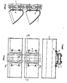
- Figure 1 shows an example of an embodiment of a bush conveyor chain according to the invention with forged flat plates.
- Inner plates (1) and outer plates (2) have relief cutouts (3) that are not continuous.
- the tab cross section is given a U-shape according to FIG. 3.
- the remaining web in the area of the relief cutout can also be arranged differently, so that e.g. a double-T-shaped tab cross-section is created.
- the bush conveyor chain is completed by the bushes (6) and the bolts (7).
- the bolts are extended on both sides outwards (8), in accordance with a further patent claim.
- FIGS. 1 and 2 show a particularly preferred embodiment of the invention.
- the bushing conveyor chain (9) in the exemplary embodiment according to FIGS. 1 and 2 is connected to the cups (11) via a screw connection (12) by means of angled support straps (10).
- angled support straps (10) Through play between the drive plates (10) and the extended chain bolts, the impacts from the chain dynamics are damped to such an extent that the cups (11) on the weld seams of the side plates and at the fastening points (12) are no longer endangered by crack formation and are even made lighter can.
Landscapes
- Engineering & Computer Science (AREA)
- Mechanical Engineering (AREA)
- Chain Conveyers (AREA)
Applications Claiming Priority (2)
| Application Number | Priority Date | Filing Date | Title |
|---|---|---|---|
| DE3545634 | 1985-12-21 | ||
| DE19853545634 DE3545634A1 (de) | 1985-12-21 | 1985-12-21 | Buchsenfoerderkette |
Publications (2)
| Publication Number | Publication Date |
|---|---|
| EP0226986A2 true EP0226986A2 (fr) | 1987-07-01 |
| EP0226986A3 EP0226986A3 (fr) | 1988-07-06 |
Family
ID=6289284
Family Applications (1)
| Application Number | Title | Priority Date | Filing Date |
|---|---|---|---|
| EP86117387A Withdrawn EP0226986A3 (fr) | 1985-12-21 | 1986-12-13 | Chaíne de transport à douilles |
Country Status (3)
| Country | Link |
|---|---|
| EP (1) | EP0226986A3 (fr) |
| JP (1) | JPS62175310A (fr) |
| DE (1) | DE3545634A1 (fr) |
Cited By (2)
| Publication number | Priority date | Publication date | Assignee | Title |
|---|---|---|---|---|
| DE102010054567A1 (de) * | 2010-12-15 | 2012-06-21 | Rheinmetall Landsysteme Gmbh | Plastisch verformbare Lagerung |
| CN104555263A (zh) * | 2014-12-31 | 2015-04-29 | 杭州和泰机电工业有限公司 | 一种熟料链斗式输送机上的单向制动模锻链 |
Families Citing this family (3)
| Publication number | Priority date | Publication date | Assignee | Title |
|---|---|---|---|---|
| DE4233552C2 (de) * | 1992-09-30 | 1995-08-03 | Rud Ketten Rieger & Dietz | Laschenkette und mit dieser ausgerüstetes Becherwerk |
| AT402283B (de) * | 1995-10-04 | 1997-03-25 | Dalferth Hans | Laschenkette |
| DE10130256A1 (de) * | 2001-06-22 | 2003-01-02 | Heko Ketten Gmbh | Becherwerk |
Family Cites Families (6)
| Publication number | Priority date | Publication date | Assignee | Title |
|---|---|---|---|---|
| DD11515A (fr) * | ||||
| DE406725C (de) * | 1921-12-06 | 1924-12-02 | Hans Renold Ltd | Gliederkette |
| US2182443A (en) * | 1937-12-07 | 1939-12-05 | Link Belt Co | Roller chain and link for conveyers |
| GB1180133A (en) * | 1967-08-07 | 1970-02-04 | Redler Conveyors Ltd | Improvements in or relating to Conveying Elements for Conveyors. |
| DE1805815A1 (de) * | 1968-10-29 | 1970-05-27 | Max Schulz | Kettenfoerderer |
| DE7034499U (de) * | 1970-09-17 | 1974-08-29 | Stiels H Konservenmaschinen | Foerderkette |
-
1985
- 1985-12-21 DE DE19853545634 patent/DE3545634A1/de not_active Withdrawn
-
1986
- 1986-12-13 EP EP86117387A patent/EP0226986A3/fr not_active Withdrawn
- 1986-12-22 JP JP30405686A patent/JPS62175310A/ja active Pending
Cited By (3)
| Publication number | Priority date | Publication date | Assignee | Title |
|---|---|---|---|---|
| DE102010054567A1 (de) * | 2010-12-15 | 2012-06-21 | Rheinmetall Landsysteme Gmbh | Plastisch verformbare Lagerung |
| DE102010054567B4 (de) * | 2010-12-15 | 2015-08-20 | Rheinmetall Landsysteme Gmbh | Plastisch verformbare Lagerung |
| CN104555263A (zh) * | 2014-12-31 | 2015-04-29 | 杭州和泰机电工业有限公司 | 一种熟料链斗式输送机上的单向制动模锻链 |
Also Published As
| Publication number | Publication date |
|---|---|
| DE3545634A1 (de) | 1987-06-25 |
| EP0226986A3 (fr) | 1988-07-06 |
| JPS62175310A (ja) | 1987-08-01 |
Similar Documents
| Publication | Publication Date | Title |
|---|---|---|
| DE112009005437B4 (de) | Tragstrukturkonstruktion für eine Personenbeförderungsvorrichtung | |
| EP0672013B1 (fr) | Dispositif d'entrainement et de guidage pour engins de manutention continue | |
| EP1236661A1 (fr) | Chaíne à rouleaux | |
| DE69301689T2 (de) | Fördereinrichtung mit variabler Geschwindigkeit für beschleunigte Personenfahrbänder | |
| DE102021109959A1 (de) | Horizontalboden aus einer Tragkonstruktion und darauf verlegten Bodenplatten | |
| US20060054458A1 (en) | Stepchain link for an escalator | |
| EP1819941B1 (fr) | Chaine articulee destinee notamment a une transmission de vehicule | |
| DE3545634A1 (de) | Buchsenfoerderkette | |
| WO2010045910A1 (fr) | Chaîne dentée, en particulier pour entraînement de véhicules | |
| DE102004013696B4 (de) | Schubkette zur Kraftübertragung von mindestens einem Kettenrad eines Getriebes | |
| DE8700047U1 (de) | Buchsenförderkette | |
| DE19844304C1 (de) | Kettenförderer für Transportgut | |
| EP1443012B1 (fr) | Escalier mécanique ou trottoir roulant | |
| DE102020104174B4 (de) | Kettenglied sowie Gliederkette mit derartigen Kettengliedern | |
| DE102021000170A1 (de) | Gutförderer | |
| DE905836C (de) | Gliederfoerderband | |
| DE20103711U1 (de) | Gelenk(förder)kette für einen Zellenförderer, insbesondere ein (Ketten-)Becherwerk mit Zentralkette(n) | |
| EP1963708A1 (fr) | Chaîne articulée | |
| DE629359C (de) | Bremsfoerderer mit in einer Lutte, die mit seitlichen Beladeoeffnungen versehen ist, umlaufendem Stauscheibenband | |
| DE1556173A1 (de) | Kettenfoerderer | |
| DE10227025C2 (de) | Becherwerk | |
| DE10335300A1 (de) | Stahlgelenkkette | |
| DE102004034589B3 (de) | Kettenzug | |
| DE19636044C2 (de) | Traverse für das Aufhängen von Lasten an Profilen in einer verwindungssteifen Ausführung für alle extremen Belastungsfälle | |
| DE2658823A1 (de) | Vorrichtung zum betrieb eines aufzuges |
Legal Events
| Date | Code | Title | Description |
|---|---|---|---|
| PUAI | Public reference made under article 153(3) epc to a published international application that has entered the european phase |
Free format text: ORIGINAL CODE: 0009012 |
|
| AK | Designated contracting states |
Kind code of ref document: A2 Designated state(s): BE DE ES FR GB IT |
|
| PUAL | Search report despatched |
Free format text: ORIGINAL CODE: 0009013 |
|
| AK | Designated contracting states |
Kind code of ref document: A3 Designated state(s): BE DE ES FR GB IT |
|
| STAA | Information on the status of an ep patent application or granted ep patent |
Free format text: STATUS: THE APPLICATION IS DEEMED TO BE WITHDRAWN |
|
| 18D | Application deemed to be withdrawn |
Effective date: 19890109 |
|
| RIN1 | Information on inventor provided before grant (corrected) |
Inventor name: RINIO, WOLFGANG |