EP0227041A2 - Appareil d'enregistrement d'images - Google Patents
Appareil d'enregistrement d'images Download PDFInfo
- Publication number
- EP0227041A2 EP0227041A2 EP86117633A EP86117633A EP0227041A2 EP 0227041 A2 EP0227041 A2 EP 0227041A2 EP 86117633 A EP86117633 A EP 86117633A EP 86117633 A EP86117633 A EP 86117633A EP 0227041 A2 EP0227041 A2 EP 0227041A2
- Authority
- EP
- European Patent Office
- Prior art keywords
- image
- photosensitive
- medium
- pressure
- sensitive
- Prior art date
- Legal status (The legal status is an assumption and is not a legal conclusion. Google has not performed a legal analysis and makes no representation as to the accuracy of the status listed.)
- Granted
Links
- 238000010438 heat treatment Methods 0.000 claims abstract description 37
- 230000000087 stabilizing effect Effects 0.000 claims abstract description 13
- 239000000126 substance Substances 0.000 claims abstract description 11
- 238000011161 development Methods 0.000 claims description 13
- 239000003094 microcapsule Substances 0.000 claims description 10
- 230000003287 optical effect Effects 0.000 claims description 10
- 150000001875 compounds Chemical class 0.000 claims description 9
- 239000003795 chemical substances by application Substances 0.000 claims description 7
- -1 silver halide Chemical class 0.000 claims description 5
- 229910052709 silver Inorganic materials 0.000 claims description 4
- 239000004332 silver Substances 0.000 claims description 4
- 239000003638 chemical reducing agent Substances 0.000 claims description 3
- 230000008602 contraction Effects 0.000 claims 2
- 239000011521 glass Substances 0.000 description 16
- 238000003825 pressing Methods 0.000 description 9
- 230000033001 locomotion Effects 0.000 description 7
- 238000012546 transfer Methods 0.000 description 6
- 238000010276 construction Methods 0.000 description 5
- 239000000463 material Substances 0.000 description 3
- 238000000034 method Methods 0.000 description 3
- 206010034972 Photosensitivity reaction Diseases 0.000 description 2
- 239000002775 capsule Substances 0.000 description 2
- 239000003086 colorant Substances 0.000 description 2
- 238000005520 cutting process Methods 0.000 description 2
- 238000010586 diagram Methods 0.000 description 2
- 238000001035 drying Methods 0.000 description 2
- 239000000835 fiber Substances 0.000 description 2
- 238000005286 illumination Methods 0.000 description 2
- 238000005192 partition Methods 0.000 description 2
- 230000036211 photosensitivity Effects 0.000 description 2
- 239000002243 precursor Substances 0.000 description 2
- 238000001454 recorded image Methods 0.000 description 2
- ZCYVEMRRCGMTRW-UHFFFAOYSA-N 7553-56-2 Chemical compound [I] ZCYVEMRRCGMTRW-UHFFFAOYSA-N 0.000 description 1
- YCKRFDGAMUMZLT-UHFFFAOYSA-N Fluorine atom Chemical compound [F] YCKRFDGAMUMZLT-UHFFFAOYSA-N 0.000 description 1
- 230000009471 action Effects 0.000 description 1
- QVGXLLKOCUKJST-UHFFFAOYSA-N atomic oxygen Chemical compound [O] QVGXLLKOCUKJST-UHFFFAOYSA-N 0.000 description 1
- 230000008901 benefit Effects 0.000 description 1
- 230000005540 biological transmission Effects 0.000 description 1
- 230000015572 biosynthetic process Effects 0.000 description 1
- 238000007598 dipping method Methods 0.000 description 1
- 238000009826 distribution Methods 0.000 description 1
- 230000005674 electromagnetic induction Effects 0.000 description 1
- 229910052731 fluorine Inorganic materials 0.000 description 1
- 239000011737 fluorine Substances 0.000 description 1
- 229910052736 halogen Inorganic materials 0.000 description 1
- 150000002367 halogens Chemical class 0.000 description 1
- 239000003999 initiator Substances 0.000 description 1
- 229910052740 iodine Inorganic materials 0.000 description 1
- 239000011630 iodine Substances 0.000 description 1
- 229910052746 lanthanum Inorganic materials 0.000 description 1
- FZLIPJUXYLNCLC-UHFFFAOYSA-N lanthanum atom Chemical compound [La] FZLIPJUXYLNCLC-UHFFFAOYSA-N 0.000 description 1
- 239000007788 liquid Substances 0.000 description 1
- 239000004973 liquid crystal related substance Substances 0.000 description 1
- 238000005259 measurement Methods 0.000 description 1
- QSHDDOUJBYECFT-UHFFFAOYSA-N mercury Chemical compound [Hg] QSHDDOUJBYECFT-UHFFFAOYSA-N 0.000 description 1
- 229910052753 mercury Inorganic materials 0.000 description 1
- 239000000203 mixture Substances 0.000 description 1
- 238000012986 modification Methods 0.000 description 1
- 230000004048 modification Effects 0.000 description 1
- 229910052760 oxygen Inorganic materials 0.000 description 1
- 239000001301 oxygen Substances 0.000 description 1
- 230000008569 process Effects 0.000 description 1
- 230000004044 response Effects 0.000 description 1
- 230000035945 sensitivity Effects 0.000 description 1
- JPJZHBHNQJPGSG-UHFFFAOYSA-N titanium;zirconium;tetrahydrate Chemical compound O.O.O.O.[Ti].[Zr] JPJZHBHNQJPGSG-UHFFFAOYSA-N 0.000 description 1
- WFKWXMTUELFFGS-UHFFFAOYSA-N tungsten Chemical compound [W] WFKWXMTUELFFGS-UHFFFAOYSA-N 0.000 description 1
- 229910052721 tungsten Inorganic materials 0.000 description 1
- 239000010937 tungsten Substances 0.000 description 1
- 238000011144 upstream manufacturing Methods 0.000 description 1
- 229920002554 vinyl polymer Polymers 0.000 description 1
- 229910052724 xenon Inorganic materials 0.000 description 1
- FHNFHKCVQCLJFQ-UHFFFAOYSA-N xenon atom Chemical compound [Xe] FHNFHKCVQCLJFQ-UHFFFAOYSA-N 0.000 description 1
Images


Classifications
-
- G—PHYSICS
- G03—PHOTOGRAPHY; CINEMATOGRAPHY; ANALOGOUS TECHNIQUES USING WAVES OTHER THAN OPTICAL WAVES; ELECTROGRAPHY; HOLOGRAPHY
- G03G—ELECTROGRAPHY; ELECTROPHOTOGRAPHY; MAGNETOGRAPHY
- G03G15/00—Apparatus for electrographic processes using a charge pattern
- G03G15/22—Apparatus for electrographic processes using a charge pattern involving the combination of more than one step according to groups G03G13/02 - G03G13/20
- G03G15/28—Apparatus for electrographic processes using a charge pattern involving the combination of more than one step according to groups G03G13/02 - G03G13/20 in which projection is obtained by line scanning
-
- G—PHYSICS
- G03—PHOTOGRAPHY; CINEMATOGRAPHY; ANALOGOUS TECHNIQUES USING WAVES OTHER THAN OPTICAL WAVES; ELECTROGRAPHY; HOLOGRAPHY
- G03D—APPARATUS FOR PROCESSING EXPOSED PHOTOGRAPHIC MATERIALS; ACCESSORIES THEREFOR
- G03D13/00—Processing apparatus or accessories therefor, not covered by groups G11B3/00 - G11B11/00
- G03D13/002—Heat development apparatus, e.g. Kalvar
-
- G—PHYSICS
- G03—PHOTOGRAPHY; CINEMATOGRAPHY; ANALOGOUS TECHNIQUES USING WAVES OTHER THAN OPTICAL WAVES; ELECTROGRAPHY; HOLOGRAPHY
- G03B—APPARATUS OR ARRANGEMENTS FOR TAKING PHOTOGRAPHS OR FOR PROJECTING OR VIEWING THEM; APPARATUS OR ARRANGEMENTS EMPLOYING ANALOGOUS TECHNIQUES USING WAVES OTHER THAN OPTICAL WAVES; ACCESSORIES THEREFOR
- G03B2227/00—Photographic printing apparatus
- G03B2227/32—Projection printing apparatus, e.g. enlarging apparatus, copying camera
- G03B2227/325—Microcapsule copiers
Definitions
- the present invention relates to an image recording apparatus for recording an image by using a photosensitive and pressure-sensitive developable medium.
- the photosensitive and pressure-sensitive developable medium has a carrier and a substance applied to the surface of the carrier which is capable of developing a latent image thereon by application of heat and stabilizing the developed image by application of pressure.
- the photosensitive and pressure-sensitive developable medium is exposed so that a latent image is formed on the medium.
- the medium is then developed by application of heat and the developed image is transferred to an image receiving sheet member superposed on the medium and pressurized together with the medium, whereby an image is formed on the image receiving sheet member.
- Image recording media making use of microcapsules containing photosensitive compositions are known.
- One such image recording media is disclosed, for example, in Japanese Patent Laid-Open No. l79836/l982.
- This image recording medium has a carrier and capsules having polymeric resinous walls, each capsule containing a vinyl compound, photopolymerization initiator, and a coloring agent precursor.
- the medium is exposed so that the microcapsules are set in accordance with the pattern of the image.
- the medium is pressurized so that the microcapsules which have not been set are ruptured so as to release the coloring agent precursor, thereby forming a color image.
- This image recording system offers an advantage in that a high quality of image is obtainable with a simple dry process, but suffers from a disadvantage in that the photosensitivity of the medium is much lower than that of the medium which incorporates silver halide.
- This recording medium is a thermally-developable medium having sensitivity both to light and pressure. More specifically, this recording medium has a carrier on which is applied a substance which contains at least photosensitive silver halide, a reducing agent, a polymerizable compound and a color image forming agent, wherein at least the polymerizable compound and the color image forming agent are contained in common microcapsules.
- thermoly-developable photo- and pressure-sensitive developable medium A method of recording an image by using this thermally-developable photo- and pressure-sensitive developable medium is disclosed in the specification of Japanese Patent Application No. l2l284/l985 filed by the same applicant. According to this method, the thermally-developable photo- and pressure-sensitive developable medium is exposed so that a latent image is formed thereon. Subsequently, heat is applied to the medium so that the polymerizable compound is polymerized in the region where the latent image is formed so that the microcapsules are thermally set, thus developing the latent image.
- an image-receiving sheet member which has an image-receiving layer to which an image is transferable, is superposed on the medium carrying the developed image and both media are pressurized together so that at least a part of the microcapsules in the region where no latent image have existed are ruptured to release the color image forming agent, thus forming an image on the image-receiving sheet member.
- an object of the present invention is to provide an image recording apparatus which makes use of the above-mentioned novel photo- and pressure-sensitive thermally-developable medium and which is capable of fully automatically performing the recording process from the exposure through to the formation of the image on the image-receiving sheet member.
- Another object of the present invention is to provide an image recording apparatus which is capable of providing a high efficiency of color generating reaction on the image-receiving sheet member to which an image has been transferred, and stabilizing the thus formed color image, thereby assuring a high quality of the recorded image.
- a further object of the present invention is to provide an image recording apparatus which is readily capable of separating a image-receiving sheet member from a photosensitive and pressure-sensitive medium.
- a further object of the present invention is to provide an image recording apparatus which is capable of recording an image over the whole surface of an image-receiving sheet member.
- Another object of the present invention is to provide an image recording apparatus which prevents a photosensitive and pressure-sensitive medium from fogging.
- Another object of the present invention is to provide an image recording apparatus which is controlled so as to record images having desired density and colour balance.
- a further object of the present invention is to provide an image recording apparatus in which a photosensitive and pressure-sensitive medium is developed after superposing an image-receiving sheet member on the photosensitive and pressure-sensitive medium, so that the development can be effected with high stability in an atmosphere which has only a small oxygen content.
- an image recording apparatus which makes use of a photosensitive and pressure-sensitive thermally developable medium having a carrier and a photosensitive substance applied to the surface of said carrier that is capable of developing a latent image thereon by application of heat and stabilizing the developed image by application of pressure
- said apparatus comprising: exposure means for exposing said photosensitive and pressure sensitive developable medium to an image thus forming a latent image on the surface of said photosensitive and pressure sensitive developable medium; heating developing means for setting the portion fo said photosensitive and prssure-sensitive developable medium carrying said latent image thereby stabilizing said latent image; and transferring means for superposing an image receiving sheet member onto said photosensitive and pressure-sensitive developable medium and for pressurizing said image receiving sheet member and said photosensitive and pressure-sensitive developable medium together.
- an image recording apparatus which makes use of a photosensitive and pressure-sensitive thermally developable medium having a carrier and a photosensitive substance applied to the surface of said carirer that is capable of developing a latent image thereon by application of heat and stabilizing the developed image by application of pressure
- said apparatus comprising: exposure means for exposing said photosensitive and pressure sensitive development medium to an image thus forming a latent image on the surface of said photosensitive and pressure sensitive development medium; heating developing means for setting the portion of said photosensitive and pressure-sensitive medium carrying said latent image thereby stabilizing said latent image; transferring means for superposing an image receiving sheet member onto said photosensitive and pressure-sensitive developable medium and for pressurizing said image receiving sheet member and said photosensitive and pressure-sensitive developable medium together thereby transferring the developed image; and fixing means for fixing the transferred image by applying light, pressure or heat to said image receiving sheet member.
- an image recording apparatus which makes use of a photosensitive and pressure-sensitive thermally developable medium having a carrier and a photosensitive substance applied to the surface of said carrier that is capable of developing a latent image thereon by application of heat and stabilizing the developed image by application of pressure
- said apparatus comprising: exposure means for exposing said photosensitive and pressure sensitive development medium to an image thus forming a latent image on the surface of said photosensitive and pressure sensitive development medium; superposing device for superposing an image-receiving sheet member on said photosensitive and pressure-sensitive thermally developable medium after the exposure; heating developing means for setting the portion of said photosensitive and pressure-sensitive thermally-developable medium carrying said latent image with said image-receiving sheet member superposed thereon so as to stabilize said latent image; and transferring means for pressurizing said photosensitive and pressure-sensitive developable medium carrying the developed image together with said image receiving sheet member superposed thereto.
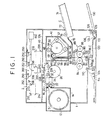
- FIG. l is a sectional view of an embodiment of the image recording apparatus in accordance with the present invention
- an original supporting platen glass 2 is mounted on the top of a housing l.
- the image-forming optical system 200 of an image forming lens moving type which is known per se is disposed under the platen glass 2. More specifically, the image-forming optical system includes an illuminating lamp 208 for scanning the entire area of the lower side of the platen glass 2, mirrors 2l0, 2l8, 220, and an assembly 2l6 of an image-forming lens and a filter unit, mirrors 2l2, 2l4 adapted to move in the same direction as and at a speed which is half the speed of movement of the illuminating lamp 208, and a stationary mirror 222.
- the image-forming optical system 200 in the housing l is separated by a partition wall 224 from other portions in the housing l.
- An aperture 228 is formed in the portion of the partition wall 224 through which the axis 226 of the light reflected from the stationary mirror 222 of the optical system 200 passes, and a shutter 240 is disposed in the aperture 228.
- Upwardly-directed lamps 250 and photosensors 252 associated with these lamps are disposed under the platen glass 2, so as to measure the density of the image on the original carried by the platen glass 2.
- the filter unit 300 of the assembly 2l6 includes a plurality of types of filters such as red filters 302, green filters 304, blue filters 306 and ND filters 308 which are supported by respective solenoids 3l0.
- the filters of each type have different values of transmission factor.
- the arrangement is such that the solenoids 3l0 are selectively activated to put any desired filter or filters 302, 304, 306 into the path of the axis 226.
- a photosensitive developable medium S (hereinafter referred to as "photosensitive medium S"), is stored in the form of a roll l2 which is accommodated by a cartridge l4 which in turn is detachably attached to one side of the housing l.
- a pair of photosensitive developable medium supply rolls 22,22 are disposed in a magazine-adapter dark box 20 located at the outlet l6 for the photosensitive medium S in the cartridge l4, so as to pull and feed a predetermined length of the photosensitive medium S from the roll l2.
- a cutter unit 23 for cutting the photosensitive medium S and a guide plate for guiding the same are disposed ahead of the magazine-adapter dark box 20, i.e. downstream of the dark box 20 as viewed in the direction of movement of the photosensitive medium S.
- a photosensitive medium supporting roll 26 for supporting the photosensitive medium S during the exposure is disposed downstream of the guide plate 24.
- a pair of nip rolls 28 and 30 are held in contact with the supporting roll 26.
- the photosensitive medium S, which has been guided by the guide roll 24 to the position on the supporting roll 26, is held in close contact with the supporting roll 26 by the nip rolls 28, 30 and the portion of the photosensitive medium S positioned between two nip rolls 28 and 30 is exposed to the original through the optical system.
- a heating developing device 40 disposed downstream of the supporting roll 26 is adapted to heat the exposed photosensitive medium S thereby developing a latent image on the photosensitive medium S.
- the heating developing device 40 includes a heat-insulating developing housing 42, a heating roll 44 disposed in the developing housing 42 and maintained at an elevated temperature of about l20°C, and an endless belt 50 going around four belt supporting rolls 46, 47, 48 and 49 and surrounding the heating roll 44 through about 270°, and a nip roll 52 which is held in pressure contact with the supporting roll 49.
- the heating developing device 40 further has a guide device 54 which is adapted for guiding the photosensitive medium S from the supporting roll 26 onto the heating roll 44 and to separate the photosensitive medium S after the heat-development from the heating roll 44, a vertical guide device 58 adapted for guiding the photosensitive medium S sent by the supporting roll 49 and the nip roll 52 towards an outlet 56, and a sensor 60 provided at the outlet 56 and adapted for sensing the leading end of the photosensitive medium S.
- a guide device 54 which is adapted for guiding the photosensitive medium S from the supporting roll 26 onto the heating roll 44 and to separate the photosensitive medium S after the heat-development from the heating roll 44
- a vertical guide device 58 adapted for guiding the photosensitive medium S sent by the supporting roll 49 and the nip roll 52 towards an outlet 56
- a sensor 60 provided at the outlet 56 and adapted for sensing the leading end of the photosensitive medium S.
- An image-receiving sheet member superposing device 70 which is disposed immediately below the outlet 56, has a pair of pressing rolls 62, 64, a nip roll 66 which is held in pressure contact with the pressing roll 64, and a guide member 68 which guides the photosensitive medium S guided by the rolls 64 and 66 to between the pressing rolls 62, 64.
- An image-receiving sheet member feeding device 72 is disposed on one side of the superposing device 70.
- the image-receiving sheet member feeding device 72 is constituted by an image-receiving sheet member feeding cassette 74 projecting from and detachably secured to the housing l, an image-receiving sheet member feeding roll 76 for feeding the image-receiving sheet member C out of the cassette 74, and a guide plate 78 for guiding the image receiving sheet member C fed by the feeding roll 76 to between the pressing roll 64 and the nip roll 66.
- the image-receiving sheet member C has a width which is about 6 mm smaller than that of the photosensitive medium.
- the superposing device 70 is adapted to superpose this image-receiving sheet member C such that the latter is centralized with respect to the photosensitive medium S in the widthwise direction as shown in Figs. 7 and 8.
- An arrow A designates the feed direction of the photosensitive medium S.
- the leading end of the photosensitive medium S is aligned with the leading end of the image-receiving sheet member C as shown in Fig. 7 or positioned several millimeters ahead thereof as shown in Fig. 8.
- the image-receiving sheet member C is smaller than the photosensitive medium S and the former is centralized with respect to the latter in the widthwise direction and the feed direction, the image is recorded over the whole surface of the image-receiving sheet member C.
- a transfer device 88 disposed under the superposing device 70 has a pair of pressurizing nip rolls 80, 82, and a pair of back-up rolls 84, 86 which act to even the distribution of the pressure exerted by the pressurizing nip rolls 80, 82 along the axis of the rolls 80, 82.
- the pressurizing nip rolls 80, 82 are held in contact with each other at a high pressure of about 200 kg/cm2.
- a sheet separating device 90 is disposed under the transfer device 88.
- the sheet separating device 90 has a guide member 92, a first feed roll 94, a second feed roll 96, and a separator belt l02 which goes around guide rolls 98, l00 in such a manner as to make pressure contact only with the photosensitive medium S at both axial ends of the first feed roll 94.
- a photosensitive medium disposal section l04 is provided on one side of the sheet separating device 90, and a fixing device l06 is disposed on the other side of the same.
- the photosensitive medium disposal section l04 is constituted by a guide member l08, a pair of feed rolls ll0, ll2, and a disposal box ll4.
- the photosensitive medium S coming from the sheet separating device 90 and guided by the guide member l08 is introduced by the feed rolls ll0, ll2 into the disposal box ll4.
- the fixing device l06 has a guide member l20, an ultraviolet lamp l24 with a reflecting member l22, and a pair of feed rolls l26, l28.
- the image-receiving sheet member C coming from the sheet separating device 90 and guided by the guide member l20 is irradiated with ultraviolet rays from the lamp l24 for about 5 seconds, so that the image on the image-receiving sheet member C is fixed.
- a tray l30 for receiving the image-receiving sheet member C with fixed image thereon is attached to one side of the housing l so as to project therefrom at a position ahead or downstream of the fixing device l06.
- the image recording apparatus of the present invention further has an exposure amount control panel l50 disposed in a suitable portion of the housing and a controller which is not shown.
- the exposure amount control panel l50 is connected to the photosensors 252 and also to the solenoids 3l0 of the filter unit 300, so as to enable the operator to control the filter unit 300.
- the controller To the controller are connected the exposure amount control panel l50, shutter device 240, driving system (not shown) of the image-forming optical system, cutter unit 23, sensor 60 for sensing the leading end of the photosensitive developable medium, and the superposing device 70, and is adapted to perform the following controlling operation.
- a control system for the filter unit 300 includes amplifiers 400 for receiving the outputs from respective photosensors 252 and A/D converters for receiving the outputs from respective amplifiers 400.
- the control system further has a control circuit 404 for receiving the outputs from respective A/D converters and having a filter table which enables the desired filter to be selected in accordance with the signal to the control circuit 404.
- the output from the control circuit 404 is delivered through a solenoid driving circuit 406 to the solenoids 3l0, whereby the filter unit 300 is controlled.
- an adjustment is conducted so as to position the leading end of the photosensitive medium S in the vicinity of the cutter unit 23 or within the magazine adapter dark box 20.
- the operator pushes a copy start button (not shown) so that the photosensitive medium feed rolls 22 operate to feed the photosensitive medium S until the leading end of the medium S reaches a position 32.
- the lamps 250 are turned on so as to enable the photosensors 252 to measure the density of the image at a plurality of positions on the original.
- the solenoids 3l0 are activated in accordance with the results of measurement so as to bring the desired filter or filters 302, 304, 306 and 308 into the path of the axis 226 of the light beam. If necessary, the operator can put the desired filter or filters into the path of the axis 226 through manual operation of the exposure amount control panel l50.
- the illuminating lamp 208 is turned on and the image-forming optical system 200 commences a predetermined scanning operation, while the shutter device 240 operates to open the path of the light, thereby allowing the photosensitive material S to be exposed. Then, the photosensitive medium S is fed by a length corresponding to the length of the original in the feeding direction and the cutter unit 23 operates to cut the photosensitive medium S.
- the exposed and cut photosensitive medium S is then sent to the heating developing device 40 and is pressed by the endless belt 50 onto the heating roll 44 so as to be heated by the latter up to about l20°C, whereby the image is developed.
- the photosensitive medium S after the development is discharged through the outlet 56. The passage of the leading end of the medium S through the outlet is sensed by the sensor 60.
- the image-receiving sheet member feeding device 72 the image-receiving sheet member C is fed in response to the pushing of the copy start button or in synchronism with the start of the exposure until its leading end comes between the pressing roll 64 and the nip roll 66.
- the image-receiving sheet member superposing device 70 operates so as to superpose the image-receiving sheet member C onto the photosensitive medium S in such a manner that the narrower image-receiving sheet member C is centralized with respect to the wider photosensitive developable medium in the widthwise direction and the leading end of the photosensitive medium S is aligned with the leading end of the image-receiving sheet member C or positioned several millimeters ahead thereof.
- the superposed photosensitive medium S and the image-receiving sheet material C are fed together to the transfer device 88 in which they are pressed to each other at a high pressure of about 200 kg/cm2, whereby the developed image is transferred from the photosensitive medium S to the image-receiving sheet member C.
- the photosensitive medium S is separated by the action of the separating belt l02 in the separating device 90, and is then delivered to the photosensitive developable medium disposal section l04. Meanwhile, the image-receiving sheet member C to which the image has been transferred is introduced into the fixing device l06 where the image is fixed by about a 5-second irradiation with ultraviolet rays. The image-receiving sheet member C with the fixed image thereon is then sent by the rollers l26, l28 to the tray l30.
- the illuminating lamp 208 with the reflecting mirror may be of any type which can radiate rays including visible rays. Examples of such lamps are strobe lamps, flash lamps, tungsten lamps, mercury lamps, halogen lamps such as iodine lamps, xenon lamps, laser beams, CRT sources, plasma, fluorescent lamps and light-emitting diodes. It is also possible to use, in place of the lamp 8, a combination of a microshutter array which makes use of LCD (Liquid Crystal Display) or PLZT (titanium zirconate doped with lanthanum) and a linear or planar light source.
- LCD Liquid Crystal Display
- PLZT titanium zirconate doped with lanthanum
- the heating in the heating developing device 40 which is effected by the heating roll 44 in the described embodiment, may be performed by any other suitable heating means such as a heating belt, a thermal head which incorporates an array of heating elements, electric resistance heating, and a microwave or infrared heating device. It is also possible to heat the photosensitive developable medium S by electric eddy currents generated therein through electromagnetic induction, depending on the nature of the photosensitive developable medium S. The heating also may be effected by dipping the photosensitive developable medium S in a bath of a heated luquid which is inert to the photosensitive developable medium, e.g., fluorine liquid. When such alternative heating means is used, the heating temperature preferably ranges between 80 and 200°C, more preferably between l00 and l60°C.
- the transfer device 88 which is constituted by the pressurizing nip rollers 80, 82 and the back-up rollers 84, 86 in the described embodiment, may be composed of skew rollers or crown rollers which are arranged such that their axes narrowect each other at a suitable angle.
- the fixing device l06 may be of the type which fixes the image by a mere heating or pressing.
- the image recording apparatus has an original carrier platen glass l002 which is mounted through slide bearings l003 on the top of a housing l for reciprocal sliding motion in the directions indicated by arrows l004.
- the platen glass l002 carries an original l005 which is placed thereon with its image surface directed downward.
- An exposure device l200 disposed under the path of sliding movement of the platen glass l002 is adapted for causing the photosensitive medium S to be exposed to the image on the original.
- the exposure device l200 has a light source lamp l204, a light converging lamp l206, and a multi-sided mirror l2l2 which is adapted to be rotated by a motor l208 so as to unidimensionally oscillate the illuminating light beam l2l0 from the light converging lens l206.
- the light source lamp l204, light converging lens l206, and the multi-sided mirror l2l2 are disposed in an illuminating housing l202.
- the exposure device l200 further has an image-forming lens l2l4 for causing the image on the original l005 scanned by the light beam to be focussed on the photosensitive medium S, and a shutter l2l6 for selectively interrupting the optical path between the interior and the exterior of the housing l202.
- the shutter l2l6 is adapted to be driven by a shutter driving solenoid l2l8.
- a pair of nip rolls l026, l02 are disposed in the passage of the photosensitive medium S defined by feed rolls 2024 and guide plates l025 so as to facilitate the passage of the photosensitive medium S over the exposure position l032 where the exposure is effected.
- a pair of roll l030 and a guide plate l03l are disposed downstream of the nip roll l028.
- the operator pushes a copy start button (not shown) so that the photosensitive medium S feed rolls 22 operate to feed the photosensitive medium S.
- the illumination lamp l204 is turned on to illuminate the original.
- the shutter driving solenoid l2l8 operates to open the shutter l2l6 which has been closed and the original supporting platen glass l002 is moved.
- the photosensitive medium S is fed in synchronism with the movement of the platen glass l002, so that the image on the original is projected onto the photosensitive medium S, whereby the latter is exposed.
- the cutter unit 23 When the photosensitive medium S has been fed by a length equal to the stroke of the original, the cutter unit 23 operates to cut the photosensitive medium S. Meanwhile, the shutter l2l6 is closed so as to interrupt the optical path between the interior and the exterior of the housing l202.
- an exposure device l400 of one shot exposure type of the third embodiment is described hereinafter.
- an original carrier glass plate l404 which is mounted on the opening l402 on the top of the housing l.
- the platen glass l404 carries an original l406 which is placed thereon with its image surface directed downwards.
- the exposure device l400 is located under the opening l402 and provided with a plurality of linear light sources l4l0, for example fluorescent lamps, and an illuminating housing l408 having a reflecting inside surface.
- a plurality of linear light sources l4l0 for example fluorescent lamps
- an illuminating housing l408 having a reflecting inside surface.
- An endless belt l424 driven by pulleys l420, l422 is provided between the pair of feed rollers l40l.
- the upper portion of the endless belt l424 is guided by a guide plate l426 so as to locate an exposure position of the photosensitive medium S.
- the shutter l4l6 is opened by the solenoid l4l4 and the light sources l4l0 are lit, so that the entire sensitive surface of the photosensitive medium S is exposured at the same time. Then, the shutter l4l6 is closed by the solenoid l4l4.
- FIG. 6 is a sectional view of the fourth embodiment of the image recording apparatus in accordance with the present invention
- an original supporting platen glass 2002 is mounted on the top of a housing l for reciprocal sliding motion in the directions indicated by arrows 2004.
- the platen glass 2002 therefore, is movable between a position indicated by the solid line and a position indicated by the imaginary line, with the original placed thereon such that the side of the original carrying an image is directed downward.
- a fiber lens array 20l0 is adapted for forming the image of the original on the photosensitive medium S which is disposed at a predetermined position.
- the photosensitive medium S is stored in the form of a roll 20l2 which is accommodated by a cartridge 20l4 which in turn is detachably attached to one side of the housing l.
- a pair of photosensitive medium supply rolls 22,22 are disposed in a magazine-adapter dark box 2020 located at the outlet 20l6 for the photosensitive medium S in the catridge 20l4, so as to pull and feed a predetermined length of the photosensitive developable medium from the roll 20l2.
- the rolls 2022 when approached by the leading end of the photosensitive medium S, move apart from each other to positions shown by the imaginary lines, thus facilitating the passage of the photosensitive medium S.
- a cutter unit 2023 for cutting the photosensitive medium S and a guide plate 2024 for guiding the same are disposed ahead of the magazine-adapter dark box 2020, i.e., downstream of the dark box 2020 as viewed in the direction of movement of the photosensitive medium S.
- a photosensitive medium supporting roll 2026 for supporting the photosensitive medium S during the exposure is disposed downstream of the guide plate 2024.
- a pair of nip rolls 2028 and 2030 are held in contact with the supporting roll 2026.
- the photosensitive medium S which has been guided by the guide plate 2024 to the position on the supporting roll 2026, is held in close contact with the supporting roll 2026 by the nip rolls 2028, 2030 and the portion of the photosensitive medium S positioned between the nip rolls 2028 and 2030 is exposed to the original through the fiber lens array 20l0.
- a superposing device 2l50 is disposed downstream of the photosensitive medium supporting roll 2026.
- the superposing device 2l50 has pressing rolls 2l52, 2l54, a nip roll 2l56 which is held in pressure contact with the pressing roll 2l52, and a pair of nip rolls 2l58, 2l60 for the image-receiving sheet material.
- a guide member 2l62 is disposed between the nip roll 2l56 and the pair of nip rolls 2l58, 2l60, while a horizontal guide plate 2l64 is placed between the pressing roll 2l56 and the photosensitive developable medium supporting roll 2026.
- a sensor 2060 for sensing the leading end of the photosensitive medium S is disposed on a suitable portion of the horizontal guide plate 2l64.
- Upper and lower guide plates 2l68 are disposed on the rear side, i.e., upstream of the nip rolls 2l58, 2l60 for the image-receiving sheet member C.
- An image receiving sheet member supply cassette 2l72 which is provided with a supply roll 2l70, is secured to the housing l so as to project from the housing l at a portion near the inlet ends of the guide plates 2l68.
- the image-receiving sheet member C has a width which is about 6 mm smaller than that of the photosensitive developable medium S.
- the superposing device 2l50 is adapted to superpose the image-receiving sheet member C on the photosensitive medium S such that the sheet member C is centralized with respect to the medium S in the widthwise direction.
- a heating developing device 2040 disposed under the superposing device 2l50 is adapted to heat the exposed photosensitive medium S with the image-receiving sheet member C superposed thereto, thus developing a latent image on the photosensitive medium S.
- the heating developing device 2040 includes a heat-insulating developing housing 2042, a heating roll 2044 disposed in the developing housing 2042 and maintained at an elevated temperature of about l20°C, an endless belt 2050 going around four belt supporting rolls 2046, 2047, 2048 and 2049 and surrounding the heating roll 2044 through about 270°, and a nip roll 2052 which is held in pressure contact with the supporting roll 2049.
- the heating developing device 2040 further has a guide device 2054 which is adapted for guiding the photosensitive medium S from the supporting roll 2026 onto the heating roll 2044 and to separate the photosensitive medium S after the heat-development from the heating roll 2044, and a vertical guide device 2058 adapted for guiding the photosensitive medium S sent by the supporting roll 2049 and the nip roll 2052 towards an outlet 2056.
- a guide device 2054 which is adapted for guiding the photosensitive medium S from the supporting roll 2026 onto the heating roll 2044 and to separate the photosensitive medium S after the heat-development from the heating roll 2044
- a vertical guide device 2058 adapted for guiding the photosensitive medium S sent by the supporting roll 2049 and the nip roll 2052 towards an outlet 2056.
Landscapes
- Physics & Mathematics (AREA)
- General Physics & Mathematics (AREA)
- Photographic Developing Apparatuses (AREA)
Applications Claiming Priority (12)
| Application Number | Priority Date | Filing Date | Title |
|---|---|---|---|
| JP60287492A JPH0677144B2 (ja) | 1985-12-20 | 1985-12-20 | 画像記録装置 |
| JP287492/85 | 1985-12-20 | ||
| JP289703/85 | 1985-12-23 | ||
| JP28970385A JPS62148956A (ja) | 1985-12-23 | 1985-12-23 | 画像記録装置 |
| JP748786A JPS62165661A (ja) | 1986-01-17 | 1986-01-17 | 画像記録装置 |
| JP7487/86 | 1986-01-17 | ||
| JP972486A JPS62166350A (ja) | 1986-01-20 | 1986-01-20 | 画像記録装置 |
| JP9724/86 | 1986-01-20 | ||
| JP1756286A JPS62175755A (ja) | 1986-01-29 | 1986-01-29 | 画像記録装置 |
| JP17562/86 | 1986-01-29 | ||
| JP61051896A JPS62209461A (ja) | 1986-03-10 | 1986-03-10 | 画像記録装置 |
| JP51896/86 | 1986-03-10 |
Publications (3)
| Publication Number | Publication Date |
|---|---|
| EP0227041A2 true EP0227041A2 (fr) | 1987-07-01 |
| EP0227041A3 EP0227041A3 (en) | 1988-10-19 |
| EP0227041B1 EP0227041B1 (fr) | 1992-03-04 |
Family
ID=27548063
Family Applications (1)
| Application Number | Title | Priority Date | Filing Date |
|---|---|---|---|
| EP86117633A Expired EP0227041B1 (fr) | 1985-12-20 | 1986-12-18 | Appareil d'enregistrement d'images |
Country Status (3)
| Country | Link |
|---|---|
| US (1) | US4760426A (fr) |
| EP (1) | EP0227041B1 (fr) |
| DE (1) | DE3684114D1 (fr) |
Cited By (3)
| Publication number | Priority date | Publication date | Assignee | Title |
|---|---|---|---|---|
| EP0240938A3 (en) * | 1986-04-03 | 1989-11-23 | Fuji Photo Film Co., Ltd. | Image recording apparatus |
| EP0261509A3 (en) * | 1986-09-22 | 1990-05-30 | Fuji Photo Film Co., Ltd. | Image recording apparatus |
| EP0326260B1 (fr) * | 1988-01-29 | 1994-08-17 | Sony Corporation | Rouleau de film pourvu de microcapsules photosensibles |
Families Citing this family (22)
| Publication number | Priority date | Publication date | Assignee | Title |
|---|---|---|---|---|
| US5153634A (en) * | 1981-11-12 | 1992-10-06 | The Mead Corporation | Imaging system |
| US4399209A (en) * | 1981-11-12 | 1983-08-16 | The Mead Corporation | Transfer imaging system |
| US4822714A (en) | 1981-11-12 | 1989-04-18 | The Mead Corporation | Transfer imaging system |
| JPS6317451A (ja) * | 1986-07-09 | 1988-01-25 | Fuji Photo Film Co Ltd | 加圧画像形成装置 |
| EP0263609A3 (fr) * | 1986-10-07 | 1990-10-24 | Seiko Epson Corporation | Appareil pour la formation d'images |
| US4827312A (en) * | 1987-01-30 | 1989-05-02 | Fuji Photo Film Co., Ltd. | Image recording apparatus |
| JPS63259663A (ja) * | 1987-04-17 | 1988-10-26 | Fuji Photo Film Co Ltd | 画像記録装置 |
| US4855791A (en) * | 1987-05-29 | 1989-08-08 | Brother Kogyo Kabushiki Kaisha | Sheet roll cartridge and method for loading the same to image recording apparatus |
| US4894680A (en) * | 1987-06-08 | 1990-01-16 | Brother Kogyo Kabushiki Kaisha | Image recording apparatus |
| US5028963A (en) * | 1987-10-15 | 1991-07-02 | Sharp Kabushiki Kaisha | Image forming apparatus |
| US4904573A (en) * | 1987-11-11 | 1990-02-27 | Fuji Photo Film Co., Ltd. | Method for forming a color image and image forming apparatus therefor |
| US5057861A (en) * | 1987-11-28 | 1991-10-15 | Dainippon Screen Mfg. Co. Ltd. | Color image recorder and image projector useful therefor |
| US4819032A (en) * | 1988-01-20 | 1989-04-04 | Fuji Photo Film Co., Ltd. | Belt tensioning mechanism in a thermally developing apparatus |
| JPH01191845A (ja) * | 1988-01-27 | 1989-08-01 | Sharp Corp | 静止露光型画像形成装置 |
| US4992816A (en) * | 1988-09-09 | 1991-02-12 | Fuji Photo Film Co., Ltd. | Image recording apparatus and method |
| JPH0274943A (ja) * | 1988-09-12 | 1990-03-14 | Brother Ind Ltd | 画像形成装置 |
| JPH0830889B2 (ja) * | 1989-09-22 | 1996-03-27 | シャープ株式会社 | 画像形成装置 |
| US5010360A (en) * | 1990-09-27 | 1991-04-23 | Brother Kogyo Kabushiki Kaisha | Image forming apparatus |
| JPH05145706A (ja) * | 1991-03-05 | 1993-06-11 | Canon Inc | 画像読取装置 |
| WO1992022854A1 (fr) * | 1991-06-17 | 1992-12-23 | Seiko Epson Corporation | Appareil de developpement thermique |
| EP0546190A1 (fr) * | 1991-06-27 | 1993-06-16 | Seiko Epson Corporation | Appareil de formation d'image |
| JP2001324789A (ja) * | 2000-05-15 | 2001-11-22 | Fuji Photo Film Co Ltd | 画像記録方法及び画像記録装置 |
Family Cites Families (9)
| Publication number | Priority date | Publication date | Assignee | Title |
|---|---|---|---|---|
| JPS57179836A (en) * | 1981-04-28 | 1982-11-05 | Fuji Photo Film Co Ltd | Photosensitive material |
| US4501809A (en) * | 1981-07-17 | 1985-02-26 | Mitsubishi Paper Mills, Ltd. | Photosetting microcapsules and photo- and pressure-sensitive recording sheet |
| US4399209A (en) * | 1981-11-12 | 1983-08-16 | The Mead Corporation | Transfer imaging system |
| JPS59181346A (ja) * | 1983-03-31 | 1984-10-15 | Fuji Photo Film Co Ltd | 熱現像転写方法 |
| JPS60117089A (ja) * | 1983-11-28 | 1985-06-24 | Matsushita Electric Ind Co Ltd | 熱交換器の製造方法 |
| JPS60121284A (ja) * | 1983-12-06 | 1985-06-28 | Kao Corp | 金属洗浄剤組成物 |
| EP0163300B1 (fr) * | 1984-05-31 | 1992-08-19 | Fuji Photo Film Co., Ltd. | Dispositif et méthode de transfert d'images |
| US4622282A (en) * | 1985-02-20 | 1986-11-11 | The Mead Corporation | Photographic method for forming images on plain paper |
| US4624560A (en) * | 1985-10-25 | 1986-11-25 | Itt Corporation | Capsule rupture printing system |
-
1986
- 1986-12-17 US US06/942,654 patent/US4760426A/en not_active Expired - Lifetime
- 1986-12-18 DE DE8686117633T patent/DE3684114D1/de not_active Expired - Lifetime
- 1986-12-18 EP EP86117633A patent/EP0227041B1/fr not_active Expired
Cited By (4)
| Publication number | Priority date | Publication date | Assignee | Title |
|---|---|---|---|---|
| EP0240938A3 (en) * | 1986-04-03 | 1989-11-23 | Fuji Photo Film Co., Ltd. | Image recording apparatus |
| EP0261509A3 (en) * | 1986-09-22 | 1990-05-30 | Fuji Photo Film Co., Ltd. | Image recording apparatus |
| EP0486471A1 (fr) * | 1986-09-22 | 1992-05-20 | Fuji Photo Film Co., Ltd. | Appareil d'enregistrement d'images |
| EP0326260B1 (fr) * | 1988-01-29 | 1994-08-17 | Sony Corporation | Rouleau de film pourvu de microcapsules photosensibles |
Also Published As
| Publication number | Publication date |
|---|---|
| DE3684114D1 (de) | 1992-04-09 |
| EP0227041B1 (fr) | 1992-03-04 |
| EP0227041A3 (en) | 1988-10-19 |
| US4760426A (en) | 1988-07-26 |
Similar Documents
| Publication | Publication Date | Title |
|---|---|---|
| EP0227041B1 (fr) | Appareil d'enregistrement d'images | |
| US4737822A (en) | Image recording apparatus and method | |
| US4799085A (en) | Image recording apparatus and method | |
| US4783683A (en) | Image recording apparatus | |
| US5572285A (en) | Image forming apparatus | |
| JPS62148956A (ja) | 画像記録装置 | |
| EP0240938A2 (fr) | Appareil d'enregistrement d'images | |
| US4809599A (en) | Image forming apparatus with microcapsule pressure rupture | |
| JPH03198056A (ja) | 熱定着装置 | |
| JPH0677144B2 (ja) | 画像記録装置 | |
| JPS62249163A (ja) | 画像記録装置 | |
| JPS62270958A (ja) | 画像記録装置 | |
| US4809598A (en) | Image forming apparatus with variable transfer pressure | |
| JPS62270957A (ja) | 画像記録装置 | |
| JPS62232652A (ja) | 加圧画像形成装置 | |
| JPS62209461A (ja) | 画像記録装置 | |
| JPH01134445A (ja) | 画像記録装置 | |
| JPS6370253A (ja) | 加圧画像形成装置 | |
| JP2921009B2 (ja) | 画像形成装置 | |
| JPS6317440A (ja) | 画像記録装置 | |
| JPH03142456A (ja) | 画像形成装置 | |
| JPS62165661A (ja) | 画像記録装置 | |
| JPS63259632A (ja) | 画像形成装置 | |
| JPH04156457A (ja) | 画像形成装置 | |
| JPS62165662A (ja) | 画像記録装置 |
Legal Events
| Date | Code | Title | Description |
|---|---|---|---|
| PUAI | Public reference made under article 153(3) epc to a published international application that has entered the european phase |
Free format text: ORIGINAL CODE: 0009012 |
|
| AK | Designated contracting states |
Kind code of ref document: A2 Designated state(s): DE FR GB |
|
| PUAL | Search report despatched |
Free format text: ORIGINAL CODE: 0009013 |
|
| RHK1 | Main classification (correction) |
Ipc: G03G 15/28 |
|
| AK | Designated contracting states |
Kind code of ref document: A3 Designated state(s): DE FR GB |
|
| 17P | Request for examination filed |
Effective date: 19881209 |
|
| 17Q | First examination report despatched |
Effective date: 19890505 |
|
| GRAA | (expected) grant |
Free format text: ORIGINAL CODE: 0009210 |
|
| AK | Designated contracting states |
Kind code of ref document: B1 Designated state(s): DE FR GB |
|
| REF | Corresponds to: |
Ref document number: 3684114 Country of ref document: DE Date of ref document: 19920409 |
|
| ET | Fr: translation filed | ||
| PLBE | No opposition filed within time limit |
Free format text: ORIGINAL CODE: 0009261 |
|
| STAA | Information on the status of an ep patent application or granted ep patent |
Free format text: STATUS: NO OPPOSITION FILED WITHIN TIME LIMIT |
|
| 26N | No opposition filed | ||
| REG | Reference to a national code |
Ref country code: GB Ref legal event code: IF02 |
|
| PGFP | Annual fee paid to national office [announced via postgrant information from national office to epo] |
Ref country code: FR Payment date: 20051024 Year of fee payment: 20 |
|
| PGFP | Annual fee paid to national office [announced via postgrant information from national office to epo] |
Ref country code: GB Payment date: 20051216 Year of fee payment: 20 |
|
| PGFP | Annual fee paid to national office [announced via postgrant information from national office to epo] |
Ref country code: DE Payment date: 20060120 Year of fee payment: 20 |
|
| PG25 | Lapsed in a contracting state [announced via postgrant information from national office to epo] |
Ref country code: GB Free format text: LAPSE BECAUSE OF EXPIRATION OF PROTECTION Effective date: 20061217 |
|
| REG | Reference to a national code |
Ref country code: GB Ref legal event code: PE20 |