EP0227063B1 - Dispositif de blocage de corde - Google Patents
Dispositif de blocage de corde Download PDFInfo
- Publication number
- EP0227063B1 EP0227063B1 EP86117747A EP86117747A EP0227063B1 EP 0227063 B1 EP0227063 B1 EP 0227063B1 EP 86117747 A EP86117747 A EP 86117747A EP 86117747 A EP86117747 A EP 86117747A EP 0227063 B1 EP0227063 B1 EP 0227063B1
- Authority
- EP
- European Patent Office
- Prior art keywords
- cord
- tightening device
- side walls
- teeth
- retainer
- Prior art date
- Legal status (The legal status is an assumption and is not a legal conclusion. Google has not performed a legal analysis and makes no representation as to the accuracy of the status listed.)
- Expired - Lifetime
Links
Images


Classifications
-
- A—HUMAN NECESSITIES
- A45—HAND OR TRAVELLING ARTICLES
- A45F—TRAVELLING OR CAMP EQUIPMENT: SACKS OR PACKS CARRIED ON THE BODY
- A45F3/00—Travelling or camp articles; Sacks or packs carried on the body
- A45F3/12—Shoulder-pads
-
- B—PERFORMING OPERATIONS; TRANSPORTING
- B65—CONVEYING; PACKING; STORING; HANDLING THIN OR FILAMENTARY MATERIAL
- B65D—CONTAINERS FOR STORAGE OR TRANSPORT OF ARTICLES OR MATERIALS, e.g. BAGS, BARRELS, BOTTLES, BOXES, CANS, CARTONS, CRATES, DRUMS, JARS, TANKS, HOPPERS, FORWARDING CONTAINERS; ACCESSORIES, CLOSURES, OR FITTINGS THEREFOR; PACKAGING ELEMENTS; PACKAGES
- B65D63/00—Flexible elongated elements, e.g. straps, for bundling or supporting articles
- B65D63/10—Non-metallic straps, tapes, or bands; Filamentary elements, e.g. strings, threads or wires; Joints between ends thereof
- B65D63/14—Joints produced by application of separate securing members
- B65D63/16—Joints using buckles, wedges, or like locking members attached to the end of the element
-
- A—HUMAN NECESSITIES
- A45—HAND OR TRAVELLING ARTICLES
- A45C—PURSES; LUGGAGE; HAND CARRIED BAGS
- A45C13/00—Details; Accessories
- A45C13/30—Straps; Bands
-
- F—MECHANICAL ENGINEERING; LIGHTING; HEATING; WEAPONS; BLASTING
- F16—ENGINEERING ELEMENTS AND UNITS; GENERAL MEASURES FOR PRODUCING AND MAINTAINING EFFECTIVE FUNCTIONING OF MACHINES OR INSTALLATIONS; THERMAL INSULATION IN GENERAL
- F16G—BELTS, CABLES, OR ROPES, PREDOMINANTLY USED FOR DRIVING PURPOSES; CHAINS; FITTINGS PREDOMINANTLY USED THEREFOR
- F16G11/00—Means for fastening cables or ropes to one another or to other objects; Caps or sleeves for fixing on cables or ropes
- F16G11/10—Quick-acting fastenings; Clamps holding in one direction only
- F16G11/101—Quick-acting fastenings; Clamps holding in one direction only deforming the cable by moving a part of the fastener
-
- F—MECHANICAL ENGINEERING; LIGHTING; HEATING; WEAPONS; BLASTING
- F16—ENGINEERING ELEMENTS AND UNITS; GENERAL MEASURES FOR PRODUCING AND MAINTAINING EFFECTIVE FUNCTIONING OF MACHINES OR INSTALLATIONS; THERMAL INSULATION IN GENERAL
- F16G—BELTS, CABLES, OR ROPES, PREDOMINANTLY USED FOR DRIVING PURPOSES; CHAINS; FITTINGS PREDOMINANTLY USED THEREFOR
- F16G11/00—Means for fastening cables or ropes to one another or to other objects; Caps or sleeves for fixing on cables or ropes
- F16G11/10—Quick-acting fastenings; Clamps holding in one direction only
- F16G11/105—Clamps holding in one direction only
- F16G11/106—Clamps holding in one direction only using a toothed surface
-
- Y—GENERAL TAGGING OF NEW TECHNOLOGICAL DEVELOPMENTS; GENERAL TAGGING OF CROSS-SECTIONAL TECHNOLOGIES SPANNING OVER SEVERAL SECTIONS OF THE IPC; TECHNICAL SUBJECTS COVERED BY FORMER USPC CROSS-REFERENCE ART COLLECTIONS [XRACs] AND DIGESTS
- Y10—TECHNICAL SUBJECTS COVERED BY FORMER USPC
- Y10T—TECHNICAL SUBJECTS COVERED BY FORMER US CLASSIFICATION
- Y10T24/00—Buckles, buttons, clasps, etc.
- Y10T24/37—Drawstring, laced-fastener, or separate essential cooperating device therefor
- Y10T24/3703—Includes separate device for holding drawn portion of lacing
- Y10T24/3713—Includes separate device for holding drawn portion of lacing having relatively movable holding components or surfaces
-
- Y—GENERAL TAGGING OF NEW TECHNOLOGICAL DEVELOPMENTS; GENERAL TAGGING OF CROSS-SECTIONAL TECHNOLOGIES SPANNING OVER SEVERAL SECTIONS OF THE IPC; TECHNICAL SUBJECTS COVERED BY FORMER USPC CROSS-REFERENCE ART COLLECTIONS [XRACs] AND DIGESTS
- Y10—TECHNICAL SUBJECTS COVERED BY FORMER USPC
- Y10T—TECHNICAL SUBJECTS COVERED BY FORMER US CLASSIFICATION
- Y10T24/00—Buckles, buttons, clasps, etc.
- Y10T24/39—Cord and rope holders
- Y10T24/3969—Sliding part or wedge
-
- Y—GENERAL TAGGING OF NEW TECHNOLOGICAL DEVELOPMENTS; GENERAL TAGGING OF CROSS-SECTIONAL TECHNOLOGIES SPANNING OVER SEVERAL SECTIONS OF THE IPC; TECHNICAL SUBJECTS COVERED BY FORMER USPC CROSS-REFERENCE ART COLLECTIONS [XRACs] AND DIGESTS
- Y10—TECHNICAL SUBJECTS COVERED BY FORMER USPC
- Y10T—TECHNICAL SUBJECTS COVERED BY FORMER US CLASSIFICATION
- Y10T24/00—Buckles, buttons, clasps, etc.
- Y10T24/39—Cord and rope holders
- Y10T24/3969—Sliding part or wedge
- Y10T24/3976—Sliding ball
Definitions
- the present invention relates to a cord tightening device of synthetic resin for tightening cords or strings on various articles such as anoraks, rucksacks, shopping bags, life jackets, and other bags and pouches having openings to be closed with cords or strings.
- the present invention particularly relates to a cord tightening device in accordance with the preamble of claim 1.
- a cord tightening device of this type is disclosed in FR-A 1 573 320.
- a cord to be tightened by such a cord tightening device has its end portions inserted through the body, one between the slider and one of the side walls and the other between the slider and the other side wall.
- the body is pulled so that the slider is moved toward the narrower opening, wedging cord portions against the side walls with the serrations of the slider.
- the present invention seeks to provide a cord tightening device of a simple and inexpensive construction which enables easy insertion of the cord.
- this object is realized with a cord tightening device according to the preamble of claim 1, characterized in that said face plate has a pair of cord insertion slots defined therein one on each side of said guide groove and located inwardly of said side walls, respectively, each of said cord insertion slots comprises a pair of spaced holes and a straight slit communicating between said holes.
- An end of the cord may first be inserted successively through the openings of the body and the holes of the cord insertion slot with an intermediate cord portion left over the face plate, then the cord is pulled in opposite directions to force the intermediate cord portion through the insertion slot into the body.
- the cord tightening device 10 generally comprises a body 11 and a slider 12 slidably disposed in the body 11.
- the body 11 and the slider 12 are injection-molded of synthetic resin.
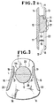
- the body 11 is of a hollow structure composed of a pair of parallel faces and back plates 13, 14 spaced from each other and integrally interconnected by a pair of side walls 15, 16 spaced from each other.
- the side walls 15, 16 converge toward each other upwardly (Figure 3) and terminate at a narrower opening 17 defined between the upper ends of the face and back plates 13, 14.
- the side walls 15, 16 diverge away from each other downwardly (Figure 3) and terminate at a wider opening 18 defined between the lower ends of the face and back plates 13, 14.
- the side walls 15, 16 have shorter upper straight portions 19 extending substantially parallel to each other and longer lower inclined portions 20 extending downwardly from the upper portions 19, respectively, and diverging progressively away from each other in the downward direction.
- the side walls 15, 16 have a series of teeth or serrations 21 on inner surfaces of the lower portions 20 near the upper portions 19.
- the face plate 13 has a vertically elongate guide groove 22 lying at equal distances from the side walls 15, 16 and extending from a position between the upper portions 19 of the side walls 15, 16 downwardly toward a position at the wider opening 18.
- the slider 12 in the body 11 is slidable along the guide groove 22.
- the slider 12 comprises a substantially circular retainer 23 for securely pressing portions of a cord C ( Figure 4) against the side walls 15, 16 and a knob 24 integral with the retainer 23 and projecting through the guide groove 22 above the outer surface of the face plate 13.
- the knob 24 is slidably fitted in the guide groove 22 and has a pair of outer parallel edges 25 slidably engaging inner parallel edges 26 of the face plate 13 which define the guide groove 22 therebetween.
- the knob 24 has on its upper surface a plurality of parallel ridges 27 for providing good frictional contact with the user's finger in moving the slider 12 along the guide groove 22.
- the substantially circular retainer 23 has a series of step-like teeth or serrations 28 on each of diametrically opposite peripheral surfaces thereof which face the side walls 15, 16.
- the teeth or serrations 28 are located above and below a horizontal central line L of the retainer 23, which extends substantially perpendicularly to the direction in which the slider 12 is slidable along the guide groove 22.
- the teeth 28 serve to bite into the portions of the cord C to keep the cord C securely in position with respect to the body 11 against undesired slippage.
- Each of the step-like teeth 23 is defined by a surface extending parallel to the central line L and another surface extending perpendicularly to the central line L This configuration of the step-like teeth 23 allows the body 11 and the slider 12 to be injection-molded together in one mold assembly, as will be described later on.
- the end portions of the cord C to be tightened are arranged within the body 11, one between the side wall 15 and the retainer 23 and the other between the side wall 16 and the retainer 23.
- portions of the cord C are gripped between the inner surfaces of the side walls 15, 16 and the teeth 28 which bite into the cord portions.
- the teeth 21 on the side walls 15, 16 are preferable since they also bite into the cord portions to retain the cord C firmly in position for greater protection against unwanted slippage of the cord C in the body 11.
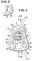
- the face plate 13 of the body 11 has a pair of laterally spaced cord insertion slots 31, 32 defined therein one on each side of the guide groove 22 and positioned slightly inwardly of the side walls 15, 16.
- Each of the cord insertion slots 31, 32 includes a pair of upper and lower holes 33, 34 spaced vertically from each other and located in the narrower and wider openings 17, 18, respectively, and a narrow straight slit 35 communicating between the upper and lower holes 33, 34 and extending substantially along one of the side walls 15, 16.
- an end of the cord C may first be inserted successively through the holes 33, 34 and the openings 17, 18 with an intermediate cord portion left over the face plate 13, as shown in Figure 1.
- the cord C is pulled in the opposite directions indicated by the arrows D, E to force the intermediate cord portion through the slit 35 into the body 11.
- the relatively thick cord C can therefore be inserted in the body 11 quite easily.
- the cord C, once inserted in the body 11, is securely retained therein against dislodgement through the slit 35 because the slit 35 is narrow.
- Each of the holes 33, 34 is substantially circular in shape. However, as shown in Figure 5, they may be of an elongate shape 36 which is elongated in the direction along the slit 35.
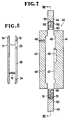
- Figures 7 and 8 show a mold assembly for injection-molding a cord tightening device in accordance with the present invention.
- the mold assembly generally designated by the reference numeral 40, comprises a first mold member 41, a second mold member 42, a first core 43, and a second core 44.
- the first mold member 41 has a cavity 45 for forming the face plate 13 of the body 11, another cavity 46 for forming the knob 24, and a projection 47 for forming the guide groove 22 in the face plate 13.
- the second mold member 42 has a cavity 48 for forming the back plate 14 of the body 11 and a gate 49 communicating with the cavity 48 for pouring molten synthetic resin into the cavity 48.
- the first core member 43 is movable into a position between the first and second mold members 41, 42 and has a substantially semicircular cavity 50 for forming one half of the retainer 23 of the slider 12.
- the cavity 50 is defined centrally in an end of the first core member 43 which is insertable between the first and second mold members 41, 42.
- the end of the first core member 43 is of a bifurcated shape composed of a pair of parallel, spaced webs 51 defining the cavity 50 therebetween.
- the semicircular edge which defines the cavity 50 has a series of step-like teeth or serrations 52 on each of its opposite surfaces for forming the teeth or serrations 28 on the half of the retainer 23 which is positioned below the central line L ( Figure 3).
- the first core member 43 also has a pair of inclined recessed side surfaces 53 for shaping the lower diverging portions 20 of the side walls 15, 16 of the body 11.
- the inclined side surfaces 53 have respective series of teeth or serrations 54 at their ends near the cavity 50.
- the second core member 44 is movable into a position between the first and second mold members 41, 42 and has a substantially semicircular cavity 55 for forming the other half of the retainer 23 of the slider 12.
- the cavity 55 is defined centrally in an end of the second core member 44 which is insertable between the first and second mold members 41, 42.
- the end of the second core member 44 is of a bifurcated shape composed of a pair of parallel, spaced webs 56 defining the cavity 55 therebetween.
- the semicircular edge which defines the cavity 55 has a series of step-like teeth or serrations 57 on each of its opposite surfaces for forming the teeth or serrations 28 on the half of the retainer 23 which is positioned above the central line L ( Figure 3).
- the second core member 44 also has a pair of parallel recessed side surfaces 58 for shaping the upper parallel portion 19 of the side walls 15, 16 of the body 11.
- the webs 51, 56 of the first and second core members 43, 44 serve to separate the face and back platesl3, 14 from the slider 12 after the cord tightening device has been injection-molded by the mold assembly 40.
- One of the webs 51 and one of the webs 56 have openings 59, 60, respectively, which will communicate with the cavity 46 of the first mold member 41 when the mold assembly 40 is completed.
- the openings 59, 60 provide a path for introducing molten synthetic resin into the cavities 50, 55.
- the first and second mold members 41, 42 are brougth together, and the first and second core members 43, 44 are inserted into the combined cavities 45, 48 from upper and lower ends, respectively, thereof until the distal ends of the first and second core members 43, 44 engage each other.
- the semicircular cavities 50, 55 of the first and second core members 43, 44 are combined into a substantially circular cavity.
- molten synthetic resin is poured through the gate 49 into the cavities 48, 45, 46, 50, 55.
- the first and second core members 43, 44 are pulled out, and the first and second mold members 41, 42 are separated from each oth-. er, thus removing the molded cord tightening device.
- the step-like teeth or serrations 52, 57 of the first and second core members 43, 44 have surfaces parallel and normal to the direction in which the core members 43, 44 are moved toward and away from each other. Therefore, the step-like teeth or serrations 52, 57 do not obstruct the separation of the first and second core members 43, 44 from the molded retainer 23 of the slider 12. As a consequence, the slider 12 and the body 11 can be simultaneously injection-molded by the single mold assembly 40. The cord tightening device 10 can thus be manufactured simply and inexpensively..
- the cord tightening device allows easy insertion of the cord C therethrough even if the cord C is relatively thick.
Landscapes
- Engineering & Computer Science (AREA)
- General Engineering & Computer Science (AREA)
- Mechanical Engineering (AREA)
- Moulds For Moulding Plastics Or The Like (AREA)
- Injection Moulding Of Plastics Or The Like (AREA)
- Portable Outdoor Equipment (AREA)
- Buckles (AREA)
- Purses, Travelling Bags, Baskets, Or Suitcases (AREA)
- Package Frames And Binding Bands (AREA)
Claims (8)
Applications Claiming Priority (4)
| Application Number | Priority Date | Filing Date | Title |
|---|---|---|---|
| JP201839/85U | 1985-12-25 | ||
| JP20183985U JPH0114174Y2 (fr) | 1985-12-25 | 1985-12-25 | |
| JP1985204493U JPS6494Y2 (fr) | 1985-12-28 | 1985-12-28 | |
| JP204493/85U | 1985-12-28 |
Publications (3)
| Publication Number | Publication Date |
|---|---|
| EP0227063A2 EP0227063A2 (fr) | 1987-07-01 |
| EP0227063A3 EP0227063A3 (en) | 1987-08-26 |
| EP0227063B1 true EP0227063B1 (fr) | 1990-05-02 |
Family
ID=26513026
Family Applications (1)
| Application Number | Title | Priority Date | Filing Date |
|---|---|---|---|
| EP86117747A Expired - Lifetime EP0227063B1 (fr) | 1985-12-25 | 1986-12-19 | Dispositif de blocage de corde |
Country Status (8)
| Country | Link |
|---|---|
| US (1) | US4788755A (fr) |
| EP (1) | EP0227063B1 (fr) |
| KR (1) | KR900010361Y1 (fr) |
| AU (1) | AU580199B2 (fr) |
| DE (1) | DE3670896D1 (fr) |
| HK (1) | HK30792A (fr) |
| MY (1) | MY100745A (fr) |
| SG (1) | SG27592G (fr) |
Families Citing this family (21)
| Publication number | Priority date | Publication date | Assignee | Title |
|---|---|---|---|---|
| JPH0246731Y2 (fr) * | 1986-06-02 | 1990-12-10 | ||
| US4967824A (en) * | 1989-06-16 | 1990-11-06 | Hunter Douglas, Inc. | Cord equalizer |
| FR2706743B1 (fr) * | 1993-06-21 | 1995-08-25 | Salomon Sa | |
| US5471713A (en) * | 1994-03-23 | 1995-12-05 | Alter; Allan | Cord retaining and fastening device |
| US6112379A (en) | 1997-01-17 | 2000-09-05 | Fernandez; Eduardo Roberto | Fastener device for strings |
| USD536173S1 (en) | 1999-06-04 | 2007-02-06 | Snugz Usa, Inc. | Lanyard connector surface |
| US6711785B1 (en) * | 1999-06-04 | 2004-03-30 | Bryan K. Hicks | Lanyard connector and system |
| USD539697S1 (en) | 1999-06-04 | 2007-04-03 | Snugz Usa, Inc. | Lanyard connector |
| USD507110S1 (en) | 1999-06-04 | 2005-07-12 | Bryan K. Hicks | Lanyard connector |
| US6185798B1 (en) * | 1999-07-06 | 2001-02-13 | Huy That Anh Ton | Shoelace fastener |
| US6457214B1 (en) * | 2000-10-13 | 2002-10-01 | Robert O. Boden | Tamper-resistant cord lock apparatus |
| FR2975263B1 (fr) * | 2011-05-16 | 2014-04-11 | Salomon Sas | Dispositif de blocage de brins de fil |
| US20130001962A1 (en) * | 2011-07-01 | 2013-01-03 | Troy Wheelwright | Child proof cupboard closure |
| USD766709S1 (en) * | 2014-01-17 | 2016-09-20 | Nifco Inc. | String end stopper |
| DE102016106958A1 (de) * | 2016-04-14 | 2017-10-19 | NITRO Snowboards Entwicklungs-GmbH | Schnürsenkelsicherung für Innenschuh |
| US10441063B2 (en) * | 2016-07-22 | 2019-10-15 | Ccl Label, Inc. | Spin and twist resistant clip and badge holder and lanyard assembly |
| EP3595480A4 (fr) * | 2017-03-13 | 2020-12-02 | Xpand Inc. | Verrouillage de lacet de chaussures et système et procédé de laçage de chaussures |
| US20200248781A1 (en) * | 2019-02-01 | 2020-08-06 | Craig W. Patterson | Cinching device |
| US11510460B2 (en) * | 2019-10-03 | 2022-11-29 | Nike, Inc. | Dynamic lacing system |
| US12044040B2 (en) * | 2021-04-02 | 2024-07-23 | Brady Worldwide, Inc. | Cable lockout device |
| US12320163B2 (en) * | 2022-06-29 | 2025-06-03 | Brady Worldwide, Inc. | Multicable lockout device |
Family Cites Families (14)
| Publication number | Priority date | Publication date | Assignee | Title |
|---|---|---|---|---|
| US307806A (en) * | 1884-11-11 | Cord or strap fastener | ||
| DE384260C (de) * | 1922-03-14 | 1923-11-08 | Willy Kruegel | Klemmschloss fuer Rucksackschnuere u. dgl. |
| US1560661A (en) * | 1925-06-08 | 1925-11-10 | Carlson Frank William | Pump-rod and casing handling device |
| DE607508C (de) * | 1932-09-13 | 1934-12-29 | Hans Nowrath | Schnuersenkelhalter |
| US2199758A (en) * | 1939-07-27 | 1940-05-07 | Clarence J Rio | Shoelace fastener |
| US2200895A (en) * | 1939-09-13 | 1940-05-14 | Clarence J Rio | Shoestring fastener |
| DE891065C (de) * | 1951-11-03 | 1953-09-24 | Erwin Neubauer | Verschluss fuer Schnuersenkel |
| US3132390A (en) * | 1961-10-05 | 1964-05-12 | Ogden W Boden | Slide clamp |
| DE1760525C2 (de) * | 1967-06-16 | 1983-12-01 | Bengtsson, Sigurd Walter, Göteborg | Klemmvorrichtung, die auf zwei Schnüren verschiebbar angeordnet ist |
| US3861003A (en) * | 1973-06-22 | 1975-01-21 | Ogden W Boden | Cord locking device with safety latch |
| JPS52648A (en) * | 1975-06-12 | 1977-01-06 | Komatsu Mfg Co Ltd | Method of desalting crop field |
| US4059333A (en) * | 1977-01-05 | 1977-11-22 | Amp Incorporated | Electrical connector |
| US4102019A (en) * | 1977-03-07 | 1978-07-25 | Boden Ogden W | Locking assemblies which maintain bow loops in cords |
| BE900151A (fr) * | 1984-07-12 | 1984-11-05 | Spiral S P R L | Dispositif destine a etre associe a un lien pour former une boucle de dimension reglable. |
-
1986
- 1986-12-09 MY MYPI86000182A patent/MY100745A/en unknown
- 1986-12-15 AU AU66517/86A patent/AU580199B2/en not_active Ceased
- 1986-12-19 EP EP86117747A patent/EP0227063B1/fr not_active Expired - Lifetime
- 1986-12-19 DE DE8686117747T patent/DE3670896D1/de not_active Expired - Lifetime
- 1986-12-24 KR KR2019860021152U patent/KR900010361Y1/ko not_active Expired
- 1986-12-24 US US06/946,714 patent/US4788755A/en not_active Expired - Lifetime
-
1992
- 1992-03-09 SG SG275/92A patent/SG27592G/en unknown
- 1992-04-23 HK HK307/92A patent/HK30792A/en not_active IP Right Cessation
Also Published As
| Publication number | Publication date |
|---|---|
| SG27592G (en) | 1992-05-15 |
| US4788755A (en) | 1988-12-06 |
| KR900010361Y1 (ko) | 1990-11-15 |
| KR870009397U (ko) | 1987-07-07 |
| HK30792A (en) | 1992-05-01 |
| DE3670896D1 (de) | 1990-06-07 |
| EP0227063A3 (en) | 1987-08-26 |
| AU6651786A (en) | 1987-07-16 |
| AU580199B2 (en) | 1989-01-05 |
| MY100745A (en) | 1991-02-14 |
| EP0227063A2 (fr) | 1987-07-01 |
Similar Documents
| Publication | Publication Date | Title |
|---|---|---|
| HK30792A (en) | Cord tightening device | |
| CN1161053C (zh) | 可重复闭合的拉链组件及热塑性塑料袋 | |
| KR900007522Y1 (ko) | 버클 조립체 | |
| EP0877567B1 (fr) | Ensemble fermeture refermable | |
| EP0636812A1 (fr) | Dispositif de blocage de corde | |
| US4924561A (en) | Single-fin fastener | |
| JPH07108241B2 (ja) | 紐のリテ−ナ | |
| EP0287060B1 (fr) | Tirette pour curseur de fermeture à glissière | |
| US6170133B1 (en) | Buckle | |
| JPH06343506A (ja) | 紐締具 | |
| BG98991A (bg) | Приспособление за защипване,по-специално за затваряне на торбичка | |
| GB2183405A (en) | Strain relief bushing for clamping an electrical cable | |
| US4836590A (en) | Security seal with tampering indicator | |
| EP0248290B1 (fr) | Dispositif de blocage de corde | |
| US6728997B1 (en) | Closure device | |
| EP0383603B1 (fr) | Fermeture à glissière | |
| US4474043A (en) | Adjustable split-ring key tag | |
| EP0041237B1 (fr) | Butée d'arrêt supérieure en forme de pont pour fermetures à glissière | |
| JP2001259030A (ja) | クランプ及び医療用具 | |
| US4429557A (en) | Key holder | |
| GB2178790A (en) | Cord clamp | |
| US3659776A (en) | Bag handle | |
| JPH026812Y2 (fr) | ||
| JP3019914U (ja) | 紐止め具 | |
| JPH024090Y2 (fr) |
Legal Events
| Date | Code | Title | Description |
|---|---|---|---|
| PUAI | Public reference made under article 153(3) epc to a published international application that has entered the european phase |
Free format text: ORIGINAL CODE: 0009012 |
|
| AK | Designated contracting states |
Kind code of ref document: A2 Designated state(s): DE FR GB IT |
|
| PUAL | Search report despatched |
Free format text: ORIGINAL CODE: 0009013 |
|
| AK | Designated contracting states |
Kind code of ref document: A3 Designated state(s): DE FR GB IT |
|
| 17P | Request for examination filed |
Effective date: 19871123 |
|
| 17Q | First examination report despatched |
Effective date: 19890120 |
|
| GRAA | (expected) grant |
Free format text: ORIGINAL CODE: 0009210 |
|
| AK | Designated contracting states |
Kind code of ref document: B1 Designated state(s): DE FR GB IT |
|
| ITF | It: translation for a ep patent filed | ||
| REF | Corresponds to: |
Ref document number: 3670896 Country of ref document: DE Date of ref document: 19900607 |
|
| ET | Fr: translation filed | ||
| PLBE | No opposition filed within time limit |
Free format text: ORIGINAL CODE: 0009261 |
|
| STAA | Information on the status of an ep patent application or granted ep patent |
Free format text: STATUS: NO OPPOSITION FILED WITHIN TIME LIMIT |
|
| 26N | No opposition filed | ||
| ITTA | It: last paid annual fee | ||
| ITPR | It: changes in ownership of a european patent |
Owner name: CAMBIO RAGIONE SOCIALE;YKK CORPORATION |
|
| REG | Reference to a national code |
Ref country code: FR Ref legal event code: CD |
|
| PGFP | Annual fee paid to national office [announced via postgrant information from national office to epo] |
Ref country code: DE Payment date: 19950131 Year of fee payment: 9 |
|
| PG25 | Lapsed in a contracting state [announced via postgrant information from national office to epo] |
Ref country code: DE Effective date: 19960903 |
|
| REG | Reference to a national code |
Ref country code: GB Ref legal event code: IF02 |
|
| PGFP | Annual fee paid to national office [announced via postgrant information from national office to epo] |
Ref country code: FR Payment date: 20031210 Year of fee payment: 18 |
|
| PGFP | Annual fee paid to national office [announced via postgrant information from national office to epo] |
Ref country code: GB Payment date: 20031217 Year of fee payment: 18 |
|
| PG25 | Lapsed in a contracting state [announced via postgrant information from national office to epo] |
Ref country code: GB Free format text: LAPSE BECAUSE OF NON-PAYMENT OF DUE FEES Effective date: 20041219 |
|
| GBPC | Gb: european patent ceased through non-payment of renewal fee |
Effective date: 20041219 |
|
| PG25 | Lapsed in a contracting state [announced via postgrant information from national office to epo] |
Ref country code: FR Free format text: LAPSE BECAUSE OF NON-PAYMENT OF DUE FEES Effective date: 20050831 |
|
| REG | Reference to a national code |
Ref country code: FR Ref legal event code: ST |
|
| PG25 | Lapsed in a contracting state [announced via postgrant information from national office to epo] |
Ref country code: IT Free format text: LAPSE BECAUSE OF NON-PAYMENT OF DUE FEES;WARNING: LAPSES OF ITALIAN PATENTS WITH EFFECTIVE DATE BEFORE 2007 MAY HAVE OCCURRED AT ANY TIME BEFORE 2007. THE CORRECT EFFECTIVE DATE MAY BE DIFFERENT FROM THE ONE RECORDED. Effective date: 20051219 |