EP0227198A2 - System zur Geschwindigkeitsregelung durch Einstellung der Solleistung und ein Verfahren zur Regulierung mit Phasenvoreilung - Google Patents
System zur Geschwindigkeitsregelung durch Einstellung der Solleistung und ein Verfahren zur Regulierung mit Phasenvoreilung Download PDFInfo
- Publication number
- EP0227198A2 EP0227198A2 EP86202379A EP86202379A EP0227198A2 EP 0227198 A2 EP0227198 A2 EP 0227198A2 EP 86202379 A EP86202379 A EP 86202379A EP 86202379 A EP86202379 A EP 86202379A EP 0227198 A2 EP0227198 A2 EP 0227198A2
- Authority
- EP
- European Patent Office
- Prior art keywords
- duty ratio
- car speed
- speed
- control system
- constant speed
- Prior art date
- Legal status (The legal status is an assumption and is not a legal conclusion. Google has not performed a legal analysis and makes no representation as to the accuracy of the status listed.)
- Granted
Links
- 238000000034 method Methods 0.000 title claims description 38
- 230000008859 change Effects 0.000 claims abstract description 34
- 238000006243 chemical reaction Methods 0.000 claims abstract description 11
- 238000012937 correction Methods 0.000 claims description 69
- 230000001133 acceleration Effects 0.000 claims description 48
- 238000004364 calculation method Methods 0.000 claims description 26
- 230000004044 response Effects 0.000 claims description 11
- 238000012545 processing Methods 0.000 description 41
- 238000010586 diagram Methods 0.000 description 31
- 230000007423 decrease Effects 0.000 description 15
- 230000003247 decreasing effect Effects 0.000 description 12
- 230000008569 process Effects 0.000 description 9
- 230000009471 action Effects 0.000 description 5
- 238000005259 measurement Methods 0.000 description 5
- 235000014676 Phragmites communis Nutrition 0.000 description 4
- 230000000670 limiting effect Effects 0.000 description 4
- 230000007704 transition Effects 0.000 description 4
- 230000000694 effects Effects 0.000 description 3
- 230000002829 reductive effect Effects 0.000 description 3
- 238000012935 Averaging Methods 0.000 description 2
- 238000009795 derivation Methods 0.000 description 2
- 238000001514 detection method Methods 0.000 description 2
- 230000004069 differentiation Effects 0.000 description 2
- 230000006870 function Effects 0.000 description 2
- 230000001771 impaired effect Effects 0.000 description 2
- 230000007935 neutral effect Effects 0.000 description 2
- 230000002159 abnormal effect Effects 0.000 description 1
- 230000005856 abnormality Effects 0.000 description 1
- 230000008901 benefit Effects 0.000 description 1
- 230000005540 biological transmission Effects 0.000 description 1
- 230000009194 climbing Effects 0.000 description 1
- 238000010276 construction Methods 0.000 description 1
- 230000003111 delayed effect Effects 0.000 description 1
- 238000001914 filtration Methods 0.000 description 1
- 230000006872 improvement Effects 0.000 description 1
- 238000013486 operation strategy Methods 0.000 description 1
- 230000009467 reduction Effects 0.000 description 1
- 230000002441 reversible effect Effects 0.000 description 1
- 230000000630 rising effect Effects 0.000 description 1
- 229920006395 saturated elastomer Polymers 0.000 description 1
- 230000003068 static effect Effects 0.000 description 1
- 238000012546 transfer Methods 0.000 description 1
- 230000001052 transient effect Effects 0.000 description 1
Images















Classifications
-
- B—PERFORMING OPERATIONS; TRANSPORTING
- B60—VEHICLES IN GENERAL
- B60K—ARRANGEMENT OR MOUNTING OF PROPULSION UNITS OR OF TRANSMISSIONS IN VEHICLES; ARRANGEMENT OR MOUNTING OF PLURAL DIVERSE PRIME-MOVERS IN VEHICLES; AUXILIARY DRIVES FOR VEHICLES; INSTRUMENTATION OR DASHBOARDS FOR VEHICLES; ARRANGEMENTS IN CONNECTION WITH COOLING, AIR INTAKE, GAS EXHAUST OR FUEL SUPPLY OF PROPULSION UNITS IN VEHICLES
- B60K31/00—Vehicle fittings, acting on a single sub-unit only, for automatically controlling vehicle speed, i.e. preventing speed from exceeding an arbitrarily established velocity or maintaining speed at a particular velocity, as selected by the vehicle operator
- B60K31/06—Vehicle fittings, acting on a single sub-unit only, for automatically controlling vehicle speed, i.e. preventing speed from exceeding an arbitrarily established velocity or maintaining speed at a particular velocity, as selected by the vehicle operator including fluid pressure actuated servomechanism in which the vehicle velocity affecting element is actuated by fluid pressure
- B60K31/10—Vehicle fittings, acting on a single sub-unit only, for automatically controlling vehicle speed, i.e. preventing speed from exceeding an arbitrarily established velocity or maintaining speed at a particular velocity, as selected by the vehicle operator including fluid pressure actuated servomechanism in which the vehicle velocity affecting element is actuated by fluid pressure and means for comparing one electrical quantity, e.g. voltage, pulse, waveform, flux, or the like, with another quantity of a like kind, which comparison means is involved in the development of a pressure which is fed into the controlling means
- B60K31/102—Vehicle fittings, acting on a single sub-unit only, for automatically controlling vehicle speed, i.e. preventing speed from exceeding an arbitrarily established velocity or maintaining speed at a particular velocity, as selected by the vehicle operator including fluid pressure actuated servomechanism in which the vehicle velocity affecting element is actuated by fluid pressure and means for comparing one electrical quantity, e.g. voltage, pulse, waveform, flux, or the like, with another quantity of a like kind, which comparison means is involved in the development of a pressure which is fed into the controlling means where at least one electrical quantity is set by the vehicle operator
- B60K31/105—Vehicle fittings, acting on a single sub-unit only, for automatically controlling vehicle speed, i.e. preventing speed from exceeding an arbitrarily established velocity or maintaining speed at a particular velocity, as selected by the vehicle operator including fluid pressure actuated servomechanism in which the vehicle velocity affecting element is actuated by fluid pressure and means for comparing one electrical quantity, e.g. voltage, pulse, waveform, flux, or the like, with another quantity of a like kind, which comparison means is involved in the development of a pressure which is fed into the controlling means where at least one electrical quantity is set by the vehicle operator in a memory, e.g. a capacitor
- B60K31/107—Vehicle fittings, acting on a single sub-unit only, for automatically controlling vehicle speed, i.e. preventing speed from exceeding an arbitrarily established velocity or maintaining speed at a particular velocity, as selected by the vehicle operator including fluid pressure actuated servomechanism in which the vehicle velocity affecting element is actuated by fluid pressure and means for comparing one electrical quantity, e.g. voltage, pulse, waveform, flux, or the like, with another quantity of a like kind, which comparison means is involved in the development of a pressure which is fed into the controlling means where at least one electrical quantity is set by the vehicle operator in a memory, e.g. a capacitor the memory being digital
Definitions
- the present invention relates to a constant speed cruise control system of duty ratio control type and leading angle control method, more particularly to an arrangement for performing a control to decrease the car speed deviation quickly and a control to nullify the car speed deviation slowly at the same time, by setting an integrating element 1 responding quickly to duty ratio change and an integrating element 2 responding slowly to duty ratio change, in order to control the difference between a set car speed and an actual car speed (referred to car speed deviation ⁇ V hereinafter) being into zero.
- An automotive constant speed cruise control system known as Auto-Drive or automatic speed control is intended to control the car speed constantly, once a desired car speed is preset, without having to step on the accelerator pedal, and in a generally known system, the coil for control valve of negative pressure type actuator to drive the accelerator link, using an engine negative pressure (e.g. an intake manifold negative pressure, a vacuum pump negative pressure or the like) as driving source, is driven by a pulse signal of duty ratio corresponding to the difference between the detected traveling car speed (detected car speed) and the car speed preset by the driver (target car speed).
- an engine negative pressure e.g. an intake manifold negative pressure, a vacuum pump negative pressure or the like
- the constant speed cruise control system of duty ratio control type is to control constant speed traveling by determining a set duty ratio which is a duty ratio necessary for traveling at constant speed at a target car speed (preset car speed), and delivering by adding or subtracting a duty ratio corresponding to the difference between the target car speed and traveling car speed to or form the set duty ratio.
- the required duty ratio varies with the characteristics of the actuator, throttle drive system or engine, road surface gradient, engine load of air conditioner, vehicle load of speed change gear or other conditions, and if the set duty ratio is fixed, there occurs a car speed deviation corresponding to the difference from the required duty ratio.
- the controller or ECU detects the traveling car speed by the signal from a car speed sensor having a reed switch which is turned on/off by the magnet rotating in proportion to the rotation of the vehicle drive shaft.
- the preset switch When the preset switch is turned on, the ECU stored the traveling car speed, and after it is turned off, it controls the duty ratio of the control valve of the actuator ACT.
- a negative pressure is introduced when the control valve is turned on, which raises pressure generating by the diaphragm linked to the throttle valve SL.
- the atmosphere is introduced to lowered pressure generating by the diaphragm.
- the release valve is turned on, and the atmosphere is cut off.
- the output duty ratio D for on/off control of the control valve is determined depending on the difference between the target car speed VM stored in the memory and the traveling car speed Vn. To be precise, it is not the traveling car speed Vn, but a skip car speed VS adding a car speed variation component (differentiation component) is used. This is for compensating in advance the action delay of the actuator, or the loss time due to hysteresis or play of the throttle valve or drive system in an leading direction. Therefore, the skip car speed VS is determined in the following equation.
- the output duty ratio D may be also determined as follows.
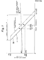
- the required duty ratio at point B is also nearly 55% (to be precise, there is a car speed coefficient of about 0.1%/km/h for the required duty ratio as indicated by chain-line 28, but it may be almost ignored in this example), when the control speed width VB is, for example, 20 km/h, a deviation of occurs, and the car is controlled at 77 km/h at point B.
- Such vehicle cruises at a constant speed as shown in Fig. 2, with the traveling speeds varying with road loads.
- the prior control system of the constant speed cruise control can be roughly represented as shown in Fig. 3 if its non-linear element is disregarded.
- Fig. 4 depicts this control system in terms of its relationships with the target car speed.
- Fig. 6 shows the control system in terms of its relationships with road loads.
- a load U(S) is given at C/S.
- F(S) (the car speed corresponding to the load variation) signalled to the feedback system traces the path illustrated in Fig. 7, and Y(S) varies therewith.
- Such car speed deviation may be rendered to zero when the control criterion is corrected from point A to point C in Fig. 1. However, if the corrected speed is too low, deviation convergence takes much time, while if the corrected speed is too high, stability could be impaired due to excessive correction.
- control speed width VB denotes a range of car speed for varying the output duty ratio D linearly in a range of 0 to 100%, and its inverse number is the gain.
- the set duty ratio SD is the duty ratio corresponding to the target car speed VM, and ideally it is the control center.
- the leading angle control describe above obtains a skip car speed (leading angle car speed) VS by adding the differential value (acceleration) AV of the traveling car speed Vn, in which if Vn changes, VS varies as shown in FIG. 9 , so that the change in Vn may be fed back to the output duty ratio D in advance.
- one of the objects of the invention is to nullify car speed deviation during a constant speed traveling.
- Another object of the invention is to enhance traveling stability.
- Further object of the invention is to prevent hunting right after setting.
- Another object of the invention is to make a car speed change small even if a sudden change of a car speed occurs when a road gradient changes suddenly or the like.
- an automotive cuise control system of duty ratio control type for approximating an actual traveling car speed to a stored target car speed, by on/off control of a control valve of an actuator to adjust the throttle valve opening degree by an output duty ratio D obtained from a control line having a specified gradient showing a conversion characteristic of car speed and duty ratio, in which the set duty ratio SD corresponding to the target car speed is calculated as and the output duty ratio D is calculated as
- the dynamic gain may be increased by the movement of element DM, and the element SD1 is moved while suppressing the car speed deviation, so that the car speed deviation may be nullified while arresting the car speed variations.
- the elements DM and SD1 are claculated as
- the gain of the entire control system becomes high in the low speed traveling region where the vehicle gain is high, accordingly hunting is likely to occur, while in the high speed traveling region where the vehicle gain is low, the gain of the entire control system is low, accordingly the response becomes inferior.
- This may be avoided by varying the gain of the entire control system, but in the generally employed method of varying the static control gain, the stability is impaired.
- the gain of the entire control system is changed by varying the dynamic control gain derived from the response.
- the controller further changes over the value of n depending on the traveling car speed, and corrects to integrate the set duty ratio SD in a direction of approximating the output duty ratio D.
- the controller changes over the value of K , depending on the traveling car speed, and integrates and corrects the set duty ratio SD in a direction of approximating the output duty ratio D.
- the controller furthermore, quickly changes DM and SD1 when the car speed acceleration AVn exceeds a certain value in correction formula where A, B: constants in the unit of dury ratio(%)/ acceleration and integrates and corrects the set duty ratio SD in a direction of approaching the output duty ratio D.
- the duty ratio is calculated mainly at the intermediate point of an integrating element 1 (DM) responding quickly to duty ratio change and an integrating element 2 (SDl) responding slowly to duty ratio change, and it is intended to respond by a quick movement of integrating element against road surface fluctuations or other variations, but if the change of DM is too quick in an ordinary traveling state, the gain becomes too large, which may affect car speed hunting, so that too fast movement is not allowed. Accordingly, where a quick response against sudden changes are required, the control is delayed in this state, and the overshoot or undershoot of car speed may be too large.
- ⁇ Vn exceeds a certain value
- a value proportional to the acceleration is subtracted from each integrating element to give a quick response against a sudden change, thereby preventing delay of control.
- a ⁇ Vn is subtracted from DM
- B ⁇ VN in subtracted from SDl
- A, B are constants in the unit of duty ratio(%)/acceleration.
- the dynamic gain is increased by the movement of element DM, and the element SD1 is moved while suppressing the car speed deviation, so that it is possible to nullify the car speed deviation while controlling the variations of car speed. If the acceleration exceeds a certain value, the values of DM, SD1 are changed in proportion to the acceleration, so that a car speed deviation can be held small even if the road gradient changes suddenly, so that a stable control may be ensured.
- the controller determines a difference AD between the integrating element SD1 or the set duty ratio SD and the output duty ratio D, changing ⁇ corresponding to the magnitude of the difference ⁇ D, and correcting to integrate the integrating element SDl in a direction of approximating the output duty ratio D.
- the integrating element SD1 is changed within a range between an upper limit value and a lower limit value.
- the integrating element DM is changed within a range between an upper limit value and a lower limit value.
- the value of S is limited to a certain value so that the integrating speed may be moderate. By varying this value in various car speed regions, the speed is optimized considering the difference in the vehicle gain.
- This invention in a constant speed cruise control system of duty ratio control type for approximating an actual traveling car speed to a stored target car speed by on/off control of a control valve on an actuator for adjusting the opening degree of throttle valve by an output duty ratio D obtained from a control line of a specified gradient showing the conversion characteristic of car speed and duty ratio, comprises a controller which integrates and corrects a set duty ratio SD in a direction of approximating an output duty ratio D, by determining the difference AD between a set duty ratio SD corresponding to a desired target car speed and an output duty ratio D, and moving the control line parallel at an integrating speed corresponding to the magnitude of this ⁇ D.
- the set duty ratio SD is not fixed, when it is corrected, it is possible to run constantly at a target car speed by theoretically nullifying the car speed deviation. At this time, when the correcting speed is varied depending on the magnitude of difference AD between output duty ratio D and set duty ratio SD,'the car speed deviation may be quickly eliminated in a range not to spoil the stability.
- the integrating speed is limited by fixing Y at a certain value for a specified time after setting the target car speed.
- the value y is selected for differentiated values in car speed regions.
- This invention is a constant speed cruise system of duty ratio control type for approximating an actual traveling car speed to a stored target car speed by on/off control of a control valve of an actuator for adjusting the opening degree of throttle valve by an output duty ratio D obtained from a control line of a specified gradient showing the conversion characteristic of car speed and duty ratio, comprises a controller which integrates and corrects a set duty ratio SD in a direction of approximating an output duty ratio D, by determining the difference ⁇ D between a set duty ratio SD corresponding to the target car speed and the output duty ratio D, and moving parallel the control line at an integrating speed corresponding to the magnitude of this AD within a specified limit range.
- the set duty ratio SD is not fixed, and by correcting it, it is possible to run constantly at a target car speed by theoretically nullifying the car speed deviation.
- the correcting speed is varied depending on the magnitude of the difference 4D between the output duty ratio D and set duty ratio SD
- the car speed deviation may be quickly eliminated in a range not to sacrifice the stability.
- the set duty ratio SD decreases, and at this time, a large car speed overshoot occurs due to the delay of ECU and delay of actuator line.
- the relation is reverse, but a large car speed undershoot occurs according to the same principle.
- the range of integrating correction is limited.
- This invention discloses a leading angle control method of the constant speed traveling control system of duty ratio control type for approximating an actual traveling car speed close to a stored target car speed, by determining the acceleration by differentiating the traveling car speed obtained from car speed signal, calculating the leading angle car speed by adding the acceleration to the traveling car speed, and on/off controlling the control valve of an actuator for adjusting the opening degree of throttle valve by the output duty ratio obtained from the conversion characteristic between the leading angle car speed and duty ratio, in which if the acceleration exceeds a certain value, a correction duty ratio increasing in proportion to the acceleration is added to the output duty ratio.
- the specified value is not zero.
- the specified value is zero.
- FIG. 10 is a system block diagram showing an example of a constant speed traveling control system following the aspect of this invention, in which a controller or ECU 6 (electronic control unit) detects the traveling car speed by the signal from a car speed sensor 6 having a reed switch 4 which is turned on or off by a magnet 2 rotating in proportion to the rotation of the vehicle drive shaft.
- the ECU 6 stored the traveling car speed when a preset switch 8 is turned on, and, after it is turned off, contorls the duty ratio of a control valve 10 of an actuator ACT.
- a pressure is lowered when the control valve 10 is turned on to increase the pressure generating by a diaphragm l2 linked to a throttle valve SL.
- a microcomputer is used in the ECU, and processing in this unit is shown in a block diagram in FIG. 11.
- the output duty ratio D for on/off control of the control valve is determined by the difference between the target car speed VM stored in the memory and the traveling car speed Vn, but precisely it is not Vn itself, but a skip car speed VS is used, which is its sum with the car speed change component (differential component) in a differentiation circuit 22 added up in an adder 24. This is intended to compensate for the loss time due to lag of action of actuator ACT or hysteresis or play in the throttle valve SL or drive system, in a leading direction. Therefore, the skip car speed VS is obtained in the following equation.
- this set duty ratio SD is variable, and can be expressed as:
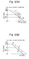
- DM is a high-speed integrating element which will quickly respond to changes in duty ratio (which can also be called as changes in car speed), thereby reducting the set deviation. It operates on the principle that as illustrated in Fig. 12 (a), the control line is made to rotate at high speeds so that the deviation is decreased.
- SD1 is a low-speed integrating element which will respond slowly to changes in duty ratio and decrease the set deviation. Its operation strategy is to shift the control line parallel in the direction of decreasing the deviation as indicated in Fig. 12 (b).
- the figure (a) is an illustration of the operations when there is a drop in the speed of a cap moving from a level to a uphill road (the duty ratio increased), while the figure (d) illustrates the operation including a downhill.
- duty ratio D varies with varying car speeds
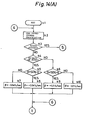
- FIG. 14 is a flow chart showing an embodiment of this invention, and it corresponds to the block diagram in FIG. 18.
- a high speed integrating element DM is changed in proportion to the difference from the duty ratio D. That is, at step s16, supposing when the present element DM(i) is changed by a from the previous DM (i-1) , if this a is, for example, the difference between the present duty ratio D(i) and the previous-element DM(i- l ) is applied, and the correcting speed is varied (where K is a constant).
- a low speed integrating element SD1 is, using a variable a which is smaller than a, expressed, at step s37, as follows and when this ⁇ is a fixed value, the correcting speed is constant. For example, it is assumed:
- a duty ratio D(i) is output, by which the actuator is controlled, so that constant speed cruising is effected at duty ratio D(i).
- the calculation cycle at steps s2 to s49 is, for example, 50 msec/1 cycle.
- step S23 duty ratio deviation ⁇ D is determined by a difference between a set duty ratio SD (its initial value is SD 0 ) and output duty ratio Dand depending on the size of this ⁇ D, ⁇ is determined so that SD is corrected at step s24 to s36.
- control diagram is moved parallel from the solid line (including points A, B) to the broken line (including point C), and thereafter the car speed at car speed deviation of zero around point C.
- the setting method is based on the following three basic rules. [1] No correction is made where the ⁇ D is very small (for example, ⁇ 1%). This is a kind of dead zone, and it is intended to keep stable by not making unnecessary correction while traveling stably. [2] The correction speed is faster when the absolute value of ⁇ D is greater. That is, when the ⁇ D is great (the car speed deviation is large), the correction speed is raised to decrease the car speed deviation as quickly as possible, and when the car speed deviation becomes small, the correction speed is lowered to prevent excessive correction.
- the correction speed is varied between the increasing direction and the decreasing direction. For example, when the ⁇ D is over 20%, the correction speed (the SD decreasing direction) is extremely enlarged to decrease car speed overshoot when changing from upslope to downslope, thereby keeping the speed increase state to a minimum.
- discriminating by the difference AD of duty ratio as in this embodiment is same as discriminating by the magnitude of car speed deviation, but to be more precise it is different from the point that the output duty ratio D is discriminated by the sum of the skip car speed VS and control speed width VB (which is a value to express the gain of ECU, electronic control unit), and as compared with the method of discriminating merely by the magnitude of car speed deviation, it is excellent in two points, that is: (I) a transient control amount is taken into consideration, and ( II ) it is discriminated by a duty ratio which directly influences the actual actuator line operation.
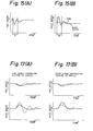
- FIG. 15 is a diagram to explain the operation of this invention.
- variations of other factors accompanying the duty ratio change may be arrested, so that hunting as shown in FIG. 8 may be prevented.
- ⁇ D may be defined not by SD-D, but by SD1-D.
- SD1 is calculated based on the equation (1) at step s37.
- the dynamic control gain changes as shown in FIG. 21, so that the gain of the entire control system can be.changed along with the variation of the vehicle gain.
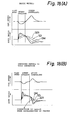
- FIG. 17 is an operational waveform diagram, in which the broken line denotes the characteristic omitting steps sll to sl5 in FIG. 14, and the solid line represents the characteristic with steps all to sl5 in F I G. 19.
- the processing performs quick changing DM and SD1 to make car speed change small when car speed acceleration is large, for example when passing from upslope to downslope. That is if the acceleration ⁇ Vn exceeds, for example, 1.25 km/h/sec, 4 ⁇ Vn is subtracted from DM at step s18, and ⁇ Vn from SD1 at s38. As a result, both DM and SD1 change suddenly. However, since the AVn takes the plus sign when accelerating, and the minus sign when decelerating, when the duty is lowered, both DM and SD1 decrease, when it is raised, both values increase.
- FIG. 18 explains this operation. More specifically, FIG.18 (A) shows the basic system of FIG. 14, that is, the constitution without steps sl7, s18; s38, s39, while FIG.18 (B) relates to an improved method including steps s17, s18; s38, s39.
- the duty ratio change in FIG. 18 ( B ) is steeper than in FIG.18 (A) , which means that the car speed change may be suppressed to a small extent if the road surface gradiemt changes suddenly.
- processings at steps sl9 to s22 and steps s40 to s43 are performed after the processing at steps s17, s18; s38, s39.
- Both (1) and (2) may be established by the one-side limit only.
- the one-side limit only.
- the value of DM is limited by use of an upper and lower limit values Al and Bl.
- the value of SD1 is limited by use of an upper and lower limit values C and E which can be obtained in a same manner.
- the value of n is a value for use at step s47 to calculate SD.
- n 1
- the control line in FIG. 12 (A) stand upright, and the gain becomes maximum.
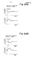
- FIG. 19 is a operational waveform diagram, in which the broken line denotes the characteristic omitting steps s44 to s46 in FIG. 14, and the solid line represents the characteristic with steps s44 to s46 in FIG.14.
- step s47 set duty ratio SD is calculated, next, at step s48, output duty ratio D being calculated.
- a control signal corresponding to the duty ratio D is output to the actuator at step s49.
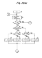
- FIG. 20 shows a different embodiment of this invention inwhich the set duty ratio SD is corrected directly by ⁇ at steps s24 to s36 of FIG. 14 without using DM and SD1.
- Steps sl to s10 in FIG. 14 correspond to steps 1l to l10
- stpes l3a, l3b, l21 to l31 correspond to steps n23. to n36.
- the value ⁇ in FIG. 14 is rewritten as y in FIG. 20.
- This value of SD is cotrolled in a range between upper limit A2 and lower limit B2 at steps l12 to l15. As this ⁇ D increases, the value of y is set larger.
- SDi may be corrected as shown in equation (53a).
- the other constitution is same as in the preceding embodiments.
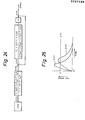
- the improved control system of the constant speed cruise control is roughly as depicted in Fig. 21 if its non-linear element is disregarded.
- Fig. 22 is an illustration of this control system in relation to the target car speed.
- Fig. 24 describes the relationships between the control system and road load.
- F IG. 26 is another embodiment according to the invention, and this invention presents a constant speed cruise control system comprising an output duty ratio calculating means 101 for calculating the output duty ratio D corresponding to the difference between a detected traveling car speed and a preset car speed based on the control car speed width for calculation of output duty ratio calculation and a set duty ratio, and a driving means 103 for driving a coil 102a for control valve in an actuator 102 for driving a throttle valve operating on a driving source of engine negative pressure by generating a pulse signal possessing a duty ratio corresponding to an output duty ratio calculated in this output duty ratio calculating means 101, in which are also contained an average calculating means 104 to determine the average of output duty ratios calculated by the output duty ratio calculating means 101, and a set duty ratio correcting means 105 for obtaining a set duty ratio for calculation of output duty ratio of output duty ratio calculating means 101 by correcting a set duty ratio (fixed value) predetermined according to the average of output duty ratios calculated by the average calculating means 104.
- the predetermined set duty ratio is improper, the actual car speed contains the target car speed and stationary deviation, but at this time, a difference depending on the stationary deviation occurs between the average of output duty ratios and the set duty ratio, and the set%duty ratio to be applied to the output duty ratio calculating means 101 is corrected in a direction to decrease the stationary deviation by the set duty ratio correcting means 105, so that the stationary deviation is controlled small.
- the set duty ratio for calculation of output duty ratio is corrected by the output duty ratio calculating means in a direction to decrease the stationary deviation by the set duty ratio correcting means, so that the stationary deviation may be reduced, and moreover since it is not necessary to vary the control speed width, the stability is not sacrificed.
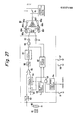
- FIG. 27 is a block diagram of essential parts showing concretely the system of FIG. 26.
- numeral 80 is a reed switch for detection of traveling speed of an automobile
- 81 is a permanent magnet which is rotated being driven by a speed meter cable.
- the reed switch 80 is turned on and off by the rotation of the permanent magnet 81, and generates a pulse signal having a frequency proportional to the car speed.
- This pulse signal is applied to a frequency-voltage converter (F/V converter) 82 to be converted into a DC voltage possessing a level proportional to the car speed.
- the output voltage of the F/V converter 82 is held in a memory circuit 84 when an analog switch 82 is turned on.
- the set voltage held in the memory circuit 84 is fed into a differential amplifier 85, where the difference from the output voltage from the F/V converter 82, that is, the traveling car speed is obtained.
- This difference signal is converted into a digital value in an A/D converter 86, and is fed into the input port of microcomputer 87.
- the microcomputer 87 is to generate a pulse signal possessing an output duty ratio depending on the difference signal, and the pulse signal, while an AND circuit 96 is opened, passes through this AND circuit 96 and is applied to a control valve coil 89i of an actuator 89 through an amplifier 90.
- the actuator 89 comprises a control valve 89a and a release valve 89b, and the control valve 89a is opened or closed by the control valve coil 89i which is excited by the output of the amplifier 90. Then, as the control valve coil 89i is energized, the atmospheric pressure from port 89c is cut off, and an intake pipe negative pressure from port 89d is led into a chamber 89e, and when the energization is cut off, the negative pressure from the port 89d is cut off, and the atmospheric pressure from the port 89c is led into the chamber 89e.
- the release valve 89b is opened and closed by a release valve coil 89j which is driven by the output of a self-holding circuit 92 through an amplifier 91, and when energized, it cuts off the atmospheric pressure from port 89f, and when energization is turned off, it introduces this atmospheric pressure into the chamber 89e.
- a diaphragm 89g moves, so that a rod 89h which is linked to an accelerator link (not shown) is moved in the axial direction, thereby controlling the opening degree of a throttle valve SL.
- the high speed limit circuit 94 is designed to close the AND circuit 95 when receiving a chime signal telling that the speed has exceeded, for example, 100 km/h, so as to prevent the storing operation of set car speed.
- a cancellation switch 98 is a switch to reset the self-holding circuit 92, and when reset, the self-holding circuit 92 stops energization through the amplifier 91.
- a resume switch 97 is intended to resume the constant speed traveling control once interrupted by the cancellation switch 98, and when it is pressed, constant speed traveling control is effected on the basis of the previous set car speed as the target.
- a low speed limit circuit 99 is intended to force to reset the self-holding circuit 92 when the car speed drops below, for example, 30 km/h.
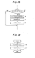
- FIG. 28 is a flow chart showing an example of calculation and output processing of output duty ratio executed by the microcomputer 87
- FIG. 29 is a flow chart showing an example of averating processing of output duty ratio executed by the micorcomputer87, of which operation is described below.
- FIG. 26 is a block diagram of microcomputer 87.
- the microcomputer executes steps S2 to S4 for calculation of duty ratio shown in FIG. 28 in a specified period, for example, at every 50 msec (Sl).
- steps S2 to S4 for calculation of duty ratio shown in FIG. 28 in a specified period, for example, at every 50 msec (Sl).
- the steps s2 to s3 correspond to the output duty ratio calculating means 101.
- the microcomputer 87 after calculating the present output duty ratio D at step S3, delivers a pulse signal possessing a duty ratio equal to that duty ratio to the AND circuit 96 through output port (S4).
- the microcomputer 87 by executing the processing shown in FIG. 29 at every, for example, 50 msec, is always correcting the set duty ratio SD used in calculation of output duty ratio. That is, every time the correction period comes around, the mean Dmean of a new output duty ratio is calculated in the following equation from the mean Dmean of the previous output duty ratio and the output duty ratio D at that time (S10).
- M is an averaging coefficient (a normalizing coefficient), and is, for example, 7.
- This step s10 corresponds to the mean calculation means 104 in FIG 26.
- the microcomputer 87 calculates the mean Dmean of output duty ratio, and also claculates the set duty ratio SD for calculating a new output duty ratio in the following equation (24) (Sll).
- SD 0 is a value determined in the designing state, corresponding to the conventional set duty ratio, and is a fixed value preliminarily stored in the read only memory of microcomputer 87.
- K is a constant for substantially determining the variable width of set duty ratio SD for calculation of output duty ratio, and it is set at, for example, about 2.
- This step s 11 corresponds to the set duty ratio correcting means 105 in FIG. 26.
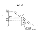
- the set duty ratio SD for calculation of output duty ratio is corrected on the basis of mean Dmean of output duty ratio in every specified period as shown above, if, for example as shown in FIG. 30, there is a speed deviation of ⁇ XN in the control by the initial fixed set duty ratio SD O , the output duty ratio D is corrected toward the D mean depending on the difference between SD O and the mean Dmean of output duty ratio at that time, and the characteristic curve of car speed difference to output duty ratio is revised, for example, from the solid line to the virtual line shown in the same diagram, so that the stationary deviation is decreased as ⁇ XNl.
- FIG. 31 is a block diagram showing a calculation part of leading angle car speed, in which numeral 150 is a car speed signal processing part, 152 is a preset switch, 153 is a set car speed memory unit, 154 is an output processing part, 155 is an actuator, 156 is a primary differentiator, and 157 is a secondary differentiator.
- the input car speed f(t) is differentiated in the differentiator 156, and is multiplied by a coefficient Kl in a coefficient multiplier 160, while it is further differentiated in the differentiator 157 and multiplied by another coefficient K2 in a coefficient multiplier 162. Therefore, the leading angle car speed g(t) obtained by adding them up in an adder 158 is as follows.
- the third term of the right side of the above equation is the portion not found in the conventional system, and it is part B shown in FIG. 32 (A). This part B is effective to cancel and nullify the overcompensating part A due to the second term of the right side of the above equation.
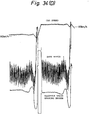
- FIG. 34 (A) The operational waveform diagram of this case is shown in FIG. 34 (A), in which the car speed is increased from 40 km/h at 5 km/h increments at high gain.
- the absolute quantity of hunting is small, and the difference is converged in a short time.
- the moving average of the high order differential term may be taken. That is, the leading angle car speed calculation in the microcomputer is performed as
- K2 0 in a high speed region over it.
- FIG. 34 (B) refers to a case of constant speed traveling in a high speed region with the value of K2 in equation ( 25 ) being fixed. If there is disturbance in the car speed signal in such a case, the duty ratio changes significantly. The change of this duty ratio is larger than in the conventional case shown in FIG. 34 (C), which indicates the shortcoming of adding a secondary differential term. However, when K2 is set smaller in high speed region, the effect of the secondary differential term is lowered, and the variation width of duty ratio becomes narrow as shown in FIG. 34 (D), so that the stability of control is maintained.
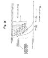
- Fig. 35 is a schematic drawing showing how the car speed sensing portion works, wherein A of the following equation 29 and m of the equation 30 are both set at 4 and the time synchronizing timing at 50 msec.
- the processing operation in this preferred embodiment is done by the processing circuit 188 in Fig. 10.
- the pulse cycle Ti * can be determined from the step rl to r9 in the flowchart in Fig. 36.
- Each pulse of car speed signals is used as an interruption signal.
- the process is interrupted (at step rl) every time the rise of an edge of the car speed signal pulse is sensed, and the interruption time is read and the time data previously read and stored are shifted one by one (step r2, r3, r4, r5 and r6).
- step rl which is comprised of a central processing unit (CPU), a timer connected to the CPU through a bus line, a random access memory (RAM), a read only memory (ROM) and other devices, reads the interruption time into the CPU register in response to the clock pulse from the timer each time interruption conditions are set out (at step rl).
- the last fith to preceding time data (interruption time) stored in each address from N+ 4th to Nth in the RAM is rotated one after another; the time data most recently picked up is stored in the Nth address as the latest time, thereby performing processes r2 through r6.
- the pulse cycle Ti is calculated (step 7) by deducting the last fifth time data registered in the N + 4th address of RAM from the last one stored in the Nth address.
- This filtered pulse synchronization value Ti is determined and updated at each rising of a car speed pulse signal, maintaining the latest pulse cycle filtered value Ti in a specified address of RAM.
- this interruption process is put to an end and the main process is resumed (step r9).
- the cor speed filtered value Xn * is determined using the step PI and P2 in the flowchart of Fig. 37.
- This process indicates detailed car speed calculation strategies (step S2), performed each 5 msec.
- the car speed Xn is calculated (step Pl) by reading out the latest pulse cycle filtered value Ti * from a given address of RAM, and applying an appropriate coefficient to an inverse number of the Ti * .
- a primary integrating filter is cited as an example, but this filtered value calculation is applicable to a secondary or other filters.
- pulse cycle Ti in a give number (4 in this embodiment) is determined by synchronizing with each pulse of pulse signals from a car speed sensor 6, the value is filtered by the equation 22 to calculate pulse cycle filtered value Ti * , which is converted at each specified interval into an invert number to determine car speed Xn. Then, the value is filtered with the equation 30 to determine car speed filtered value Xn * and introduced as cruising car speed Vn. Accordingly, disturbance of pulse signals caused by the car speed sensor 6, and also traveling car speeds with less low-frequency modulation can be obtained. For this reason, the traveling car speed Vn is always a true representation of actual car speeds, thereby leading to improved driving stability.
- the pulse cycle calculation procedure in which pulse-to-pulse cycle Ti in synchronism with pulse is also a traveling distance interval synchronization measurement.
- time cycle measurement is carried out at a specified interval to give car speed Xn. Consequently, in the pulse cycle and time synchronization measurements, a modulation waveform and a modulation frequency differ with regard to the same input, thus giving no constant modulation operation.
- appropriate integrating filters are provided to give traveling car speed Vn showing less modulation characteristics.
- Fig. 38 is a block diagram showing the processing strategies of other embodiments of this invention.
- the car speed signal from the car speed sensor is deprived of noise by passing the same through a car speed filter 184 according to the previously described method, giving a car speed Vn.
- a set switch 8 is a switch used to set a target car speed VM.
- the set switch 8 is turned on to read a car speed Vn at that time into a memory 190.
- the throttle valve is controlled depending on the difference between the target car speed VM and the car speed Vn.
- the skipped car speed VS where a derivative component ⁇ V processing the car speed Vn with a derivation means 192 is added to the car speed VM, is employed.
- the difference signal between the target car speed VM and the skipped car speed VS (VM - VS) is provided to a duty conversion means 194 used to determine the duty for controlling said actuator.
- Said derivative component AV from the derivation means 192 is given also to a determination means 168 and a correction means 170. Using the correction means 170, corrected values Kl and K2 are determined according to the derivative component AV or vehicle acceleration.
- the derivative component ⁇ V or vehicle acceleration is higher than a specified value (during acceleration conditions) or lower (during deceleration conditions)
- a swtich 172 is thrown on, to give the corrected values Kl and K2 to a duty ratio conversion means 194.
- the duty ratio conversion means 194 is also provided with a control gain VB for duty ratio control and determines a duty ratio D.
- Fig. 39 is a graph shwoing the operation of this preferred embodiment.
- the control using the conventional system is as indicated by (G).
- G For instance, in combined use with an automatic transmission, when a vehicle is moving from a level to a uphill road, the duty ratio increases with decreasing speed, but if a small gear ratio is selected, the car speed decreases due to lack of tractive force. When the difference between the target and actual car speeds reaches the specified value, the gear is shifted down. When this occurs, the traction increases and the car accelerates, but at the time of the shiftdown occuring the duty ratio has become considerably large, and it takes time to reduce the duty ratio to the required value. Hence, the car speed shoots over.
- the control delay is compensated to prevent overshoot by applying a large correction duty ratio temporarily.
- Fig. 40 shows an embodiment of the microprocessor-based processing scheme of that indicated in Fig. 38.
- a duty ratio D is determined by the following formula:
- Steps ql to ql7 are steps designed to determine a correction duty ratio FU during deceleration, in contrast with the steps q4 to q10.
- Steps q13 and ql4 are given to set an upper confine y2 on the correction duty ratio FU, and in this embodiment, the limit y2 is set at 10%.
- the decrease in the correction duty ratio FU should be as quick as in the case of the correction duty ratio FD.
- Steps ql6 and q17 are designed to set a lower limit on the correction duty ratio FU, thereby preventing the correction duty ratio FU from dropping below 0 or making an inverse correction.
- Step ql8 is a step used to determine a skipped car speed VS, performing operations of a car speed Vn and its derivative component AV.
- a duty ratio D is determined from the aforestated various values in accordance with the equation.
- a duty ratio 20 is put out, and is used to control the actuator (step q21).
- the forgoing process consists of determining an output duty ratio D by the following equation, and of varying correction duty ratios FD and FU as follows with the calculation cycle of a microprocessor as a unit of change:
- the cases 1 and 3 above refer to the time of compensation, and the cases 2 and 4 represent the resetting time.
- the resetting constants ⁇ 2 and ⁇ 4, and the limiting constants yl and y2 are constant, while the compensation terms K1 ⁇ V and K2 ⁇ V are variables including an acceleration ⁇ V (Kl and K2 are constants), and are used to change FD and FU in proportion to an acceleration ⁇ V.
- correction duty ratios for acceleration and deceleration are separately processed depending on their characteristics to permit more accurate control.
- Fig. 41 is another example of the other microprocessor-based processing schemes.
- a duty ratio D is determined by:
- this processing procedure consists of computing an output duty ratio from the following equation, and of changing a correction duty ratio F in accordance with an acceleration AV in the following manner:
- a control scheme is simple enough to achieve with a short program, thus allowing curtailed memory capacity.
- Fig. 42 shows another example of the microprocessor-based processing strategies.
- a duty ratio D is determined by:
- wl to w4, w5 to ⁇ 11, and ⁇ 13 to w21 are not mentioned here since they are identical to ql to q4, q5 to qll and ql3 to q21 in Fi g . 40.
- Difference between this embodiment and that in Fig. 40 lies in the fact that in the latter correction duty ratios FD and FU are increased or decreased in response to acceleration, while inthis embodiment they are increased or decreased with time.
- the forgoing process consists of determining an output duty ratio D by the following equation, and of changing correction duty ratios FD and FU as follows in proportion to time. Supposing the calculation cycle of a microprocessor to be a unit of change:
- the cases 1 and 3 above refer to the time of compensation, and the cases 2 and 4 represent the resetting time.
- the increasing and decreasing constants ⁇ 1 to ⁇ 4 and the limiting constants yl and y2 are constant, and resetting is rapidly performed with ⁇ 1 ⁇ ⁇ 2 and ⁇ 3 ⁇ ⁇ 4.
- yl 20%
- y2 10%.
- correction duty ratios FU and FD there is no need to determine correction duty ratios FU and FD in proportion to car speeds, thereby achieving a shorter program and smaller memory capacity.
- Different correction duty ratios FD and FU are applied during acceleration and deceleration conditions, and thus control can be maintained so that it suits their respective characteristics.
- the correction amount of a correction duty ratio F can be kept constant, i.e., F ⁇ F + ⁇ 1 at step U5 and F ⁇ F + ⁇ 2 at step U8.
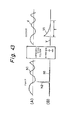
- This invention further relates to a car speed signal processing circuit of a constant speed traveling device for integrating and processing a car speed signal from the car speed sensor, and using its output in the setting of target car speed and detection of traveling car speed, in which setting is prohibited for a specified time when a car speed change exceeding a specified value occurs in the car speed signal.
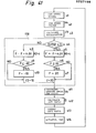
- FIG. 44 is a flow chart showing a processing thereof, in which the calculation cycle is 50 msec.
- the car speed filter 184 shown in FIG. 38 is the integrating filter, and advancing from step zl to z3, the difference VR O - VR1 of two momentary values of the integrated output is compared with a specified value, and abnormal portion N2 in FIG. 43 is detected.
- VR O is the present calculated value
- VR1 is the previous calculated value.
- the car speed filter 184 may be placed somewhere between the buffer 186 and processing circuit 188 in FIG. 10.
- the criterion is the acceleration of 1 km/h per 50 msec, therefore, 20 km/h/sec (generally, the limit is about 4 km/h/sec). If a speed change exceeding this standard is detected, the prohibit timer in the processing circuit 188 is set at step z6 to prohibit control in this period, and the prohibition is canceled at steps z7, z9. It means that, if the preset switch 8 in FIG. 10 or FIG. 38 is pressed, data is not stored in the memory 190 or processing circuit 188 (that is, it is cleared). This prohibition of control continues until the prohibit timer expires (for example, 3 seconds), and thereafter the prohibit timer is cleared, and the control mode is set at step z8.
Landscapes
- Engineering & Computer Science (AREA)
- Physics & Mathematics (AREA)
- Fluid Mechanics (AREA)
- Chemical & Material Sciences (AREA)
- Combustion & Propulsion (AREA)
- Transportation (AREA)
- Mechanical Engineering (AREA)
- Controls For Constant Speed Travelling (AREA)
Applications Claiming Priority (24)
| Application Number | Priority Date | Filing Date | Title |
|---|---|---|---|
| JP294229/85 | 1985-12-26 | ||
| JP294224/85 | 1985-12-26 | ||
| JP29422585A JPS62152924A (ja) | 1985-12-26 | 1985-12-26 | 定速走行装置の車速信号処理回路 |
| JP29422985A JPS62168721A (ja) | 1985-12-26 | 1985-12-26 | 車速信号処理方法 |
| JP29422785A JPS62168727A (ja) | 1985-12-26 | 1985-12-26 | デユ−テイ制御型の定速走行制御装置 |
| JP294225/85 | 1985-12-26 | ||
| JP294227/85 | 1985-12-26 | ||
| JP294228/85 | 1985-12-26 | ||
| JP29422885A JPS62168728A (ja) | 1985-12-26 | 1985-12-26 | デユ−テイ制御型の定速走行制御装置 |
| JP29422685A JPS62168726A (ja) | 1985-12-26 | 1985-12-26 | デユ−テイ制御型の定速走行制御装置 |
| JP29422485A JPS62168720A (ja) | 1985-12-26 | 1985-12-26 | デユ−テイ制御型の定速走行制御装置 |
| JP294226/85 | 1985-12-26 | ||
| JP298132/85 | 1985-12-27 | ||
| JP298130/85 | 1985-12-27 | ||
| JP29813285A JPS62168732A (ja) | 1985-12-27 | 1985-12-27 | デユ−テイ制御型の定速走行制御装置 |
| JP29813085A JPS62168730A (ja) | 1985-12-27 | 1985-12-27 | デユ−テイ制御型定速走行制御装置の進角制御方法 |
| JP298125/85 | 1985-12-27 | ||
| JP29813185A JPS62168731A (ja) | 1985-12-27 | 1985-12-27 | デユ−テイ制御型定速走行制御装置の進角制御方法 |
| JP298131/85 | 1985-12-27 | ||
| JP29812585A JPS62168729A (ja) | 1985-12-27 | 1985-12-27 | デユ−テイ制御型の定速走行制御装置 |
| JP298849/85 | 1985-12-28 | ||
| JP29884985A JPS62168734A (ja) | 1985-12-28 | 1985-12-28 | デユ−テイ制御型の定速走行制御装置 |
| JP61085491A JPH069942B2 (ja) | 1986-04-14 | 1986-04-14 | 定速走行装置の進角制御方式 |
| JP85491/86 | 1986-04-14 |
Publications (3)
| Publication Number | Publication Date |
|---|---|
| EP0227198A2 true EP0227198A2 (de) | 1987-07-01 |
| EP0227198A3 EP0227198A3 (en) | 1988-07-20 |
| EP0227198B1 EP0227198B1 (de) | 1991-03-27 |
Family
ID=27583388
Family Applications (1)
| Application Number | Title | Priority Date | Filing Date |
|---|---|---|---|
| EP86202379A Expired EP0227198B1 (de) | 1985-12-26 | 1986-12-24 | System zur Geschwindigkeitsregelung durch Einstellung der Solleistung und ein Verfahren zur Regulierung mit Phasenvoreilung |
Country Status (4)
| Country | Link |
|---|---|
| US (1) | US4870583A (de) |
| EP (1) | EP0227198B1 (de) |
| CA (1) | CA1292301C (de) |
| DE (1) | DE3678408D1 (de) |
Families Citing this family (14)
| Publication number | Priority date | Publication date | Assignee | Title |
|---|---|---|---|---|
| JPS6485842A (en) * | 1987-09-29 | 1989-03-30 | Aisin Seiki | Control device for constant speed travelling |
| JP2634668B2 (ja) * | 1989-05-30 | 1997-07-30 | 日産自動車株式会社 | 車速自動制御装置 |
| US5189618A (en) * | 1989-06-28 | 1993-02-23 | Nippondenso Co., Ltd. | Automotive cruise control system for controlling vehicle to run at constant speed |
| US5235512A (en) * | 1991-06-24 | 1993-08-10 | Ford Motor Company | Self-tuning speed control for a vehicle |
| JPH07501291A (ja) * | 1991-08-09 | 1995-02-09 | フォード モーター カンパニー | 速度誤差に関する可変利得を有する速度制御システム |
| US5260876A (en) * | 1991-08-09 | 1993-11-09 | Ford Motor Company | Speed control system with adaptive gain control during a speed alteration |
| JPH06144077A (ja) * | 1992-11-11 | 1994-05-24 | Jidosha Denki Kogyo Co Ltd | 自動定速走行装置の制御方法 |
| US5483448A (en) * | 1992-12-14 | 1996-01-09 | Ford Motor Company | Adaptive vehicle suspension system with mechanism for varying controller gains in response to changing road roughness conditions |
| JP3746245B2 (ja) * | 2002-04-11 | 2006-02-15 | 株式会社日立製作所 | 定速走行制御装置 |
| DE10251563A1 (de) * | 2002-11-06 | 2004-05-19 | Robert Bosch Gmbh | Verfahren zur Regelung der Geschwindigkeit eines Fahrzeugs |
| JP2006027457A (ja) * | 2004-07-16 | 2006-02-02 | Nissan Motor Co Ltd | 車両用走行制御装置 |
| JP4297866B2 (ja) * | 2004-11-09 | 2009-07-15 | 株式会社日立製作所 | 可変動弁機構の診断機能の評価方法及び可変動弁機構の診断装置 |
| SE535422C2 (sv) * | 2010-06-23 | 2012-07-31 | Scania Cv Ab | Metod och modul för att styra ett fordons hastighet |
| EP2794328A4 (de) | 2011-12-22 | 2016-09-14 | Scania Cv Ab | Verfahren und modul zur steuerung der geschwindigkeit eines fahrzeuges basierend auf regeln und/oder kosten |
Family Cites Families (13)
| Publication number | Priority date | Publication date | Assignee | Title |
|---|---|---|---|---|
| NL214582A (de) * | 1956-02-20 | |||
| US3893537A (en) * | 1970-07-03 | 1975-07-08 | Aisin Seiki | Apparatus for control of a vehicle constant speed mechanism |
| US3767972A (en) * | 1972-03-21 | 1973-10-23 | Ass Eng Ltd | Speed responsive systems |
| FR2409385A1 (fr) * | 1977-11-16 | 1979-06-15 | Renault | Procede de regulation de vitesse d'un moteur a combustible interne et systeme limiteur en faisant application |
| JPH0114500Y2 (de) * | 1980-03-28 | 1989-04-27 | ||
| JPS5755417A (en) * | 1980-09-18 | 1982-04-02 | Toyota Motor Corp | Constant speed running control method |
| US4419729A (en) * | 1980-10-27 | 1983-12-06 | The Bendix Corporation | Automatic speed control for heavy vehicles |
| US4374422A (en) * | 1980-10-27 | 1983-02-15 | The Bendix Corporation | Automatic speed control for heavy vehicles |
| JPS5779227A (en) * | 1980-11-05 | 1982-05-18 | Toyota Motor Corp | Constant speed travelling apparatus for vehicle |
| US4463822A (en) * | 1981-05-27 | 1984-08-07 | Fujitsu Ten Limited | Cruise control system for automotive vehicle |
| US4598370A (en) * | 1983-01-27 | 1986-07-01 | Honda Giken Kogyo Kabushiki Kaisha | Apparatus for control of acceleration and deceleration during auto-cruise |
| JPS59203850A (ja) * | 1983-05-04 | 1984-11-19 | Diesel Kiki Co Ltd | エンジンの回転速度制御装置 |
| JPS6056639A (ja) * | 1983-09-09 | 1985-04-02 | Aisin Seiki Co Ltd | 定速走行装置 |
-
1986
- 1986-12-24 CA CA000526319A patent/CA1292301C/en not_active Expired
- 1986-12-24 EP EP86202379A patent/EP0227198B1/de not_active Expired
- 1986-12-24 DE DE8686202379T patent/DE3678408D1/de not_active Expired - Lifetime
- 1986-12-29 US US06/948,134 patent/US4870583A/en not_active Expired - Lifetime
Also Published As
| Publication number | Publication date |
|---|---|
| CA1292301C (en) | 1991-11-19 |
| EP0227198B1 (de) | 1991-03-27 |
| US4870583A (en) | 1989-09-26 |
| DE3678408D1 (de) | 1991-05-02 |
| EP0227198A3 (en) | 1988-07-20 |
Similar Documents
| Publication | Publication Date | Title |
|---|---|---|
| EP0982172B1 (de) | Abstandsbezogenes Fahrgeschwindigkeitsregelsystem für Kraftfahrzeuge | |
| US5758306A (en) | Vehicle cruise control system | |
| US5333058A (en) | Yaw motion control device | |
| EP0227198B1 (de) | System zur Geschwindigkeitsregelung durch Einstellung der Solleistung und ein Verfahren zur Regulierung mit Phasenvoreilung | |
| EP0612641B1 (de) | Methode und Vorrichtung zur Fahrgeschwindigkeits-Steuerung | |
| EP1053903B1 (de) | Abstandsbezogenes Fahrgeschwindigkeitsregelsystem | |
| US5099941A (en) | Cruise control device for motor vehicles | |
| US4621705A (en) | System for automatically controlling vehicle speed | |
| US6175799B1 (en) | Apparatus and method for automatically controlling vehicular velocity | |
| US6529814B2 (en) | System and method for controlling vehicle velocity and inter-vehicle distance | |
| EP1061495B1 (de) | Vorrichtung und Verfahren zur Geschwindigkeits-und-Abstandsreglung eines Fahrzeugs | |
| US5749063A (en) | Automatic vehicle speed controlling apparatus | |
| US5047941A (en) | Wheel acceleration slip control device | |
| GB2279765A (en) | Vehicle movement stability control | |
| EP0467353B1 (de) | Geschwindigkeitsregelvorrichtung für Kraftfahrzeuge | |
| JPH11291789A (ja) | 車両用走行制御装置 | |
| JP3528319B2 (ja) | 車両用定速走行装置 | |
| JP3591015B2 (ja) | 車両用定速走行制御装置 | |
| JP3901020B2 (ja) | 車間距離制御装置 | |
| JP3235435B2 (ja) | 車速制御装置 | |
| JPH0790719B2 (ja) | 車両速度制御装置 | |
| JP3555237B2 (ja) | 車両用定速走行制御装置 | |
| JPH1035322A (ja) | 車両用自動車速制御装置 | |
| JP2871169B2 (ja) | 車両用定速走行装置 | |
| JPH08295152A (ja) | 車両用定速走行制御装置 |
Legal Events
| Date | Code | Title | Description |
|---|---|---|---|
| PUAI | Public reference made under article 153(3) epc to a published international application that has entered the european phase |
Free format text: ORIGINAL CODE: 0009012 |
|
| AK | Designated contracting states |
Kind code of ref document: A2 Designated state(s): DE FR GB |
|
| PUAL | Search report despatched |
Free format text: ORIGINAL CODE: 0009013 |
|
| AK | Designated contracting states |
Kind code of ref document: A3 Designated state(s): DE FR GB |
|
| 17P | Request for examination filed |
Effective date: 19890110 |
|
| 17Q | First examination report despatched |
Effective date: 19890605 |
|
| GRAA | (expected) grant |
Free format text: ORIGINAL CODE: 0009210 |
|
| AK | Designated contracting states |
Kind code of ref document: B1 Designated state(s): DE FR GB |
|
| REF | Corresponds to: |
Ref document number: 3678408 Country of ref document: DE Date of ref document: 19910502 |
|
| ET | Fr: translation filed | ||
| PLBE | No opposition filed within time limit |
Free format text: ORIGINAL CODE: 0009261 |
|
| STAA | Information on the status of an ep patent application or granted ep patent |
Free format text: STATUS: NO OPPOSITION FILED WITHIN TIME LIMIT |
|
| 26N | No opposition filed | ||
| REG | Reference to a national code |
Ref country code: GB Ref legal event code: 746 Effective date: 19991203 |
|
| REG | Reference to a national code |
Ref country code: FR Ref legal event code: D6 |
|
| REG | Reference to a national code |
Ref country code: GB Ref legal event code: IF02 |
|
| PGFP | Annual fee paid to national office [announced via postgrant information from national office to epo] |
Ref country code: FR Payment date: 20051208 Year of fee payment: 20 |
|
| PGFP | Annual fee paid to national office [announced via postgrant information from national office to epo] |
Ref country code: GB Payment date: 20051221 Year of fee payment: 20 |
|
| PGFP | Annual fee paid to national office [announced via postgrant information from national office to epo] |
Ref country code: DE Payment date: 20051222 Year of fee payment: 20 |
|
| PG25 | Lapsed in a contracting state [announced via postgrant information from national office to epo] |
Ref country code: GB Free format text: LAPSE BECAUSE OF EXPIRATION OF PROTECTION Effective date: 20061223 |
|
| REG | Reference to a national code |
Ref country code: GB Ref legal event code: PE20 |