EP0227212A1 - Automatischer Überschwemmungs-Kontrollapparat für eine Rohrleitung - Google Patents
Automatischer Überschwemmungs-Kontrollapparat für eine Rohrleitung Download PDFInfo
- Publication number
- EP0227212A1 EP0227212A1 EP19860306990 EP86306990A EP0227212A1 EP 0227212 A1 EP0227212 A1 EP 0227212A1 EP 19860306990 EP19860306990 EP 19860306990 EP 86306990 A EP86306990 A EP 86306990A EP 0227212 A1 EP0227212 A1 EP 0227212A1
- Authority
- EP
- European Patent Office
- Prior art keywords
- ball
- flow
- flow channel
- fluid
- outlet port
- Prior art date
- Legal status (The legal status is an assumption and is not a legal conclusion. Google has not performed a legal analysis and makes no representation as to the accuracy of the status listed.)
- Granted
Links
- 239000012530 fluid Substances 0.000 claims description 10
- 230000002159 abnormal effect Effects 0.000 claims description 7
- 229920001971 elastomer Polymers 0.000 claims description 3
- 239000005060 rubber Substances 0.000 claims description 3
- 239000000463 material Substances 0.000 claims description 2
- 238000007789 sealing Methods 0.000 abstract 1
- 239000007789 gas Substances 0.000 description 32
- VNWKTOKETHGBQD-UHFFFAOYSA-N methane Chemical compound C VNWKTOKETHGBQD-UHFFFAOYSA-N 0.000 description 16
- 239000003345 natural gas Substances 0.000 description 8
- ATUOYWHBWRKTHZ-UHFFFAOYSA-N Propane Chemical compound CCC ATUOYWHBWRKTHZ-UHFFFAOYSA-N 0.000 description 4
- 238000005260 corrosion Methods 0.000 description 2
- 230000007797 corrosion Effects 0.000 description 2
- 239000001294 propane Substances 0.000 description 2
- 230000006835 compression Effects 0.000 description 1
- 238000007906 compression Methods 0.000 description 1
- 230000000881 depressing effect Effects 0.000 description 1
- 239000007788 liquid Substances 0.000 description 1
- 238000000034 method Methods 0.000 description 1
- 229920003052 natural elastomer Polymers 0.000 description 1
- 229920001194 natural rubber Polymers 0.000 description 1
- 210000002445 nipple Anatomy 0.000 description 1
- 239000004033 plastic Substances 0.000 description 1
- 229920003023 plastic Polymers 0.000 description 1
- 229910001220 stainless steel Inorganic materials 0.000 description 1
- 239000010935 stainless steel Substances 0.000 description 1
- 229920003051 synthetic elastomer Polymers 0.000 description 1
- 239000005061 synthetic rubber Substances 0.000 description 1
Images
Classifications
-
- F—MECHANICAL ENGINEERING; LIGHTING; HEATING; WEAPONS; BLASTING
- F16—ENGINEERING ELEMENTS AND UNITS; GENERAL MEASURES FOR PRODUCING AND MAINTAINING EFFECTIVE FUNCTIONING OF MACHINES OR INSTALLATIONS; THERMAL INSULATION IN GENERAL
- F16K—VALVES; TAPS; COCKS; ACTUATING-FLOATS; DEVICES FOR VENTING OR AERATING
- F16K17/00—Safety valves; Equalising valves, e.g. pressure relief valves
- F16K17/20—Excess-flow valves
- F16K17/34—Excess-flow valves in which the flow-energy of the flowing medium actuates the closing mechanism
-
- Y—GENERAL TAGGING OF NEW TECHNOLOGICAL DEVELOPMENTS; GENERAL TAGGING OF CROSS-SECTIONAL TECHNOLOGIES SPANNING OVER SEVERAL SECTIONS OF THE IPC; TECHNICAL SUBJECTS COVERED BY FORMER USPC CROSS-REFERENCE ART COLLECTIONS [XRACs] AND DIGESTS
- Y10—TECHNICAL SUBJECTS COVERED BY FORMER USPC
- Y10T—TECHNICAL SUBJECTS COVERED BY FORMER US CLASSIFICATION
- Y10T137/00—Fluid handling
- Y10T137/7722—Line condition change responsive valves
- Y10T137/7723—Safety cut-off requiring reset
- Y10T137/7726—Responsive to change in rate of flow
- Y10T137/7727—Excessive flow cut-off
-
- Y—GENERAL TAGGING OF NEW TECHNOLOGICAL DEVELOPMENTS; GENERAL TAGGING OF CROSS-SECTIONAL TECHNOLOGIES SPANNING OVER SEVERAL SECTIONS OF THE IPC; TECHNICAL SUBJECTS COVERED BY FORMER USPC CROSS-REFERENCE ART COLLECTIONS [XRACs] AND DIGESTS
- Y10—TECHNICAL SUBJECTS COVERED BY FORMER USPC
- Y10T—TECHNICAL SUBJECTS COVERED BY FORMER US CLASSIFICATION
- Y10T137/00—Fluid handling
- Y10T137/7722—Line condition change responsive valves
- Y10T137/7837—Direct response valves [i.e., check valve type]
- Y10T137/7869—Biased open
- Y10T137/7871—Weight biased
- Y10T137/7873—Ball valves
-
- Y—GENERAL TAGGING OF NEW TECHNOLOGICAL DEVELOPMENTS; GENERAL TAGGING OF CROSS-SECTIONAL TECHNOLOGIES SPANNING OVER SEVERAL SECTIONS OF THE IPC; TECHNICAL SUBJECTS COVERED BY FORMER USPC CROSS-REFERENCE ART COLLECTIONS [XRACs] AND DIGESTS
- Y10—TECHNICAL SUBJECTS COVERED BY FORMER USPC
- Y10T—TECHNICAL SUBJECTS COVERED BY FORMER US CLASSIFICATION
- Y10T137/00—Fluid handling
- Y10T137/7722—Line condition change responsive valves
- Y10T137/7837—Direct response valves [i.e., check valve type]
- Y10T137/7904—Reciprocating valves
- Y10T137/7908—Weight biased
- Y10T137/7909—Valve body is the weight
- Y10T137/791—Ball valves
Definitions
- This invention relates to an automatic overflow control apparatus or safety valve suitable for a pipeline which operates to shut off the flow of fluid in the pipeline when it reaches an excessive rate. It is suitable for use in connections between a main supply line and a subsidiary user system, particularly between a gas supply main and a domestic gas system.
- the object of this invention is to provide an automatic overflow control apparatus which will automatically shut off a pipeline in the event of an unusually high rate of fluid flow developing in it, e.g. in the event of a leak in the supply conduit due to breakage, corrosion or other occurence.
- the present invention provides an automatic overflow control apparatus comprising a housing having an inlet port for connection to a supply of fluid, an outlet port, a flow channel between the two ports, and a ball freely disposed in the flow channel, the diameter of the ball in relation to that of the flow channel being such that normal flow of fluid can pass through the flow channel around the ball but an abnormal flow of fluid will urge the ball towards the outlet port, the inner face of the outlet port being provided with a flexible annular ring in which the ball can seat when urged to the outlet port by the abnormal flow, the ball when seated in the ring forming a seal to shut off the abnormal flow.
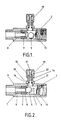
- FIGs 1 and 2 there is illustrated an apparatus for automatically shutting off the flow channel therein when unusually high gas flows occur.
- This apparatus may be inserted between a main gas supply line and a domestic system.
- a ball 5 which is of a diameter smaller than the internal diameter of the flow channel 4, the gap between the ball and the inner wall of the flow channel being sufficient to permit normal flows of gas past the ball without undue drop of pressure.
- the ball is preferably of stainless steel.
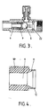
- Near the outlet port 3 is a hollow cylindrical bushing 6, the axis of which is aligned with that of the flow channel. Its rearward end (i.e. the end nearest the outlet port 3 of the housing) is a frictional tight fit within the rebate 7 in the flow channel. Its forward end is rebated to provide an annular gap between that end of the bushing and the inner wall of the flow passage at which position there is a further rebate 8 in the inner wall. In the space between rebates 7 and 8 is located in gas tight manner, one end of a valve seating 9.
- the valve seating 9 is of a hollow cylindrical shape.
- One end 10 is of internal and external diameters suitable for fitting onto the bushing to provide the gas tight seal between the bushing and the flow channel.
- the other end 11 is tapered outwardly at its inner surface and rebated in its outer surface to provide a thin annular lip 12.
- the annular lip 12 is of smaller diameter than that of the ball 5.
- the valve seating (9) may be of natural or synthetic rubber or of resilient plastics material.
- Inserted in the inlet port 2 of the housing 1 is a wire coil 13 which serves to retain the ball 5 within the flow channel 4 without significantly impeding the gas flow.
- the ball 5 When the ball 5 is positioned in the annular lip 12 to close the flow channel it may be dislodged from the lip by depressing the cap 19 whereupon the head of the transversely arranged piston contacts the ball and knocks it down to its normal free position in the flow channel.
- the ball-retaining coil 13 is replaced by an orifice plate 22.
- the orifice in the plate which orifice is of smaller diameter than that of the ball 5, is offset from the center of the plate and is aligned with the ball 5 when it is freely positioned on the lower part of the flow channel.
Landscapes
- Engineering & Computer Science (AREA)
- General Engineering & Computer Science (AREA)
- Mechanical Engineering (AREA)
- Safety Valves (AREA)
- Pipeline Systems (AREA)
- Taps Or Cocks (AREA)
Priority Applications (1)
| Application Number | Priority Date | Filing Date | Title |
|---|---|---|---|
| AT86306990T ATE53442T1 (de) | 1985-09-11 | 1986-09-10 | Automatischer ueberschwemmungs-kontrollapparat fuer eine rohrleitung. |
Applications Claiming Priority (2)
| Application Number | Priority Date | Filing Date | Title |
|---|---|---|---|
| US06/775,025 US4638835A (en) | 1985-09-11 | 1985-09-11 | Automatic overflow control apparatus for the pipeline passage |
| US775025 | 2001-02-01 |
Publications (2)
| Publication Number | Publication Date |
|---|---|
| EP0227212A1 true EP0227212A1 (de) | 1987-07-01 |
| EP0227212B1 EP0227212B1 (de) | 1990-06-06 |
Family
ID=25103094
Family Applications (1)
| Application Number | Title | Priority Date | Filing Date |
|---|---|---|---|
| EP19860306990 Expired - Lifetime EP0227212B1 (de) | 1985-09-11 | 1986-09-10 | Automatischer Überschwemmungs-Kontrollapparat für eine Rohrleitung |
Country Status (4)
| Country | Link |
|---|---|
| US (1) | US4638835A (de) |
| EP (1) | EP0227212B1 (de) |
| AT (1) | ATE53442T1 (de) |
| DE (1) | DE3671791D1 (de) |
Families Citing this family (14)
| Publication number | Priority date | Publication date | Assignee | Title |
|---|---|---|---|---|
| US4830046A (en) * | 1988-04-22 | 1989-05-16 | Hose Specialties/Capri, Inc. | Excess flow control valve |
| USD336861S (en) | 1990-04-25 | 1993-06-29 | Michael Nicholas | Moisture detector for a water control unit |
| US5772116A (en) | 1993-12-02 | 1998-06-30 | Holt; Earl R. | Recirculating paint system having an improved spray gun |
| FR2754872B1 (fr) * | 1996-10-21 | 1998-12-24 | Briffault Sa | Conduit constitue de deux troncons susceptibles de se deplacer l'un par rapport a l'autre et rearmant une securite interne |
| US6199584B1 (en) | 1997-12-23 | 2001-03-13 | Whetstone Group International, Inc. | Fluid flow control valve |
| US6260575B1 (en) | 1997-12-23 | 2001-07-17 | Whetstone Group International, Inc. | Fluid flow control valve |
| US6263911B1 (en) | 1997-12-23 | 2001-07-24 | Whetstone Group International, Inc. | Fluid flow control valve |
| US7033133B2 (en) * | 2003-12-10 | 2006-04-25 | Honeywell International, Inc. | Air turbine starter having a low differential check valve |
| US7033134B2 (en) * | 2004-02-24 | 2006-04-25 | Honeywell International, Inc. | Air turbine starter having a force balanced, pressure energized, weighted check valve |
| US7014419B2 (en) * | 2004-02-27 | 2006-03-21 | Honeywell International, Inc. | Passive improved air turbine starter lubrication system |
| DE102013203530A1 (de) | 2013-03-01 | 2014-09-04 | Magna Mirrors Holding Gmbh | Rückspiegelanordnung für Kraftfahrzeuge |
| WO2017120888A1 (zh) * | 2016-01-15 | 2017-07-20 | 白翼志 | 流体遮断安全装置 |
| US10850295B2 (en) * | 2017-08-15 | 2020-12-01 | Hunter Industries, Inc. | Sprinkler with flow guard feature |
| CN109114434A (zh) * | 2018-09-03 | 2019-01-01 | 蒋晓武 | 一种具有紧急切断的燃气管道检漏报警装置 |
Citations (4)
| Publication number | Priority date | Publication date | Assignee | Title |
|---|---|---|---|---|
| US2942618A (en) * | 1958-08-21 | 1960-06-28 | Sun Oil Co | High-low automatic shut-off valve |
| FR1371834A (fr) * | 1963-06-18 | 1964-09-11 | Vallourec | Robinet pour canalisations de fluides |
| US3191277A (en) * | 1961-05-17 | 1965-06-29 | Clarence O Glasgow | Valve seat |
| DE2843152A1 (de) * | 1978-09-05 | 1980-03-13 | Peter Ing Grad Ginzler | Vorrichtung zur sperrung bzw. freigabe des durchflusses eines fliessfaehigen mediums |
Family Cites Families (8)
| Publication number | Priority date | Publication date | Assignee | Title |
|---|---|---|---|---|
| US1078347A (en) * | 1911-03-06 | 1913-11-11 | Cyrus A Haas | Valve-stem and check-valve therefor. |
| US1100219A (en) * | 1913-06-11 | 1914-06-16 | Charles Butters | Apparatus for filtering slimes. |
| US2916042A (en) * | 1955-09-26 | 1959-12-08 | Jr Francis E Brady | Float ball check valve |
| US3407827A (en) * | 1963-09-20 | 1968-10-29 | John L. Follett | Automatic shut-off valve |
| US3322145A (en) * | 1964-11-02 | 1967-05-30 | Autotrol Corp | Adjustable constant flow valve |
| US3977430A (en) * | 1974-08-22 | 1976-08-31 | Bushee Joseph J | Ball check valve construction with pressure-responsive reset means |
| US4030520A (en) * | 1976-08-05 | 1977-06-21 | Sands Asa D | Ball-type safety valve |
| US4257448A (en) * | 1978-12-15 | 1981-03-24 | Shiu Chan K | Flow cut-off device for insertion in a gas duct |
-
1985
- 1985-09-11 US US06/775,025 patent/US4638835A/en not_active Expired - Lifetime
-
1986
- 1986-09-10 EP EP19860306990 patent/EP0227212B1/de not_active Expired - Lifetime
- 1986-09-10 DE DE8686306990T patent/DE3671791D1/de not_active Expired - Lifetime
- 1986-09-10 AT AT86306990T patent/ATE53442T1/de not_active IP Right Cessation
Patent Citations (4)
| Publication number | Priority date | Publication date | Assignee | Title |
|---|---|---|---|---|
| US2942618A (en) * | 1958-08-21 | 1960-06-28 | Sun Oil Co | High-low automatic shut-off valve |
| US3191277A (en) * | 1961-05-17 | 1965-06-29 | Clarence O Glasgow | Valve seat |
| FR1371834A (fr) * | 1963-06-18 | 1964-09-11 | Vallourec | Robinet pour canalisations de fluides |
| DE2843152A1 (de) * | 1978-09-05 | 1980-03-13 | Peter Ing Grad Ginzler | Vorrichtung zur sperrung bzw. freigabe des durchflusses eines fliessfaehigen mediums |
Also Published As
| Publication number | Publication date |
|---|---|
| EP0227212B1 (de) | 1990-06-06 |
| ATE53442T1 (de) | 1990-06-15 |
| DE3671791D1 (de) | 1990-07-12 |
| US4638835A (en) | 1987-01-27 |
Similar Documents
| Publication | Publication Date | Title |
|---|---|---|
| EP0227212B1 (de) | Automatischer Überschwemmungs-Kontrollapparat für eine Rohrleitung | |
| US4088436A (en) | Gas distribution system | |
| FI82130B (fi) | Foerdelningsventil. | |
| CA2141621C (en) | Vacuum breaker for faucets | |
| US4458719A (en) | Quick coupler service fitting | |
| US5743291A (en) | Sanitary safety device | |
| CN201333925Y (zh) | 加注管嘴定位装置以及燃料加注管嘴对中设备 | |
| US4287912A (en) | Monoflow ball valve and system | |
| AU604973B2 (en) | Integral metal seal for hydraulic coupling | |
| US4921004A (en) | Piercing surge regulator valve and apparatus | |
| US7059340B2 (en) | Valve assembly for pipe disconnectors | |
| US5465751A (en) | Excess flow valve | |
| US4271992A (en) | Tap for dispensing beverages | |
| US7681584B2 (en) | Pipe disconnector | |
| US3545473A (en) | Combined blending and changeover valve for fluids | |
| EP0292486A1 (de) | Selbsttätiges absperrventil für flüssigkeiten. | |
| EP1179699B1 (de) | Elektromagnetisches Ablaufventil für Druckluftanlagen | |
| US5492305A (en) | Connector assembly for connecting a source of fluid with a container to be filled | |
| US5971003A (en) | Apparatus to service gas meters | |
| GB2263748A (en) | Pipe block | |
| ATE225485T1 (de) | Ventil für zentralschmieranlage | |
| US2954245A (en) | Dispensing device | |
| US6523568B1 (en) | Combination air vent/probe port and method of constructing same | |
| CN220622864U (zh) | 调压阀 | |
| GB2174779A (en) | Pipe couplings |
Legal Events
| Date | Code | Title | Description |
|---|---|---|---|
| PUAI | Public reference made under article 153(3) epc to a published international application that has entered the european phase |
Free format text: ORIGINAL CODE: 0009012 |
|
| 17P | Request for examination filed |
Effective date: 19860930 |
|
| AK | Designated contracting states |
Kind code of ref document: A1 Designated state(s): AT BE CH DE FR GB IT LI NL SE |
|
| 17Q | First examination report despatched |
Effective date: 19880812 |
|
| GRAA | (expected) grant |
Free format text: ORIGINAL CODE: 0009210 |
|
| AK | Designated contracting states |
Kind code of ref document: B1 Designated state(s): AT BE CH DE FR GB IT LI NL SE |
|
| REF | Corresponds to: |
Ref document number: 53442 Country of ref document: AT Date of ref document: 19900615 Kind code of ref document: T |
|
| REF | Corresponds to: |
Ref document number: 3671791 Country of ref document: DE Date of ref document: 19900712 |
|
| ITF | It: translation for a ep patent filed | ||
| ET | Fr: translation filed | ||
| PGFP | Annual fee paid to national office [announced via postgrant information from national office to epo] |
Ref country code: SE Payment date: 19900913 Year of fee payment: 5 |
|
| PGFP | Annual fee paid to national office [announced via postgrant information from national office to epo] |
Ref country code: CH Payment date: 19900918 Year of fee payment: 5 |
|
| PGFP | Annual fee paid to national office [announced via postgrant information from national office to epo] |
Ref country code: AT Payment date: 19900919 Year of fee payment: 5 |
|
| PGFP | Annual fee paid to national office [announced via postgrant information from national office to epo] |
Ref country code: BE Payment date: 19900925 Year of fee payment: 5 |
|
| PGFP | Annual fee paid to national office [announced via postgrant information from national office to epo] |
Ref country code: NL Payment date: 19900930 Year of fee payment: 5 |
|
| PLBE | No opposition filed within time limit |
Free format text: ORIGINAL CODE: 0009261 |
|
| STAA | Information on the status of an ep patent application or granted ep patent |
Free format text: STATUS: NO OPPOSITION FILED WITHIN TIME LIMIT |
|
| 26N | No opposition filed | ||
| PG25 | Lapsed in a contracting state [announced via postgrant information from national office to epo] |
Ref country code: AT Effective date: 19910910 |
|
| PG25 | Lapsed in a contracting state [announced via postgrant information from national office to epo] |
Ref country code: SE Effective date: 19910911 |
|
| ITTA | It: last paid annual fee | ||
| PG25 | Lapsed in a contracting state [announced via postgrant information from national office to epo] |
Ref country code: LI Effective date: 19910930 Ref country code: CH Effective date: 19910930 Ref country code: BE Effective date: 19910930 |
|
| BERE | Be: lapsed |
Owner name: CHUANG RONG-CHAO Effective date: 19910930 |
|
| PG25 | Lapsed in a contracting state [announced via postgrant information from national office to epo] |
Ref country code: NL Effective date: 19920401 |
|
| NLV4 | Nl: lapsed or anulled due to non-payment of the annual fee | ||
| REG | Reference to a national code |
Ref country code: CH Ref legal event code: PL |
|
| PGFP | Annual fee paid to national office [announced via postgrant information from national office to epo] |
Ref country code: FR Payment date: 19920909 Year of fee payment: 7 |
|
| PGFP | Annual fee paid to national office [announced via postgrant information from national office to epo] |
Ref country code: DE Payment date: 19920923 Year of fee payment: 7 |
|
| PG25 | Lapsed in a contracting state [announced via postgrant information from national office to epo] |
Ref country code: FR Free format text: LAPSE BECAUSE OF NON-PAYMENT OF DUE FEES Effective date: 19940531 |
|
| PG25 | Lapsed in a contracting state [announced via postgrant information from national office to epo] |
Ref country code: DE Effective date: 19940601 |
|
| REG | Reference to a national code |
Ref country code: FR Ref legal event code: ST |
|
| EUG | Se: european patent has lapsed |
Ref document number: 86306990.2 Effective date: 19920408 |
|
| REG | Reference to a national code |
Ref country code: GB Ref legal event code: IF02 |
|
| PGFP | Annual fee paid to national office [announced via postgrant information from national office to epo] |
Ref country code: GB Payment date: 20020823 Year of fee payment: 17 |
|
| PG25 | Lapsed in a contracting state [announced via postgrant information from national office to epo] |
Ref country code: GB Free format text: LAPSE BECAUSE OF NON-PAYMENT OF DUE FEES Effective date: 20030910 |
|
| GBPC | Gb: european patent ceased through non-payment of renewal fee |
Effective date: 20030910 |
|
| PG25 | Lapsed in a contracting state [announced via postgrant information from national office to epo] |
Ref country code: IT Free format text: LAPSE BECAUSE OF NON-PAYMENT OF DUE FEES Effective date: 20050910 |