EP0227221A1 - Dispositif d'expansion - Google Patents
Dispositif d'expansion Download PDFInfo
- Publication number
- EP0227221A1 EP0227221A1 EP86307606A EP86307606A EP0227221A1 EP 0227221 A1 EP0227221 A1 EP 0227221A1 EP 86307606 A EP86307606 A EP 86307606A EP 86307606 A EP86307606 A EP 86307606A EP 0227221 A1 EP0227221 A1 EP 0227221A1
- Authority
- EP
- European Patent Office
- Prior art keywords
- sleeve
- expander
- slots
- expander member
- radial
- Prior art date
- Legal status (The legal status is an assumption and is not a legal conclusion. Google has not performed a legal analysis and makes no representation as to the accuracy of the status listed.)
- Granted
Links
Images

Classifications
-
- F—MECHANICAL ENGINEERING; LIGHTING; HEATING; WEAPONS; BLASTING
- F16—ENGINEERING ELEMENTS AND UNITS; GENERAL MEASURES FOR PRODUCING AND MAINTAINING EFFECTIVE FUNCTIONING OF MACHINES OR INSTALLATIONS; THERMAL INSULATION IN GENERAL
- F16B—DEVICES FOR FASTENING OR SECURING CONSTRUCTIONAL ELEMENTS OR MACHINE PARTS TOGETHER, e.g. NAILS, BOLTS, CIRCLIPS, CLAMPS, CLIPS OR WEDGES; JOINTS OR JOINTING
- F16B13/00—Dowels or other devices fastened in walls or the like by inserting them in holes made therein for that purpose
- F16B13/04—Dowels or other devices fastened in walls or the like by inserting them in holes made therein for that purpose with parts gripping in the hole or behind the reverse side of the wall after inserting from the front
- F16B13/06—Dowels or other devices fastened in walls or the like by inserting them in holes made therein for that purpose with parts gripping in the hole or behind the reverse side of the wall after inserting from the front combined with expanding sleeve
- F16B13/063—Dowels or other devices fastened in walls or the like by inserting them in holes made therein for that purpose with parts gripping in the hole or behind the reverse side of the wall after inserting from the front combined with expanding sleeve by the use of an expander
- F16B13/066—Dowels or other devices fastened in walls or the like by inserting them in holes made therein for that purpose with parts gripping in the hole or behind the reverse side of the wall after inserting from the front combined with expanding sleeve by the use of an expander fastened by extracting a separate expander-part, actuated by the screw, nail or the like
-
- B—PERFORMING OPERATIONS; TRANSPORTING
- B60—VEHICLES IN GENERAL
- B60B—VEHICLE WHEELS; CASTORS; AXLES FOR WHEELS OR CASTORS; INCREASING WHEEL ADHESION
- B60B33/00—Castors in general ; Anti-clogging castors
- B60B33/0002—Castors in general ; Anti-clogging castors assembling to the object, e.g. furniture
-
- F—MECHANICAL ENGINEERING; LIGHTING; HEATING; WEAPONS; BLASTING
- F16—ENGINEERING ELEMENTS AND UNITS; GENERAL MEASURES FOR PRODUCING AND MAINTAINING EFFECTIVE FUNCTIONING OF MACHINES OR INSTALLATIONS; THERMAL INSULATION IN GENERAL
- F16B—DEVICES FOR FASTENING OR SECURING CONSTRUCTIONAL ELEMENTS OR MACHINE PARTS TOGETHER, e.g. NAILS, BOLTS, CIRCLIPS, CLAMPS, CLIPS OR WEDGES; JOINTS OR JOINTING
- F16B7/00—Connections of rods or tubes, e.g. of non-circular section, mutually, including resilient connections
- F16B7/02—Connections of rods or tubes, e.g. of non-circular section, mutually, including resilient connections with conical parts
- F16B7/025—Connections of rods or tubes, e.g. of non-circular section, mutually, including resilient connections with conical parts with the expansion of an element inside the tubes due to axial movement towards a wedge or conical element
-
- Y—GENERAL TAGGING OF NEW TECHNOLOGICAL DEVELOPMENTS; GENERAL TAGGING OF CROSS-SECTIONAL TECHNOLOGIES SPANNING OVER SEVERAL SECTIONS OF THE IPC; TECHNICAL SUBJECTS COVERED BY FORMER USPC CROSS-REFERENCE ART COLLECTIONS [XRACs] AND DIGESTS
- Y10—TECHNICAL SUBJECTS COVERED BY FORMER USPC
- Y10S—TECHNICAL SUBJECTS COVERED BY FORMER USPC CROSS-REFERENCE ART COLLECTIONS [XRACs] AND DIGESTS
- Y10S411/00—Expanded, threaded, driven, headed, tool-deformed, or locked-threaded fastener
- Y10S411/904—Fastener or fastener element composed of nonmetallic material
- Y10S411/908—Resinous material
Definitions
- This invention relates to expander devices for anchoring in a hole by expansion therein. It relates particularly not exclusively, to the securing of castors to the legs of furniture and the like.
- an expander device for anchoring a castor in a hole by expansion therein; the device comprising a radially expansible sleeve having a conical inner surface which extends over at least a major portion of the axial extent of the sleeve; an expander member engageable in the sleeve and having an outer surface at least a major portion of which is conical; the conical surface portions of the sleeve and the expander member being adapted for sliding interengagement over a major portion of the axial extent of the sleeve such that axial movement of one of the expander member and the sleeve relative to the other causes radial expansion of the sleeve; an elongate, externally-threaded member engaged in a complementary, axially-extending tapped bore in the expander member; and means for rotating the externally-threaded member relative to the expander member whereby to move the expander member relative to the sleeve and thereby to expand the s
- the externally-threaded member has a multi-start (eg. a three start) thread.
- the conical inner surface portion of the sleeve is preferably formed over at least half, and more preferably at least three quarters, of the axial extent of the sleeve.
- the outer radial extent of the expander member may be less than the outer radial extent of the sleeve. In this way, the sleeve with the expander member in a preliminarily assembled state may be inserted in the hole, even if the hole is of only a slightly greater size than the sleeve in its unexpanded state.
- the moving means act between the expander member and one end of the sleeve.
- the moving means may comprise abutment means for acting against said one end of the sleeve.
- the expandability of the sleeve will be achieved by at least two first slots in the sleeve extending from one end thereof part way towards the opposite end, and at least two second slots extending from the opposite end part way towards the one end.
- a preferred arrangement of the slots is asymmetrical so as to define major and minor sleeve portions therebetween, so that during expansion of the sleeve deformation thereof takes place predominantly in the minor portion or portions.
- the expander member may be provided with a radial protrusion for each second slot, the protrusions being spaced apart angularly to the same extent as are the second slots, each protrusion being adapted to be engaged within a respective one of the second slots within which it is a snap fit and is slidable longitudinally.
- Each protrusion conveniently has a radial face and another face which is oblique to the radial face, the protrusions being arranged in pairs, the radial faces of the protrusions of each pair being the adjacent faces of that pair and being in face to face engagement with the respective side wall of the respective slot within which the respective protrusion is engaged whereby to positively oppose relative rotation between the sleeve and the expander member in either angular sense.
- the protrusions serve to interlock the sleeve and the expander member so that. as well as being kept together, they are placed in the correct axial relationship for entry into a bore of minimum size.
- the invention also encompasses a castor having an expander device as above.
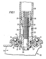
- Figure 1 shows part of a castor 10.
- the castor comprises a fork frame 11 in which at least one castor wheel (not shown) is journalled.
- a hub assembly 12 which includes a double rolling bearing, is provided to allow the usual swivelling of the castor 10 relative to a leg to which it is to be secured.
- the fork frame 11 is formed with an aperture 13 which receives the hub 14 of the hub assembly 12, the two ball races 15 and 16 being seperated by an annular portion 17 of the fork frame 11 in which the aperture 13 is formed, the ball bearings of the two ball races 15 and 16 running on either the upper or lower face of the annular portion 17.
- annular spacer 19 surrounds the hub 14 within the aperture 13 and separates the central portions of the two ball races 15 and 16 which abut it on either its top or its bottom face. It will be appreciated that the longitudinal axis of the castor 10, is upright in use as is shown in Figure 1.
- the hub 14 is formed by a tubular rivet having a shoulder 18 which locates against the upper ball race 15.
- the rivet is passed into a central hole of the upper ball race 15, through the aperture 13 and through a central holes of the annular spacer 19 and the lower ball race 16.
- the lower end of the rivet is then hammered so as to deform outwardly and complete formation of the hub 14, thereby retaining the lower ball race 16 as shown in Figure 1.
- Figures 2 and 3 show that the expander device 20 comprises a radially expansible cylindrical sleeve 21 of a reinforced plastics material such as a glass-filled nylon or a glass-filled polyacetyl material, or other synthetic material.
- the expansibility is achieved by means of longitudinal slots formed in the sleeve 21 together with the inherent flexibility of the plastics material.
- Four of the slots which are referred to from hereon as the first slots 22 and which are spaced circumferentially at 90 degrees with respect to one another, as can be seen from Figure 2, extend from the upper end of the sleeve 21 towards the lower end over a majority of the length of the sleeve 21.
- the slots 23 which are referred to from hereon as the second slots 23 and which are spaced circumferentially at 90 degrees with respect to one another as well, extend from the lower end of the sleeve 21 towards the upper end, again over a majority of the axial extent of the sleeve 21.
- the first and second slots 22 and 23 are arranged asymmetrically with respect to each other so as to define major and minor arcuate sleeve portions 24 and 25 therebetween, the major arcuate sleeve portions 24 each subtending an angle at the axis of the sleeve 21 in the unexpanded state of the sleeve 21 which is about twice that subtended at that axis by each of the minor arcuate sleeve portions 25.
- Figure 1 shows that the inner surface of the sleeve 21 is conical over about three quarters of the length of the sleeve 21.
- the angle of taper is relatively small (viz. about 8 0 to the longitudinal axis) although it could be somewhat greater, say up to about 15°, or slightly smaller, say a little less than 5°.
- An expander member 26 also of a reinforced plastics material, is formed with a correspondingly conical outer surface for sliding engagement with the conical inner surface portion of the sleeve 21.
- the expander member 26 has a threaded central bore to receive a bolt 27 which passes through the bore of the hub 14.
- the bolt 27 is a washer faced bolt having a "washer" portion 28 for engagement with the lower end of the hub 14.
- the washer faced bolt 27 is used because of its reduced head size which will restrict the torque applied during assembly.
- Figure 4 shows, that the bolt 27 has a three-start thread. Hence it has a lead, or advance per revolution, which is three times that of a single start thread having the same pitch.
- use of the three-start thread minimises the risk of over- tightening of the bolt. That is because the mechanical advantage is lower than it would be if a single start thread having the same pitch was used since the angle included between the thread and the axis of the bolt is less for the three-start thread than for a single start thread.
- reinforced plastics material for the sleeve 21 and the expander member 26 avoids undesirable deformation and reduces the tendency for each plastics material to compression set.
- each protrusion 31-34 is engaged in a respective one of the second slots 23.
- the four protrusions 31-34 which are each a snap fit in the respective second slot 23 and which are slidable along that second slot 23, are each tapered radially outwardly, having one radial face and another face which is oblique to the radial face without being tangential to the conical outer surface of the expander member 26.
- the protrusions 31-34 are arranged in two opposed pairs 31 and 32, and 33 and 34.
- the radial faces of the protrusions 31 and 32, 33 and 34 of each pair are the adjacent faces of that pair and they are in face to face engagment with the respective side wall of the respective second slot 23 so as to positively prevent relative rotation between the sleeve 21 and the expander member 26 in either direction.
- expander member 26 Although use of a one piece expander member 26, as shown in the drawings, is preferred for various reasons, the expander member could be made in two similar halves, divided along a diametral plane and connected together by integral hinges at one end, which would allow the use of simpler mould tooling.
- All items in the castor 10, other than the sleeve 21 and expander member 26 are of metallic materials.
- the expansible sleeve need not have a cylindrical exterior as shown in Figures 1 to 5.
- the external surface of the expansible sleeve may have any form that is appropriate having regard to the shape of the hole into which it is to be anchored. For example it may be square as shown in Figure 6.
- the expander devices shown in the drawings eliminate the problems described above because the matched conical parts have a relatively long taper and there is always a very large area of engagement as compared to all earlier products.
- the resultant low radial contact pressure in conjunction with the small included angles virtually eliminates compression set' between the matched conical parts and produces a self locking effect which will hold the two components together even if the bolt is partially loosened.
- the expander device 20 can only be removed after the bolt has been hammered upwards to unlock and separate the two conical surfaces.
- Arranging the outer radial extent of the expander member to be less than that of the sleeve enables insertion of the sleeve and the expander member in a preliminarily assembled state into a hole which is only slightly greater in size than the sleeve in its unexpanded state.
Landscapes
- Engineering & Computer Science (AREA)
- General Engineering & Computer Science (AREA)
- Mechanical Engineering (AREA)
- Dowels (AREA)
- Absorbent Articles And Supports Therefor (AREA)
- External Artificial Organs (AREA)
Priority Applications (1)
| Application Number | Priority Date | Filing Date | Title |
|---|---|---|---|
| AT86307606T ATE58873T1 (de) | 1985-10-03 | 1986-10-02 | Vorrichtung zum spreizen. |
Applications Claiming Priority (2)
| Application Number | Priority Date | Filing Date | Title |
|---|---|---|---|
| GB858524419A GB8524419D0 (en) | 1985-10-03 | 1985-10-03 | Expander device |
| GB8524419 | 1985-10-03 |
Publications (2)
| Publication Number | Publication Date |
|---|---|
| EP0227221A1 true EP0227221A1 (fr) | 1987-07-01 |
| EP0227221B1 EP0227221B1 (fr) | 1990-12-05 |
Family
ID=10586134
Family Applications (1)
| Application Number | Title | Priority Date | Filing Date |
|---|---|---|---|
| EP86307606A Expired - Lifetime EP0227221B1 (fr) | 1985-10-03 | 1986-10-02 | Dispositif d'expansion |
Country Status (7)
| Country | Link |
|---|---|
| US (1) | US4805260A (fr) |
| EP (1) | EP0227221B1 (fr) |
| AT (1) | ATE58873T1 (fr) |
| AU (1) | AU588634B2 (fr) |
| CA (1) | CA1278990C (fr) |
| DE (1) | DE3676061D1 (fr) |
| GB (1) | GB8524419D0 (fr) |
Cited By (7)
| Publication number | Priority date | Publication date | Assignee | Title |
|---|---|---|---|---|
| EP0564889A1 (fr) * | 1992-03-27 | 1993-10-13 | Hewi Heinrich Wilke Gmbh | Dispositif de raccordement, notamment pour une pièce de construction tubulaire |
| GB2274983A (en) * | 1993-01-08 | 1994-08-17 | Colson Castors Uk | Castor |
| EP2194225A3 (fr) * | 2008-12-02 | 2012-04-18 | Hailo-Werk Rudolf Loh GmbH & Co. KG | Rouleaux pour une échelle et assemblage comprenant une échelle et de tels rouleaux |
| CN102493988A (zh) * | 2011-11-23 | 2012-06-13 | 朱明龙 | 本体膨胀紧固栓 |
| CN103075579A (zh) * | 2013-01-15 | 2013-05-01 | 广新海事重工股份有限公司 | 一种减震通舱件 |
| ITMI20112105A1 (it) * | 2011-11-18 | 2013-05-19 | Luigi Perego S R L | Dispositivo di supporto mobile e girevole per strutture ad elevato carico |
| IT202000009526A1 (it) * | 2020-04-30 | 2021-10-30 | Lucio Filippelli | Dispositivo di sicurezza per ponteggio a sbalzo |
Families Citing this family (31)
| Publication number | Priority date | Publication date | Assignee | Title |
|---|---|---|---|---|
| US4969232A (en) * | 1989-08-03 | 1990-11-13 | Everest & Jennings, Inc. | Adjustable caster wheel assembly |
| USD327643S (en) | 1990-01-11 | 1992-07-07 | Babcock Industries Inc. | Caster socket |
| US5052075A (en) * | 1990-01-11 | 1991-10-01 | Babcock Industries Inc. | Apparatus and method for securing a caster to an object having a hole |
| DK0588212T3 (da) * | 1992-09-17 | 1996-12-23 | Fmc Corp | Avanceret afsprængsbeklædningssystem |
| GB2286644B (en) * | 1994-05-20 | 1997-07-23 | Rainer Clover | Concealed connection of assembled elements |
| US5765960A (en) * | 1996-06-14 | 1998-06-16 | Carpin Manufacturing, Inc. | Expansion connector for tubular member |
| GB2323860B (en) * | 1997-02-05 | 2001-05-23 | Sector Exhibiting Systems | Artificial wall structure |
| FR2804075B1 (fr) * | 2000-01-25 | 2002-04-19 | Caddie Atel Reunis | Dispositif de montage pour le montage d'une roue sur un chassis en tube, notamment le chassis d'un chariot, et chariot equipe d'au moins un tel dispositif |
| US7114890B2 (en) * | 2001-02-13 | 2006-10-03 | Valenite Inc. | Cutting tool adjustment device |
| DE10200376B4 (de) * | 2002-01-08 | 2004-02-12 | Fico Triad S.A., Rubi | Befestigungsvorrichtung |
| WO2003105650A1 (fr) * | 2002-06-17 | 2003-12-24 | Feltonmix Limited | Rail de coulissement |
| US6944910B2 (en) * | 2002-07-03 | 2005-09-20 | Sunrise Medical Hhg Inc. | Caster wheel assembly with anti-flutter control |
| US6725501B2 (en) | 2002-07-31 | 2004-04-27 | Fki Industries, Inc. | Caster with universal mount and swivel and wheel lock |
| USD559092S1 (en) | 2002-11-19 | 2008-01-08 | Midway Displays, Inc. | Frame securement unit for a caster wheel |
| US7128494B2 (en) * | 2002-11-19 | 2006-10-31 | Midway Displays, Inc. | Method and apparatus for securing a caster wheel |
| US7065828B2 (en) * | 2003-04-07 | 2006-06-27 | Sorensen Mark C | Caster assembly with drawn kingpin rivet |
| US6810561B1 (en) * | 2003-04-15 | 2004-11-02 | Taiwan Ultra Power Industries Ltd. | On a wheel of a rack |
| US7350269B2 (en) * | 2004-10-12 | 2008-04-01 | Dennis Paul Dominic | Adjustable caster and leveling assembly |
| US8221479B2 (en) * | 2007-01-19 | 2012-07-17 | Pbj, Llc | Orthopedic screw insert |
| US20100212108A1 (en) * | 2009-02-24 | 2010-08-26 | Sung-Wang Yang | Castor Having Reinforced Strength |
| DE102010013445B4 (de) * | 2010-03-30 | 2013-05-02 | Bernhard Gritzbach | Verbindungselement zur Drehmomentübertragung zwischen einer Hohlwelle und einem Nabenelement, insbesondere zum Betätigen einer Druckentlastungsklappe oder Luftregelklappe |
| CN102745018A (zh) * | 2011-04-18 | 2012-10-24 | 阳江市飞轮金属制品有限公司 | 移动平台架脚轮 |
| US8789547B1 (en) * | 2013-03-05 | 2014-07-29 | Yunga Tart Llc | Glide pad for walker |
| GB2514627A (en) * | 2013-06-02 | 2014-12-03 | Wilma Lancaster | Expandable connecting plug for castor wheels |
| US9523381B1 (en) | 2013-11-21 | 2016-12-20 | Carpin Manufacturing, Inc. | Socket assembly |
| US9428008B2 (en) | 2013-11-21 | 2016-08-30 | Carpin Manufacturing, Inc. | Socket assembly |
| US9833063B2 (en) | 2015-12-07 | 2017-12-05 | John Blick | Sturdy lightweight table base and method |
| US11141331B2 (en) | 2017-01-26 | 2021-10-12 | Motion Composites Inc. | Wheelchair caster assembly with anti-flutter feature |
| US10479141B2 (en) * | 2018-02-22 | 2019-11-19 | Monahan Products, LLC | Force finger |
| NO345470B1 (en) * | 2019-07-08 | 2021-02-15 | Bikefinder As | Device for fixing equipment to an end of the inner surface of a tube |
| CN221090372U (zh) * | 2023-12-18 | 2024-06-07 | 温州理念箱包配件有限公司 | 用于维修更换的箱包脚轮及其竖轴 |
Citations (4)
| Publication number | Priority date | Publication date | Assignee | Title |
|---|---|---|---|---|
| FR1596797A (fr) | 1968-06-27 | 1970-06-22 | ||
| DE3131525A1 (de) * | 1981-08-08 | 1983-03-03 | Paul Vom Stein & Co, 5632 Wermelskirchen | Loesbare befestigungsvorrichtung fuer lenkrollen |
| DE3210245A1 (de) * | 1982-03-20 | 1983-09-22 | Haco-Rollen-Vertrieb GmbH & Co KG, 5632 Wermelskirchen | Spreizduebelartige befestigungsvorrichtung, insbesondere fuer lenkrollen |
| EP0145795A1 (fr) | 1983-12-02 | 1985-06-26 | Albert Schulte Söhne GmbH. & Co. | Roue pivotante à support amovible |
Family Cites Families (6)
| Publication number | Priority date | Publication date | Assignee | Title |
|---|---|---|---|---|
| US2100873A (en) * | 1935-12-28 | 1937-11-30 | Russell M Roberts | Dowel structure |
| US2173950A (en) * | 1938-02-14 | 1939-09-26 | Harman R Brown | Lockable caster assembly |
| US2955504A (en) * | 1958-06-06 | 1960-10-11 | Louis B Lovrinch | Plastic bolt anchor having means to permit expansion prior to application of bolt and serrations to prevent relative rotation between the body and the sleeve |
| GB1169799A (en) * | 1967-02-23 | 1969-11-05 | Anton Schnetzler | Improvements in or relating to Clamping Bolt Assemblies |
| US3986626A (en) * | 1975-07-18 | 1976-10-19 | Sunbeam Plastics Corporation | Threaded cap and neck for a liquid container |
| US4180175A (en) * | 1977-02-18 | 1979-12-25 | Maxcap, Inc. | Blow molded plastic bottle and antitamper cap |
-
1985
- 1985-10-03 GB GB858524419A patent/GB8524419D0/en active Pending
-
1986
- 1986-10-02 AT AT86307606T patent/ATE58873T1/de not_active IP Right Cessation
- 1986-10-02 US US06/914,362 patent/US4805260A/en not_active Expired - Fee Related
- 1986-10-02 DE DE8686307606T patent/DE3676061D1/de not_active Expired - Fee Related
- 1986-10-02 EP EP86307606A patent/EP0227221B1/fr not_active Expired - Lifetime
- 1986-10-03 CA CA000519726A patent/CA1278990C/fr not_active Expired - Lifetime
- 1986-10-03 AU AU63490/86A patent/AU588634B2/en not_active Revoked
Patent Citations (4)
| Publication number | Priority date | Publication date | Assignee | Title |
|---|---|---|---|---|
| FR1596797A (fr) | 1968-06-27 | 1970-06-22 | ||
| DE3131525A1 (de) * | 1981-08-08 | 1983-03-03 | Paul Vom Stein & Co, 5632 Wermelskirchen | Loesbare befestigungsvorrichtung fuer lenkrollen |
| DE3210245A1 (de) * | 1982-03-20 | 1983-09-22 | Haco-Rollen-Vertrieb GmbH & Co KG, 5632 Wermelskirchen | Spreizduebelartige befestigungsvorrichtung, insbesondere fuer lenkrollen |
| EP0145795A1 (fr) | 1983-12-02 | 1985-06-26 | Albert Schulte Söhne GmbH. & Co. | Roue pivotante à support amovible |
Cited By (8)
| Publication number | Priority date | Publication date | Assignee | Title |
|---|---|---|---|---|
| EP0564889A1 (fr) * | 1992-03-27 | 1993-10-13 | Hewi Heinrich Wilke Gmbh | Dispositif de raccordement, notamment pour une pièce de construction tubulaire |
| GB2274983A (en) * | 1993-01-08 | 1994-08-17 | Colson Castors Uk | Castor |
| GB2274983B (en) * | 1993-01-08 | 1997-04-02 | Colson Castors Uk | Castors |
| EP2194225A3 (fr) * | 2008-12-02 | 2012-04-18 | Hailo-Werk Rudolf Loh GmbH & Co. KG | Rouleaux pour une échelle et assemblage comprenant une échelle et de tels rouleaux |
| ITMI20112105A1 (it) * | 2011-11-18 | 2013-05-19 | Luigi Perego S R L | Dispositivo di supporto mobile e girevole per strutture ad elevato carico |
| CN102493988A (zh) * | 2011-11-23 | 2012-06-13 | 朱明龙 | 本体膨胀紧固栓 |
| CN103075579A (zh) * | 2013-01-15 | 2013-05-01 | 广新海事重工股份有限公司 | 一种减震通舱件 |
| IT202000009526A1 (it) * | 2020-04-30 | 2021-10-30 | Lucio Filippelli | Dispositivo di sicurezza per ponteggio a sbalzo |
Also Published As
| Publication number | Publication date |
|---|---|
| US4805260A (en) | 1989-02-21 |
| AU588634B2 (en) | 1989-09-21 |
| AU6349086A (en) | 1987-04-09 |
| EP0227221B1 (fr) | 1990-12-05 |
| DE3676061D1 (de) | 1991-01-17 |
| ATE58873T1 (de) | 1990-12-15 |
| CA1278990C (fr) | 1991-01-15 |
| GB8524419D0 (en) | 1985-11-06 |
Similar Documents
| Publication | Publication Date | Title |
|---|---|---|
| EP0227221B1 (fr) | Dispositif d'expansion | |
| AU638227B2 (en) | A plug | |
| US3042094A (en) | Locking screw with expanding means at each end | |
| US4407603A (en) | Friction joint | |
| US3501993A (en) | Setscrew with rotatable plastic end | |
| EP0401182B1 (fr) | Boulon d'ancrage | |
| US4287807A (en) | Pull-to-set anchoring device | |
| US4602902A (en) | Expansion dowel assembly | |
| US3448651A (en) | Expansion bolts | |
| CA2000725C (fr) | Tampon expansible | |
| US7186030B2 (en) | Expandable shaft assembly | |
| US4555199A (en) | Support for endless grinding sleeves | |
| US3750519A (en) | Anchor bolt with expansion sleeve | |
| JPWO2015118702A1 (ja) | 緩み止め機能を備えたボルト | |
| US20090199365A1 (en) | Stepped pin assembly for an axle and method therefor | |
| US4893973A (en) | Expansion dowel with axially extending projections | |
| EP0251016B1 (fr) | Dispositif de montage avec douille de serrage | |
| US1844463A (en) | Bolt | |
| US20200378424A1 (en) | Improvements in Joint Forming Devices | |
| US6679662B2 (en) | Expansible plug | |
| US5156507A (en) | Expansible fastening device | |
| GB2311830A (en) | Expansion bolt with multiple expansion shells | |
| CN111396435A (zh) | 具有螺纹拧紧销的自锁螺纹紧固组件及其的使用 | |
| US6345929B1 (en) | Device for the anchorage of an axle | |
| GB2101061A (en) | Conveyors |
Legal Events
| Date | Code | Title | Description |
|---|---|---|---|
| PUAI | Public reference made under article 153(3) epc to a published international application that has entered the european phase |
Free format text: ORIGINAL CODE: 0009012 |
|
| AK | Designated contracting states |
Kind code of ref document: A1 Designated state(s): AT BE DE FR GB IT NL SE |
|
| 17P | Request for examination filed |
Effective date: 19871203 |
|
| 17Q | First examination report despatched |
Effective date: 19890530 |
|
| GRAA | (expected) grant |
Free format text: ORIGINAL CODE: 0009210 |
|
| AK | Designated contracting states |
Kind code of ref document: B1 Designated state(s): AT BE DE FR GB IT NL SE |
|
| REF | Corresponds to: |
Ref document number: 58873 Country of ref document: AT Date of ref document: 19901215 Kind code of ref document: T |
|
| ITF | It: translation for a ep patent filed | ||
| ET | Fr: translation filed | ||
| REF | Corresponds to: |
Ref document number: 3676061 Country of ref document: DE Date of ref document: 19910117 |
|
| PGFP | Annual fee paid to national office [announced via postgrant information from national office to epo] |
Ref country code: FR Payment date: 19910830 Year of fee payment: 6 |
|
| PGFP | Annual fee paid to national office [announced via postgrant information from national office to epo] |
Ref country code: BE Payment date: 19910911 Year of fee payment: 6 |
|
| PGFP | Annual fee paid to national office [announced via postgrant information from national office to epo] |
Ref country code: GB Payment date: 19910918 Year of fee payment: 6 |
|
| PGFP | Annual fee paid to national office [announced via postgrant information from national office to epo] |
Ref country code: DE Payment date: 19911001 Year of fee payment: 6 |
|
| PLBE | No opposition filed within time limit |
Free format text: ORIGINAL CODE: 0009261 |
|
| STAA | Information on the status of an ep patent application or granted ep patent |
Free format text: STATUS: NO OPPOSITION FILED WITHIN TIME LIMIT |
|
| PGFP | Annual fee paid to national office [announced via postgrant information from national office to epo] |
Ref country code: SE Payment date: 19911014 Year of fee payment: 6 |
|
| ITTA | It: last paid annual fee | ||
| PGFP | Annual fee paid to national office [announced via postgrant information from national office to epo] |
Ref country code: NL Payment date: 19911031 Year of fee payment: 6 Ref country code: AT Payment date: 19911031 Year of fee payment: 6 |
|
| 26N | No opposition filed | ||
| PG25 | Lapsed in a contracting state [announced via postgrant information from national office to epo] |
Ref country code: GB Effective date: 19921002 Ref country code: AT Effective date: 19921002 |
|
| PG25 | Lapsed in a contracting state [announced via postgrant information from national office to epo] |
Ref country code: SE Effective date: 19921003 |
|
| PG25 | Lapsed in a contracting state [announced via postgrant information from national office to epo] |
Ref country code: BE Effective date: 19921031 |
|
| BERE | Be: lapsed |
Owner name: FLEXELLO CASTORS & WHEELS P.L.C. Effective date: 19921031 |
|
| PG25 | Lapsed in a contracting state [announced via postgrant information from national office to epo] |
Ref country code: NL Effective date: 19930501 |
|
| GBPC | Gb: european patent ceased through non-payment of renewal fee |
Effective date: 19921002 |
|
| NLV4 | Nl: lapsed or anulled due to non-payment of the annual fee | ||
| PG25 | Lapsed in a contracting state [announced via postgrant information from national office to epo] |
Ref country code: FR Effective date: 19930630 |
|
| PG25 | Lapsed in a contracting state [announced via postgrant information from national office to epo] |
Ref country code: DE Effective date: 19930701 |
|
| REG | Reference to a national code |
Ref country code: FR Ref legal event code: ST |
|
| EUG | Se: european patent has lapsed |
Ref document number: 86307606.3 Effective date: 19930510 |
|
| PG25 | Lapsed in a contracting state [announced via postgrant information from national office to epo] |
Ref country code: IT Free format text: LAPSE BECAUSE OF NON-PAYMENT OF DUE FEES;WARNING: LAPSES OF ITALIAN PATENTS WITH EFFECTIVE DATE BEFORE 2007 MAY HAVE OCCURRED AT ANY TIME BEFORE 2007. THE CORRECT EFFECTIVE DATE MAY BE DIFFERENT FROM THE ONE RECORDED. Effective date: 20051002 |