EP0227256B1 - Hebebock kombiniert mit einer Druckluftpumpe und angetrieben von einem gemeinsamen Motor - Google Patents
Hebebock kombiniert mit einer Druckluftpumpe und angetrieben von einem gemeinsamen Motor Download PDFInfo
- Publication number
- EP0227256B1 EP0227256B1 EP86308292A EP86308292A EP0227256B1 EP 0227256 B1 EP0227256 B1 EP 0227256B1 EP 86308292 A EP86308292 A EP 86308292A EP 86308292 A EP86308292 A EP 86308292A EP 0227256 B1 EP0227256 B1 EP 0227256B1
- Authority
- EP
- European Patent Office
- Prior art keywords
- air pump
- jack
- motor
- pump
- oil pump
- Prior art date
- Legal status (The legal status is an assumption and is not a legal conclusion. Google has not performed a legal analysis and makes no representation as to the accuracy of the status listed.)
- Expired - Lifetime
Links
Images




Classifications
-
- F—MECHANICAL ENGINEERING; LIGHTING; HEATING; WEAPONS; BLASTING
- F04—POSITIVE - DISPLACEMENT MACHINES FOR LIQUIDS; PUMPS FOR LIQUIDS OR ELASTIC FLUIDS
- F04B—POSITIVE-DISPLACEMENT MACHINES FOR LIQUIDS; PUMPS
- F04B9/00—Piston machines or pumps characterised by the driving or driven means to or from their working members
- F04B9/02—Piston machines or pumps characterised by the driving or driven means to or from their working members the means being mechanical
-
- B—PERFORMING OPERATIONS; TRANSPORTING
- B66—HOISTING; LIFTING; HAULING
- B66F—HOISTING, LIFTING, HAULING OR PUSHING, NOT OTHERWISE PROVIDED FOR, e.g. DEVICES WHICH APPLY A LIFTING OR PUSHING FORCE DIRECTLY TO THE SURFACE OF A LOAD
- B66F3/00—Devices, e.g. jacks, adapted for uninterrupted lifting of loads
- B66F3/08—Devices, e.g. jacks, adapted for uninterrupted lifting of loads screw operated
-
- B—PERFORMING OPERATIONS; TRANSPORTING
- B66—HOISTING; LIFTING; HAULING
- B66F—HOISTING, LIFTING, HAULING OR PUSHING, NOT OTHERWISE PROVIDED FOR, e.g. DEVICES WHICH APPLY A LIFTING OR PUSHING FORCE DIRECTLY TO THE SURFACE OF A LOAD
- B66F3/00—Devices, e.g. jacks, adapted for uninterrupted lifting of loads
- B66F3/44—Devices, e.g. jacks, adapted for uninterrupted lifting of loads with self-contained electric driving motors
-
- F—MECHANICAL ENGINEERING; LIGHTING; HEATING; WEAPONS; BLASTING
- F04—POSITIVE - DISPLACEMENT MACHINES FOR LIQUIDS; PUMPS FOR LIQUIDS OR ELASTIC FLUIDS
- F04B—POSITIVE-DISPLACEMENT MACHINES FOR LIQUIDS; PUMPS
- F04B35/00—Piston pumps specially adapted for elastic fluids and characterised by the driving means to their working members, or by combination with, or adaptation to, specific driving engines or motors, not otherwise provided for
Definitions
- DE-A-3,108,208 discloses a vehicle jack which is driven by an electric motor via a screw drive.
- US-A-2,458,590 discloses an automobile jack driven by an air pump, the air pump being driven by an electric motor which also drives rollers for driving the wheels of a vehicle lifted on the jack, so as to start the engine.
- GB-A-131,805 discloses a combined air pump and vehicle lifting jack. In use, compressed air produced by manual operation of the jack is used subsequently to pump up the tyres of a vehicle.
- the present invention provides a combined air pump and vehicle lifting jack (as disclosed in GB 131,805) characterised by a common rotary drive motor which powers both the air pump and an oil pump, the oil pump being arranged to operate a hydraulic lifting jack and the oil pump having drain control means which can be set so as to disable the jack.
- a drive motor 210 has an elongated shaft 201 which serves as the input shaft for the jack and is used to drive the piston 203 of an air pump 202 and to drive speed-reduction gears 206 and 207 as well as speed-reduction gears 206' and 207' of the jack oil pump.
- the above-said structure is further provided with a drain back flow operating valve 205 in the fluid return circuit of the outlet of air pump 202 or jack 208.
- the drain valve of the unit to be operated can be set at the blocked position during operation, while drain valves of the units not to be operated will be set at the respective drain position for the operating selections, thereby determining whether the air pump or jack is driven.
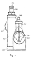
- the jack of Figures 1 to 3 is a stand type jack, in which a stand type jack main body 260 is installed vertically on a base 261; the main body is a cylinder type oil pressure tank coupled with a stand shaft 262 which can move upward and downward under compression.
- a top block 263 is installed on the upper side of the stand shaft 262 and serves as a carrying member; a drive motor 210 with shaft 201 protruding from its two ends is mounted transversely in the cylinder body.
- On one end of the shaft is mounted a small gear wheel 206 which is coupled to a bias mechanism 204 (comprising a curved bias shaft or a bias link rod moved by a bias wheel) by means of large gear wheel 207.
- the bias mechanism drives a crank 209 which is coupled to a gas pump piston 203.
- the gas pump has an intake opening for gas input, an exhaust opening for output of compressed gas and a gas channel communicating with a pressure manometer 264.
- a small gear wheel 206' is mounted which engages a large gear wheel 207'.
- This in turn drives a bias mechanism (including a curved bias shaft or a bias link rod moved by a bias wheel) to cause bias shaft 220 to reciprocate crank set 209'.
- This reciprocating motion is transmitted via a coupling pin 209''' to an oil pump piston rod 209'' which reciprocates within an oil pump cylinder 208.
- a drain circuit piston 205 is used for drain reduction of the jack or to release drain in the non-driven state.
- the large gear wheel 207' has a reduced diameter portion in the periphery of which a circumferential array of holes 207" (which may be screw holes) are formed. These can accommodate an operating rod, so that the oil pump can be driven by back and forth motion by hand.
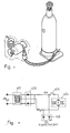
- FIGS 4, 5 and 6 show a coaxial horizontal-type jack.
- the jack is mounted on wheels 273 which are mounted on wheel shaft 272 at one end of the jack body.
- a drive rod 281 driven by a hydraulic oil pressure tank 280 is coupled with a rising arm assembly 274 by a coupling pin 276, the rising arm plate 274 being mounted on a rod 275 which acts as the centre of oscillation. Consequently, as plate 274 swings about rod 275, an upright arm 277 coupled to plate 274 by coupling pin 278 rises and lifts a supporting block 279.
- a common drive motor 210 having a shaft 201 protruding at each end is mounted on one side of the jack body.
- One end of the shaft has a small gear wheel 206 mounted thereon, which drives a bias mechanism 204 (including a curved bias shaft or a bias link rod moved by the bias wheel) via a large gear wheel 207.
- the gas pump has an intake opening for gas input, an exhaust opening for output of compressed gas and a gas channel communicating with a pressure manometer 264.
- the other end of the output shaft of motor 210 has mounted thereon a small transverse gear wheel 206' and which drives a large gear wheel 207'''.
- crank 220' This in turn drives a bias mechanism (including a curved bias shaft or a bias link rod moved by bias wheel) which drives a crank 220'.
- the reciprocating motion of crank 220' is transmitted by a coupling pin 209''' to a piston rod of the oil pump 280.
- a drain circuit piston 205 is provided for draining purposes in order to prevent the drive.
- the rear portion of the large gear wheel is provided with a circumferential array of holes 207'' (which may be screw holes) for accommodating an operating rod which can be driven back and forth by hand to drive the jack oil pump.
- jack devices can be of the AC/DC dual purpose type as shown in Fig. 8.
- a transformer 401 is provided to transform the household power supply into a low voltage output. Its low voltage output end is connected to a rectifier 402 for rectifying the low voltage output and is connected in parallel with a socket 403.
- Socket 403 can be used to supply DC to energise the above said DC motor 404 and drive the air pump or jack. Socket 403 can also be used as a DC output socket for charging purposes. Alternatively an output terminal can be added for this purpose.
- a switch 405 is connected in series with the input of the DC motor 404 to cut off the DC motor 404, when the circuit serves as a charging power supply.
Landscapes
- Engineering & Computer Science (AREA)
- Mechanical Engineering (AREA)
- Life Sciences & Earth Sciences (AREA)
- Geology (AREA)
- Structural Engineering (AREA)
- General Engineering & Computer Science (AREA)
- Reciprocating Pumps (AREA)
- Compressors, Vaccum Pumps And Other Relevant Systems (AREA)
- Types And Forms Of Lifts (AREA)
- Auxiliary Drives, Propulsion Controls, And Safety Devices (AREA)
- Control Of Vehicle Engines Or Engines For Specific Uses (AREA)
- Lubrication Of Internal Combustion Engines (AREA)
- Valve-Gear Or Valve Arrangements (AREA)
- Compressor (AREA)
- Surgical Instruments (AREA)
- Control Of Motors That Do Not Use Commutators (AREA)
Claims (4)
- Fahrzeugheber kombiniert mit einer Luftpumpe, gekennzeichnet durch einen gemeinsamen Drehantriebsmotor (210), der sowhol die Luftpumpe (202) als auch die Ölpumpe (208) betätigt, wobei die Ölpumpe so angeordnet ist, daß sie einen hydraulischen Heber (260, 262, 263; 280, 281, 274 bis 279) aktiviert, und die Ölpumpe eine Ablaßsteuereinrichtung (205) hat, die so eingestellt werden kann, daß sie den Heber abschaltet.
- Fahrzeugheber kombiniert mit einer Luftpumpe nach Anspruch 1, bei welchem sowohl die Ölpumpe (208) als auch die Luftpumpe (202) Ablaßventileinrichtungen (205) haben, die so eingestellt worden können, daß die Luftpumpe und der Heber selektiv abgeschaltet werden können.
- Fahrzeugheber kombiniert mit einer Luftpumpe nach Anspruch 2, bei welchem der Motor (210) eine langgestreckte doppelendige Welle (201) mit von dem Motor jeweils vorstehenden Endabschnitten aufweist, wobei einer der Endabschnitte mit der Luftpumpe (202) und der andere der Endabschnitte über ein Untersetzungsgetriebe (207) mit der Ölpumpe (208) gekoppelt ist, der hydraulische Heber einen insgesamt horizontal angeordneten Hydraulikzylinder (280) aufweist, der einen Kolben (281) in der horizontalen Richtung antreibt, der Kolben (281) mit einem versetzten Abschnitt (276) eines Schwinggestänges (274) gekoppelt ist, welches einen Stützarm (277) in der vertikalen Richtung antreibt, und dar Stützarm einen Stützblock (279) zum Heben eines Fahrzeugs trägt.
- Fahrzeugheber kombiniert mit einer Luftpumpe nach einem vorhergehenden Anspruch, welcher weiterhin einen Netztransformator (401) mit einer Niederspannungsausgangswicklung, die über einen Gleichrichter (402) und einen Schalter (405) mit dem Motor (404) gekoppelt ist, und eine Gleichstrom-Eingangs-/-Ausgangsbuchse aufweist, die parallel zu dem Motor geschaltet ist, so daß der Motor von einer externen Gleichstromspeisung als Alternative zum Netz angetrieben und ein Niederspannungs-Gleichstromausgang von den Klemmen abgenommen werden kann, wenn der Transformator vom Netz aktiviert und der Motor durch den Schalter abgeschaltet ist.
Priority Applications (1)
| Application Number | Priority Date | Filing Date | Title |
|---|---|---|---|
| AT86308292T ATE63531T1 (de) | 1985-10-24 | 1986-10-24 | Hebebock kombiniert mit einer druckluftpumpe und angetrieben von einem gemeinsamen motor. |
Applications Claiming Priority (2)
| Application Number | Priority Date | Filing Date | Title |
|---|---|---|---|
| GB8526270 | 1985-10-24 | ||
| GB858526270A GB8526270D0 (en) | 1985-10-24 | 1985-10-24 | Jack |
Publications (3)
| Publication Number | Publication Date |
|---|---|
| EP0227256A2 EP0227256A2 (de) | 1987-07-01 |
| EP0227256A3 EP0227256A3 (en) | 1988-07-13 |
| EP0227256B1 true EP0227256B1 (de) | 1991-05-15 |
Family
ID=10587203
Family Applications (1)
| Application Number | Title | Priority Date | Filing Date |
|---|---|---|---|
| EP86308292A Expired - Lifetime EP0227256B1 (de) | 1985-10-24 | 1986-10-24 | Hebebock kombiniert mit einer Druckluftpumpe und angetrieben von einem gemeinsamen Motor |
Country Status (5)
| Country | Link |
|---|---|
| EP (1) | EP0227256B1 (de) |
| AT (1) | ATE63531T1 (de) |
| DE (1) | DE3679297D1 (de) |
| ES (1) | ES2022127B3 (de) |
| GB (1) | GB8526270D0 (de) |
Cited By (2)
| Publication number | Priority date | Publication date | Assignee | Title |
|---|---|---|---|---|
| US7225959B2 (en) | 2001-04-30 | 2007-06-05 | Black & Decker, Inc. | Portable, battery-powered air compressor for a pneumatic tool system |
| US7494035B2 (en) | 2001-04-30 | 2009-02-24 | Black & Decker Inc. | Pneumatic compressor |
Families Citing this family (4)
| Publication number | Priority date | Publication date | Assignee | Title |
|---|---|---|---|---|
| US6468047B1 (en) * | 2001-05-22 | 2002-10-22 | Ying-Che Huang | Power pump device |
| CN100425181C (zh) * | 2005-03-08 | 2008-10-15 | 唐斌 | 一种自动左右旋转椅 |
| KR101704056B1 (ko) * | 2011-10-26 | 2017-02-08 | 현대자동차주식회사 | 전동잭 |
| CN109650278B (zh) * | 2019-01-24 | 2025-02-28 | 湖北神百专用汽车有限公司 | 气压千斤顶 |
Family Cites Families (6)
| Publication number | Priority date | Publication date | Assignee | Title |
|---|---|---|---|---|
| GB131805A (de) * | 1900-01-01 | |||
| US1983444A (en) * | 1934-03-22 | 1934-12-04 | Dry William Alfred | Pneumatic pump and jack |
| US2458590A (en) * | 1946-04-19 | 1949-01-11 | George W Harris | Combination automobile jack and engine starting device |
| CH462411A (de) * | 1967-12-29 | 1968-09-15 | Wiederkehr Hans | Wagenheber |
| DE3108208A1 (de) * | 1981-03-04 | 1982-09-16 | Eckhart Dipl.-Ing. 4544 Ladbergen Dewert | Wagenheber fuer kraftfahrzeuge oder klein-nutzfahrzeuge |
| DE3470514D1 (en) * | 1983-02-24 | 1988-05-26 | Emgi Engineering Srl | Electrically operated lifting jack |
-
1985
- 1985-10-24 GB GB858526270A patent/GB8526270D0/en active Pending
-
1986
- 1986-10-24 DE DE8686308292T patent/DE3679297D1/de not_active Expired - Lifetime
- 1986-10-24 EP EP86308292A patent/EP0227256B1/de not_active Expired - Lifetime
- 1986-10-24 AT AT86308292T patent/ATE63531T1/de not_active IP Right Cessation
- 1986-10-24 ES ES86308292T patent/ES2022127B3/es not_active Expired - Lifetime
Cited By (2)
| Publication number | Priority date | Publication date | Assignee | Title |
|---|---|---|---|---|
| US7225959B2 (en) | 2001-04-30 | 2007-06-05 | Black & Decker, Inc. | Portable, battery-powered air compressor for a pneumatic tool system |
| US7494035B2 (en) | 2001-04-30 | 2009-02-24 | Black & Decker Inc. | Pneumatic compressor |
Also Published As
| Publication number | Publication date |
|---|---|
| EP0227256A3 (en) | 1988-07-13 |
| GB8526270D0 (en) | 1985-11-27 |
| EP0227256A2 (de) | 1987-07-01 |
| ES2022127B3 (es) | 1991-12-01 |
| DE3679297D1 (de) | 1991-06-20 |
| ATE63531T1 (de) | 1991-06-15 |
Similar Documents
| Publication | Publication Date | Title |
|---|---|---|
| EP0227256B1 (de) | Hebebock kombiniert mit einer Druckluftpumpe und angetrieben von einem gemeinsamen Motor | |
| KR880000562B1 (ko) | 차량용 자동방향 전환장치 | |
| US4678162A (en) | Jack having the pneumatic air pump functions and using a common drive motor | |
| US4678164A (en) | Jack having the pneumatic air pump functions and using a common drive motor | |
| CN2445994Y (zh) | 电动液压卧式千斤顶 | |
| CN2428377Y (zh) | 集成液压举升器 | |
| CN2511663Y (zh) | 全液压电动叉车 | |
| CN220519167U (zh) | 一种压缩垃圾车动力系统及压缩垃圾车 | |
| CN219769834U (zh) | 一种多功能随车工具 | |
| CN220094204U (zh) | 汽车减震器贮油外缸高速抛光处理机 | |
| CN110844840A (zh) | 一种便于清洗和照明的汽车维修台 | |
| CN206219117U (zh) | 车辆自顶升装置 | |
| CN114560414B (zh) | 一种电动千斤顶 | |
| CN1241820C (zh) | 电动千斤顶 | |
| CN106517026A (zh) | 车辆自顶升装置 | |
| CN2346954Y (zh) | 电子打气筒 | |
| CN2334740Y (zh) | 电动液压千斤顶 | |
| CN2402565Y (zh) | 液压救援起复设备 | |
| CN2192608Y (zh) | 举升机 | |
| CN209600183U (zh) | 一种汽车轮胎维修专用拆装装置 | |
| CN2220464Y (zh) | 电动液压千斤顶 | |
| CN2288322Y (zh) | 手动气动液动电爆驱动瓶头阀 | |
| CN2191142Y (zh) | 一种汽车举升机 | |
| CN2631873Y (zh) | 牵引汽车牵引座液压升降装置 | |
| CN223030953U (zh) | 一种小空间内汽车移位设备 |
Legal Events
| Date | Code | Title | Description |
|---|---|---|---|
| PUAI | Public reference made under article 153(3) epc to a published international application that has entered the european phase |
Free format text: ORIGINAL CODE: 0009012 |
|
| AK | Designated contracting states |
Kind code of ref document: A2 Designated state(s): AT BE CH DE ES FR GB GR IT LI LU NL SE |
|
| PUAL | Search report despatched |
Free format text: ORIGINAL CODE: 0009013 |
|
| RHK1 | Main classification (correction) |
Ipc: B66F 3/44 |
|
| AK | Designated contracting states |
Kind code of ref document: A3 Designated state(s): AT BE CH DE ES FR GB GR IT LI LU NL SE |
|
| 17P | Request for examination filed |
Effective date: 19890110 |
|
| 17Q | First examination report despatched |
Effective date: 19891124 |
|
| GRAA | (expected) grant |
Free format text: ORIGINAL CODE: 0009210 |
|
| ITF | It: translation for a ep patent filed | ||
| AK | Designated contracting states |
Kind code of ref document: B1 Designated state(s): AT BE CH DE ES FR GB GR IT LI LU NL SE |
|
| PG25 | Lapsed in a contracting state [announced via postgrant information from national office to epo] |
Ref country code: GR Free format text: LAPSE BECAUSE OF FAILURE TO SUBMIT A TRANSLATION OF THE DESCRIPTION OR TO PAY THE FEE WITHIN THE PRESCRIBED TIME-LIMIT Effective date: 19910515 |
|
| REF | Corresponds to: |
Ref document number: 63531 Country of ref document: AT Date of ref document: 19910615 Kind code of ref document: T |
|
| REF | Corresponds to: |
Ref document number: 3679297 Country of ref document: DE Date of ref document: 19910620 |
|
| ET | Fr: translation filed | ||
| PGFP | Annual fee paid to national office [announced via postgrant information from national office to epo] |
Ref country code: GB Payment date: 19911022 Year of fee payment: 6 |
|
| PG25 | Lapsed in a contracting state [announced via postgrant information from national office to epo] |
Ref country code: AT Effective date: 19911024 |
|
| PG25 | Lapsed in a contracting state [announced via postgrant information from national office to epo] |
Ref country code: SE Effective date: 19911025 |
|
| PGFP | Annual fee paid to national office [announced via postgrant information from national office to epo] |
Ref country code: ES Payment date: 19911029 Year of fee payment: 6 |
|
| PG25 | Lapsed in a contracting state [announced via postgrant information from national office to epo] |
Ref country code: LU Free format text: LAPSE BECAUSE OF NON-PAYMENT OF DUE FEES Effective date: 19911031 Ref country code: LI Effective date: 19911031 Ref country code: CH Effective date: 19911031 Ref country code: BE Effective date: 19911031 |
|
| PGFP | Annual fee paid to national office [announced via postgrant information from national office to epo] |
Ref country code: FR Payment date: 19911031 Year of fee payment: 6 |
|
| PGFP | Annual fee paid to national office [announced via postgrant information from national office to epo] |
Ref country code: DE Payment date: 19911230 Year of fee payment: 6 |
|
| PLBE | No opposition filed within time limit |
Free format text: ORIGINAL CODE: 0009261 |
|
| STAA | Information on the status of an ep patent application or granted ep patent |
Free format text: STATUS: NO OPPOSITION FILED WITHIN TIME LIMIT |
|
| BERE | Be: lapsed |
Owner name: YANG TAI-HER Effective date: 19911031 |
|
| PG25 | Lapsed in a contracting state [announced via postgrant information from national office to epo] |
Ref country code: NL Effective date: 19920501 |
|
| 26N | No opposition filed | ||
| NLV4 | Nl: lapsed or anulled due to non-payment of the annual fee | ||
| REG | Reference to a national code |
Ref country code: CH Ref legal event code: PL |
|
| PG25 | Lapsed in a contracting state [announced via postgrant information from national office to epo] |
Ref country code: GB Effective date: 19921024 |
|
| PG25 | Lapsed in a contracting state [announced via postgrant information from national office to epo] |
Ref country code: ES Free format text: LAPSE BECAUSE OF THE APPLICANT RENOUNCES Effective date: 19921026 |
|
| GBPC | Gb: european patent ceased through non-payment of renewal fee |
Effective date: 19921024 |
|
| PG25 | Lapsed in a contracting state [announced via postgrant information from national office to epo] |
Ref country code: FR Effective date: 19930630 |
|
| PG25 | Lapsed in a contracting state [announced via postgrant information from national office to epo] |
Ref country code: DE Effective date: 19930701 |
|
| REG | Reference to a national code |
Ref country code: FR Ref legal event code: ST |
|
| EUG | Se: european patent has lapsed |
Ref document number: 86308292.1 Effective date: 19920510 |
|
| REG | Reference to a national code |
Ref country code: ES Ref legal event code: FD2A Effective date: 20001102 |
|
| PG25 | Lapsed in a contracting state [announced via postgrant information from national office to epo] |
Ref country code: IT Free format text: LAPSE BECAUSE OF NON-PAYMENT OF DUE FEES;WARNING: LAPSES OF ITALIAN PATENTS WITH EFFECTIVE DATE BEFORE 2007 MAY HAVE OCCURRED AT ANY TIME BEFORE 2007. THE CORRECT EFFECTIVE DATE MAY BE DIFFERENT FROM THE ONE RECORDED. Effective date: 20051024 |