EP0227265B1 - Appareil et méthode pour générer des radiations laser dans le domaine des rayons X moux dans une colonne de plasma confiné utilisant un laser à picosecondes - Google Patents
Appareil et méthode pour générer des radiations laser dans le domaine des rayons X moux dans une colonne de plasma confiné utilisant un laser à picosecondes Download PDFInfo
- Publication number
- EP0227265B1 EP0227265B1 EP86308473A EP86308473A EP0227265B1 EP 0227265 B1 EP0227265 B1 EP 0227265B1 EP 86308473 A EP86308473 A EP 86308473A EP 86308473 A EP86308473 A EP 86308473A EP 0227265 B1 EP0227265 B1 EP 0227265B1
- Authority
- EP
- European Patent Office
- Prior art keywords
- laser
- ions
- plasma
- laser beam
- plasma column
- Prior art date
- Legal status (The legal status is an assumption and is not a legal conclusion. Google has not performed a legal analysis and makes no representation as to the accuracy of the status listed.)
- Expired - Lifetime
Links
- 238000000034 method Methods 0.000 title claims description 14
- 150000002500 ions Chemical class 0.000 claims description 20
- 229910052799 carbon Inorganic materials 0.000 claims description 12
- OKTJSMMVPCPJKN-UHFFFAOYSA-N Carbon Chemical compound [C] OKTJSMMVPCPJKN-UHFFFAOYSA-N 0.000 claims description 8
- 238000001816 cooling Methods 0.000 claims description 6
- 239000000463 material Substances 0.000 claims description 6
- 229910052786 argon Inorganic materials 0.000 claims description 5
- 229910052743 krypton Inorganic materials 0.000 claims description 5
- 230000005855 radiation Effects 0.000 claims description 5
- 230000005284 excitation Effects 0.000 claims description 4
- 229910052782 aluminium Inorganic materials 0.000 claims description 3
- -1 carbon ions Chemical class 0.000 claims description 3
- 229910052754 neon Inorganic materials 0.000 claims description 3
- 229910052760 oxygen Inorganic materials 0.000 claims description 3
- 229910052710 silicon Inorganic materials 0.000 claims description 3
- 238000007493 shaping process Methods 0.000 claims 1
- 210000002381 plasma Anatomy 0.000 description 37
- 230000003993 interaction Effects 0.000 description 6
- 238000004804 winding Methods 0.000 description 5
- 239000007789 gas Substances 0.000 description 4
- 229920000049 Carbon (fiber) Polymers 0.000 description 3
- 238000013459 approach Methods 0.000 description 3
- 239000004917 carbon fiber Substances 0.000 description 3
- 239000013078 crystal Substances 0.000 description 3
- 239000011521 glass Substances 0.000 description 3
- VNWKTOKETHGBQD-UHFFFAOYSA-N methane Chemical compound C VNWKTOKETHGBQD-UHFFFAOYSA-N 0.000 description 3
- 230000003287 optical effect Effects 0.000 description 3
- 230000003466 anti-cipated effect Effects 0.000 description 2
- 239000004020 conductor Substances 0.000 description 2
- 238000010586 diagram Methods 0.000 description 2
- 230000009977 dual effect Effects 0.000 description 2
- 239000011888 foil Substances 0.000 description 2
- 239000013307 optical fiber Substances 0.000 description 2
- 238000005086 pumping Methods 0.000 description 2
- 239000000523 sample Substances 0.000 description 2
- XLYOFNOQVPJJNP-UHFFFAOYSA-N water Substances O XLYOFNOQVPJJNP-UHFFFAOYSA-N 0.000 description 2
- 229910052779 Neodymium Inorganic materials 0.000 description 1
- 230000015572 biosynthetic process Effects 0.000 description 1
- 230000003111 delayed effect Effects 0.000 description 1
- 238000011161 development Methods 0.000 description 1
- 238000010894 electron beam technology Methods 0.000 description 1
- 238000005516 engineering process Methods 0.000 description 1
- 230000002349 favourable effect Effects 0.000 description 1
- 239000000835 fiber Substances 0.000 description 1
- 238000007429 general method Methods 0.000 description 1
- 229910052734 helium Inorganic materials 0.000 description 1
- 229910052739 hydrogen Inorganic materials 0.000 description 1
- 230000000977 initiatory effect Effects 0.000 description 1
- 238000005259 measurement Methods 0.000 description 1
- QEFYFXOXNSNQGX-UHFFFAOYSA-N neodymium atom Chemical compound [Nd] QEFYFXOXNSNQGX-UHFFFAOYSA-N 0.000 description 1
- 239000002243 precursor Substances 0.000 description 1
- 150000003384 small molecules Chemical class 0.000 description 1
- 239000007787 solid Substances 0.000 description 1
- 125000006850 spacer group Chemical group 0.000 description 1
- 239000013077 target material Substances 0.000 description 1
Images


Classifications
-
- G—PHYSICS
- G21—NUCLEAR PHYSICS; NUCLEAR ENGINEERING
- G21B—FUSION REACTORS
- G21B1/00—Thermonuclear fusion reactors
- G21B1/11—Details
- G21B1/23—Optical systems, e.g. for irradiating targets, for heating plasma or for plasma diagnostics
-
- H—ELECTRICITY
- H01—ELECTRIC ELEMENTS
- H01S—DEVICES USING THE PROCESS OF LIGHT AMPLIFICATION BY STIMULATED EMISSION OF RADIATION [LASER] TO AMPLIFY OR GENERATE LIGHT; DEVICES USING STIMULATED EMISSION OF ELECTROMAGNETIC RADIATION IN WAVE RANGES OTHER THAN OPTICAL
- H01S4/00—Devices using stimulated emission of electromagnetic radiation in wave ranges other than those covered by groups H01S1/00, H01S3/00 or H01S5/00, e.g. phonon masers, X-ray lasers or gamma-ray lasers
-
- Y—GENERAL TAGGING OF NEW TECHNOLOGICAL DEVELOPMENTS; GENERAL TAGGING OF CROSS-SECTIONAL TECHNOLOGIES SPANNING OVER SEVERAL SECTIONS OF THE IPC; TECHNICAL SUBJECTS COVERED BY FORMER USPC CROSS-REFERENCE ART COLLECTIONS [XRACs] AND DIGESTS
- Y02—TECHNOLOGIES OR APPLICATIONS FOR MITIGATION OR ADAPTATION AGAINST CLIMATE CHANGE
- Y02E—REDUCTION OF GREENHOUSE GAS [GHG] EMISSIONS, RELATED TO ENERGY GENERATION, TRANSMISSION OR DISTRIBUTION
- Y02E30/00—Energy generation of nuclear origin
- Y02E30/10—Nuclear fusion reactors
Definitions
- the invention comprises a method and apparatus for generating soft X-ray lasing action by focusing a powerful picoseond laser on a confined plasma column.
- Soft X-ray lasers have gained recent attention because of the interesting scientific potential for such devices. It is believed that X-ray lasers would have the capability of forming holographic interference images which could, for example, be used to study the detailed three-dimensional structure of small molecules such as DNA. Other significant applications are anticipated.
- the potential for X-ray lasers is described in the October 30, 1984 editions of THE NEWARK STAR LEDGER and THE WALL STREET JOURNAL, as well as the April 2, 1985 edition of THE NEW YORK TIMES.
- the CO2 laser could be replaced by a neodymium glass laser.
- Nd:G glass lasers are discussed in a different enviroment in US-A-4,058,486.
- An approach to a soft X-ray laser with a single laser and rapid plasma cooling after the laser pulse was disclosed in a publication entitled "Population Inversion and Gain Measurements for Soft X-Ray Laser Development in a Magnetically Confined Plasma Column,” by Suckewer, et al. Quantum Electronics, Vol. QE19, December 1983.
- the invention comprises apparatus for use with apparatus for generating soft X-ray lasing action as set out in claim 1.
- the invention comprises a method for generating population inversion and soft X-ray lasing action as set out in claim 9.
- a target material 12 such as carbon fiber is housed within a vacuum vessel 14. Alternatively a carbon foil could be employed or a fiber or foil of a multi-Z material.
- a pair of differential vacuum pumps 30 and 32 bring the vacuum in chamber 14 down to the neighborhood of 1.33 x 10 ⁇ 5 Pa (10 ⁇ 7 Torr).
- a CO2 laser 18 produces a beam 20 focused by mirror 22 on carbon fiber target 12.
- Beam 20 preferably comprises a pulse having a duration of 20 - 30 nanoseconds and an energy level of 1.5 KJ. While a pulse duration of 20 - 30 nanoseconds is preferred, a time scale in the neighborhood of 10 - 100 nanoseconds would be acceptable.
- CO2 laser beam 20 typically has a length approximately the length of the carbon fiber target 12 and a width slightly wider than target 12. Therefore for a target 12 1-2 cm long and 35 to 100 microns thick the cross-section of the CO2 laser beam might be 1-2 cm long and 100-200 microns wide.
- CO2 laser beam 20 creates a plasma which is confined to a column shape by helical magnets 16. The plasma column 15 formed thereby is typically 1 - 2 centimeters long and about 1 millimeter in diameter.
- the magnetic field created by the helical magnet 16 has a strength in the neighborhood of 10 - 15 TesPa (100-150KGauss).
- the plasma column 15 confined by the magnetic field B z cools rapidly by radiation losses and becomes a very good medium for creating relatively high gain in the soft X-ray region of 1-2 x 10 ⁇ 8m (100 - 200 Angstroms). It has been found that radiation losses for the plasma column 15 are more efficient for fast cooling than through cooling by adiabatic expansion. It is important that the confined plasma column 15 be relatively long, and uniform along its axis and that it have a higher density than the freely expanding column at the time when the highest population inversion (gain) is expected.
- the plasma column 15 is subjected to a high power picosecond laser pulse 26.
- Laser pulse 26 is created by high power picosecond laser 24 and focused by mirror 28 onto the plasma column 15.
- the high power picosecond pulse 26 is focused on the plasma column 15 approximately 20 to 100 nanoseconds after the CO2 laser pulse 20 has created the plasma column 15.
- High power loser pulse 26 has a pulse duration time of approximately 1 picosecond and a power output in the range of 1015 - 1017 W/cm2.
- the powerful picosecond laser beam 26 is smaller in cross-section than CO2 laser beam 20 and is focused along the central part of the plasma column 15 which is approximately 50 micrometers in diameter.
- Power for the helical magnet 16 is provided by a pulse power system 38.
- Laser beams 20 and 26 are strongly focused in one direction as shown in Figure 2 and slightly focused in the other perpendicular direction as shown in Figure 1. Therefore laser beams 20 and 26 can be accurately described as line focused beams since they are focused along the length of the target 12 in order to create an elongated plasma column 15 with small radial dimensions. Both beams 20 and 26 are near-perpendicular to plasma column 15 as can be appreciated from Figure 2.
- a variety of instruments are used to monitor the total radiation beam 34 from the apparatus 10.
- the beam 34 shown in Figure 1 is divided by beam splitter mirror 40 into two beams 44 and 46.
- Beam 44 is analyzed by XUV spectrometer 50 (X-ray part of the beam) whereas beam 46 is reflected by mirror 42 into air monochrometer 48 (UV part of the beam).
- the outputs from the air monochrometer 48 and XUV spectrometer 50 provide some of the inputs to data acquisition system circuit 52.
- Another portion of the beam 34 passes to another beam splitter 40 where a portion of the beam 44 is monitored by XUV monochrometer 62 (X-ray part of the beam).
- the other portion of the beam 46 is, reflected off mirror 42 into Pin diode detector 60 (UV part of the beam).
- Pin diode detector 60 and the XUV monochrometer 62 are likewise forwarded to data acquisition system 52.
- a streak camera 54, a vacuum XUV spectrometer 56, and an air UV spectrometer 58 also monitor the conditions inside of vacuum vessel 14 and forward the data to data acquisition system 52.
- FIG 2 is a detail mechanical illustration of the vacuum vessel 14 and the associated elements which are shown more generally in Figure 1.
- Optical fiber probes 66 are directed towards the target area 12 where the plasma column 15 is formed. The output from optical probes 66 forms the input for the streak camera 54.
- the vacuum XUX spectrometer 56 and the air UX spectrometer 58 and other instruments are connected to vacuum chamber 14 of apparatus 10 and can be arranged to view the plasma 15 through a system of conventional mirrors and lenses as well as through optical fibers 66.
- the diameter DR of the vacuum vessel 14 is preferably in the neighborhood of 5 centimeters.
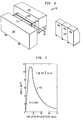
- Figures 3A, 3B and 4 all illustrate various aspects of the helical magnet 16.
- Figure 3A is a cross-sectional view of the helical solenoid magnet 16.
- Magnet 16 includes a core aperture 68 having a diameter DR in the neighborhood of 5 centimeters as previously described.
- a pair of end plates 70 held together by tie rod 76 support the windings 71.
- Power is supplied to windings 71 by the pulse power system 38 illustrated in Figure 1.
- Figure 3B is an end view of the helical solenoid magnet 16 illustrated in Figure 3A.
- the right hand portion of Figure 4 shows the location of the conductors 80 that form parts of the winding 71 illustrated in Figure 3A.
- the right hand side of Figure 4 also shows the preferred dimensional relationship between the helical magnetic section 16 and the radial axis R cm and the longitudinal axis Z cm . Those preferred dimensions are as follows:
- FIG. 5 illustrates in schematic fashion the details of the powerful picosecond laser 24.
- Picosecond laser 24 is typical of the type of lasers that can now be constructed. There are other techniques that could be used as well. This particular technique is offered only to show the preferred embodiment for use with this invention and is not meant to limit the scope of other powerful picosecond lasers that could be used as well.
- a mode locked Nd:YAG laser 82 produces an output 84.
- the output 84 goes to a KTP doubler 85 whose output is split and forms the input to a dual jet dye laser 86 and an Nd:YAG amplifier 92.
- the output from the dual jet dye laser 86 forms input to cavity dumper 88 the output of which forms the input to a three stage dye amplifier 90.
- the output from Nd:YAG amplifier 92 passes through a KD*P doubler 94 which pumps the three stage dye amplifier 90.
- the output of the KD*P doubler 94 is optically delayed by device 96 to correlate with the peak gain of the final dye amplifier 98 for which it provides pumping input.
- the output from the three stage dye amplifier 90 is the input for final dye amplifier 98.
- the output from final dye amplfier 98 is doubled in doubler crystal 100 and forwarded to mixer crystal 102.
- the output from mixer crystal 102 forms the input to preliminary KrF amplifier 104 which feeds the final KrF amplifier 106.
- the elements just described which form part of the powerful picosecond laser apparatus 24 are conventional elements and, the method and apparatus for forming the powerful picosecond laser output 26 are believed to be within the abilities of one of ordinary skill in the art.
- the CO2 laser 18 illustrated in Figure 6 is believed to be generally conventional.
- the elements of the CO2 laser 18 can, for example, be purchased individually from Maxwell Laboratory Inc., 8888 Bell Bowa Avenue, San Diego, California 92128.
- a Marx generator 108 provides the initial power for the E-beam chamber 112.
- Sustainer bank oil tank 110 contains high voltage elements to provide a high voltage discharge in laser chamber 114.
- the electron beam formed in E-beam chamber 112 passes through laser chamber 114 for initiation discharge in laser chamber 114.
- the discharge in laser chamber 114 creates lasing action and the resulting CO2 laser beam 20 is subsequently focused by optical system 116.
- the CO2 beam 20 is shown schematically as it is emitted from the optical system 116.
- It preferably has a pulse width t p of 20 to 30 nanoseconds and an energy level of 1.5KJ. While the powerful picosecond laser 24 illustrated in Figure 5 and the lower power CO2 laser 18 illustrated in Figure 6 have been described in sufficient detail for one of the ordinary skill in the art to make and use lasers 18 and 24, it will be appreciated that a detailed understanding of their operation structure. is not necessary for an understanding of the overall method and apparatus of the preferred embodiment of the invention 10.
- a target 12 such as carbon is placed in the vacuum vessel 14 which is then evacuated.
- CO2 laser 18 is then activated causing laser beam 20 to impinge upon carbon target 12.
- the 1.5 K joule, 20 - 30 nanosecond pulse causes the carbon target 12 to ionize.
- the plasma column 15 Approximately 20 - 100 nanoseconds after laser beam 20 has created the plasma column 15, it is subjected to the powerful picosecond laser beam 26 which has a pulse duration t p of approximately 1 picosecond and power in the neighborhood of 1015 - 1017 W/cm2. Powerful picosecond laser beam 26 is focused along the central part of the plasma column which is approximately 50 micrometers in diameter.
- the present invention 10 comprehends interacting a very powerful picosecond laser with a plasma column.
- the unique plasma column 15 formed according to the present invention 10 has very favorable conditions for population inversion and gain due to its fast radiation cooling. Hence a significantly increased population inversion by fast selective excitation and ionization of ions by multiphoton processes induced by powerful picosecond laser leads to high gain and lasing action.
- Figure 7 illustrates the nature of the output pulse 120 which occurs with the interaction of the powerful picosecond laser pulse 26 with CVI ions in a confined plasma column 15.
- a maximum gain of approximately 11 measured in terms of K(cm ⁇ 1) is shown approximately 7 picoseconds after the powerful picosecond laser pulse 26.
- Soft X-ray laser beam 120 has a wavelength of 182 Angstroms. While the output laser beam 120 is shown in the soft X-ray lasing range of 1 - 2 x 10 ⁇ 8m (100 - 200 Angstroms), it is likely that higher gains can also be produced creating wavelengths in the shorter 0.6 - 0.7 ⁇ 10 ⁇ 8m (60 - 70 Angstrom) region using other than carbon target (e.g. higher Z materials). Moreover, theoretical modelling suggests that it is possible to predict and produce lasing action in the 0.1 - 0.2 ⁇ 10 ⁇ 8m (10 - 20 Angstrom) range using the same general method and apparatus but using more powerful lasers and high-Z materials as targets.
- Multiphoton ionization of Ar, Kr, Xe, U up to ArVII, KrVII, XeIX and UXI has already been observed. It is therefore believed possible to create a very high gain in the region of 1 - 2 x 10 ⁇ 8m (100-200 Angstroms) by the interaction of a powerful picosecond laser 26 near resonant multiphoton excitation frequencies of Ar VIII as well as Kr VIII or Kr IX.
Landscapes
- Physics & Mathematics (AREA)
- Engineering & Computer Science (AREA)
- Electromagnetism (AREA)
- Plasma & Fusion (AREA)
- General Engineering & Computer Science (AREA)
- High Energy & Nuclear Physics (AREA)
- Optics & Photonics (AREA)
- Lasers (AREA)
- X-Ray Techniques (AREA)
Claims (13)
- Appareil destiné à être utilisé avec un appareil pour générer une action laser rayons X mous comprenant:
une cible (12);
un premier moyen de laser (18) pour produire un premier faisceau laser (20) présentant une durée d'impulsion se situant entre 10 et 100 nanosecondes et une puissance se situant entre 40 et 80 GW pour interagir avec ladite cible (12) et pour générer un plasma comportant des ions en son sein;
un moyen de champ magnétique (16) pour confiner ledit plasma et pour le conformer selon sensiblement la forme d'une colonne (15);
un second moyen de laser (24) pour produire un second faisceau laser (26) présentant une durée d'impulsion se situant entre 1 et 2 picosecondes et une puissance supérieure à 10¹⁵ W/cm² pour interagir avec ladite colonne de plasma (15) afin de produire une excitation sélective intense desdits ions pour créer une inversion de population et pour obtenir une action de laser rayons X mous. - Appareil selon la revendication 1, incluant en outre:
un moyen de commande pour commander ledit second moyen de laser (24) de telle sorte que ledit second faisceau laser (26) interagisse avec ladite colonne de plasma (15) entre 20 et 100 nanosecondes après que ledit plasma a été généré par ledit premier faisceau laser (20). - Appareil selon l'une quelconque des revendications 1 et 2, dans lequel ledit moyen de champ magnétique (16) crée un champ magnétique présentant une intensité de 10 Tesla (B = 100 kGauss).
- Appareil selon l'une quelconque des revendications 1 à 3, dans lequel ladite colonne de plasma (15) présente un diamètre d'approximativement 1 millimètre.
- Appareil selon l'une quelconque des revendications 1 à 4, dans lequel lesdits ions contenus dans ladite colonne de plasma (15) comprennent au moins un élément sélectionné parmi le groupe comprenant le C, l'O et le Ne.
- Appareil selon la revendication 5, dans lequel lesdits ions comprennent des ions de carbone.
- Appareil selon l'une quelconque des revendications 1 à 6, dans lequel lesdits ions contenus dans ladite colonne de plasma (15) comprennent au moins un élément sélectionné parmi le groupe comprenant l'Al, le Si, l'Ar, le Kr et le Mo.
- Appareil selon l'une quelconque des revendications 1 à 7, dans lequel ledit premier moyen de laser (18) comprend un laser CO₂.
- Procédé de génération d'une inversion de population et d'une action de laser rayons X mous comprenant les étapes de:
génération d'un premier faisceau laser (20) présentant une durée d'impulsion se situant entre 10 et 100 nanosecondes et une puissance se situant entre 40 et 80 GW;
création d'un plasma comportant des ions en son sein en faisant arriver en incidence ledit premier faisceau laser (20) sur une cible (12);
génération d'un champ magnétique (16) afin de confiner ledit plasma et conformation dudit plasma sensiblement selon la forme d'une colonne (15);
génération d'un second faisceau laser présentant une durée d'impulsion qui se situe entre 1 et 2 picosecondes et une puissance qui est supérieure à 10¹⁵ W/cm²;
refroidissement de ladite colonne de plasma (15) au moyen d'un refroidissement par rayonnement puis interaction dudit second faisceau laser (26) avec ladite colonne de plasma (15) pour produire une excitation sélective intense desdits ions afin de créer une inversion de population et d'obtenir une action de laser rayons X mous. - Procédé selon la revendication 9, dans lequel lesdits ions sont formés à partir d'un matériau comprenant au moins un élément sélectionné parmi le groupe comprenant le C, l'O et le Ne.
- Procédé selon la revendication 10, dans lequel lesdits ions sont des ions de carbone.
- Procédé selon la revendication 9, dans lequel lesdits ions sont formés à partir d'un matériau comprenant au moins un élément sélectionné parmi le groupe qui comprend l'Al, le Si, l'Ar, le Kr et le Mo.
- Procédé selon l'une quelconque des revendications 9 à 12, dans lequel ledit premier faisceau laser (20) est généré au moyen d'un laser CO₂.
Applications Claiming Priority (2)
| Application Number | Priority Date | Filing Date | Title |
|---|---|---|---|
| US794133 | 1985-11-01 | ||
| US06/794,133 US4704718A (en) | 1985-11-01 | 1985-11-01 | Apparatus and method for generating soft X-ray lasing action in a confined plasma column through the use of a picosecond laser |
Publications (3)
| Publication Number | Publication Date |
|---|---|
| EP0227265A2 EP0227265A2 (fr) | 1987-07-01 |
| EP0227265A3 EP0227265A3 (en) | 1988-09-21 |
| EP0227265B1 true EP0227265B1 (fr) | 1994-01-26 |
Family
ID=25161813
Family Applications (1)
| Application Number | Title | Priority Date | Filing Date |
|---|---|---|---|
| EP86308473A Expired - Lifetime EP0227265B1 (fr) | 1985-11-01 | 1986-10-30 | Appareil et méthode pour générer des radiations laser dans le domaine des rayons X moux dans une colonne de plasma confiné utilisant un laser à picosecondes |
Country Status (6)
| Country | Link |
|---|---|
| US (1) | US4704718A (fr) |
| EP (1) | EP0227265B1 (fr) |
| JP (1) | JPH07118573B2 (fr) |
| AU (1) | AU576303B2 (fr) |
| CA (1) | CA1277782C (fr) |
| DE (1) | DE3689586T2 (fr) |
Families Citing this family (28)
| Publication number | Priority date | Publication date | Assignee | Title |
|---|---|---|---|---|
| US4870648A (en) * | 1987-08-07 | 1989-09-26 | The United States Department Of Energy | X-ray beamsplitter |
| GB8821140D0 (en) * | 1988-09-09 | 1988-10-12 | British Telecomm | Laser systems |
| JP2879343B2 (ja) * | 1989-03-29 | 1999-04-05 | 理化学研究所 | 再結合レーザー |
| US4979203A (en) * | 1989-06-19 | 1990-12-18 | Princeton X-Ray Laser | X-ray laser microscope apparatus |
| US5016250A (en) * | 1989-10-18 | 1991-05-14 | The United States Of America As Represented By The United States Department Of Energy | X-ray lasers and methods utilizing two component driving illumination provided by optical laser means of relatively low energy and small physical size |
| US4939744A (en) * | 1989-11-15 | 1990-07-03 | United States Of America As Represented By The Secretary Of Commerce | Method and apparatus for producing a photopumped VUV laser in MO6+ ion-containing plasma |
| US5177774A (en) * | 1991-08-23 | 1993-01-05 | Trustees Of Princeton University | Reflection soft X-ray microscope and method |
| US5317574A (en) * | 1992-12-31 | 1994-05-31 | Hui Wang | Method and apparatus for generating x-ray and/or extreme ultraviolet laser |
| US5394411A (en) * | 1994-02-16 | 1995-02-28 | University Of Maryland, College Park | Method for producing high intensity optical through x-ray waveguide and applications |
| US5680429A (en) * | 1995-01-18 | 1997-10-21 | Shimadzu Corporation | X-ray generating apparatus and X-ray microscope |
| US5578831A (en) * | 1995-03-23 | 1996-11-26 | Associated Universities, Inc. | Method and apparatus for charged particle propagation |
| FR2740898B1 (fr) * | 1995-11-06 | 1998-01-30 | Marie G R P | Dispositif provoquant et utilisant la "microfusion" thermonuclaire |
| JP3186567B2 (ja) * | 1996-02-23 | 2001-07-11 | トヨタ自動車株式会社 | X線レーザー発生装置と発生方法 |
| WO2000060909A1 (fr) * | 1999-03-31 | 2000-10-12 | Japan As Represented By Director General Of Agency Of Industrial Science And Technology | Source de lumiere laser plasma et procede de production de rayonnement l'utilisant |
| US6320937B1 (en) * | 2000-04-24 | 2001-11-20 | Takayasu Mochizuki | Method and apparatus for continuously generating laser plasma X-rays by the use of a cryogenic target |
| US6972421B2 (en) * | 2000-06-09 | 2005-12-06 | Cymer, Inc. | Extreme ultraviolet light source |
| US6973164B2 (en) * | 2003-06-26 | 2005-12-06 | University Of Central Florida Research Foundation, Inc. | Laser-produced plasma EUV light source with pre-pulse enhancement |
| FR2871622B1 (fr) * | 2004-06-14 | 2008-09-12 | Commissariat Energie Atomique | Dispositif de generation de lumiere dans l'extreme ultraviolet et application a une source de lithographie par rayonnement dans l'extreme ultraviolet |
| US7308007B2 (en) * | 2004-12-23 | 2007-12-11 | Colorado State University Research Foundation | Increased laser output energy and average power at wavelengths below 35 nm |
| DE102005014433B3 (de) * | 2005-03-24 | 2006-10-05 | Xtreme Technologies Gmbh | Verfahren und Anordnung zur effizienten Erzeugung von kurzwelliger Strahlung auf Basis eines lasererzeugten Plasmas |
| JP2007137265A (ja) * | 2005-11-18 | 2007-06-07 | Matsushita Electric Ind Co Ltd | 自転車 |
| JP5075389B2 (ja) * | 2006-10-16 | 2012-11-21 | ギガフォトン株式会社 | 極端紫外光源装置 |
| JP5576079B2 (ja) * | 2008-09-29 | 2014-08-20 | ギガフォトン株式会社 | 極端紫外光源装置 |
| JP2010103499A (ja) * | 2008-09-29 | 2010-05-06 | Komatsu Ltd | 極端紫外光源装置および極端紫外光生成方法 |
| US8282634B2 (en) * | 2009-01-14 | 2012-10-09 | Tyco Healthcare Group Lp | Apparatus, system, and method for performing an electrosurgical procedure |
| US20110089834A1 (en) * | 2009-10-20 | 2011-04-21 | Plex Llc | Z-pinch plasma generator and plasma target |
| FR3008822B1 (fr) * | 2013-07-22 | 2015-09-18 | Ecole Polytech | Creation d'isotopes par faisceaux laser |
| US20240237183A1 (en) * | 2022-08-30 | 2024-07-11 | Research Instruments Corporation | Picosecond laser-driven plasma x-ray source |
Family Cites Families (4)
| Publication number | Priority date | Publication date | Assignee | Title |
|---|---|---|---|---|
| US4058486A (en) * | 1972-12-29 | 1977-11-15 | Battelle Memorial Institute | Producing X-rays |
| DE2500429A1 (de) * | 1975-01-07 | 1976-07-08 | Atomic Energy Commission | Programmierte laserstrahlen zur optimalen erzeugung von fusionsreaktionen in brennstoffpellets |
| US4201955A (en) * | 1978-03-22 | 1980-05-06 | The United States Of America As Represented By The Secretary Of The Navy | Method of producing population inversion and lasing at short wavelengths by charge transfer |
| DE3342531A1 (de) * | 1983-11-24 | 1985-06-05 | Max Planck Gesellschaft | Verfahren und einrichtung zum erzeugen von kurz dauernden, intensiven impulsen elektromagnetischer strahlung im wellenlaengenbereich unter etwa 100 nm |
-
1985
- 1985-11-01 US US06/794,133 patent/US4704718A/en not_active Expired - Fee Related
-
1986
- 1986-10-30 EP EP86308473A patent/EP0227265B1/fr not_active Expired - Lifetime
- 1986-10-30 DE DE3689586T patent/DE3689586T2/de not_active Expired - Fee Related
- 1986-10-31 AU AU64593/86A patent/AU576303B2/en not_active Ceased
- 1986-10-31 CA CA000521957A patent/CA1277782C/fr not_active Expired - Lifetime
- 1986-11-01 JP JP61261756A patent/JPH07118573B2/ja not_active Expired - Lifetime
Also Published As
| Publication number | Publication date |
|---|---|
| JPH07118573B2 (ja) | 1995-12-18 |
| US4704718A (en) | 1987-11-03 |
| DE3689586T2 (de) | 1994-05-26 |
| AU6459386A (en) | 1987-05-07 |
| CA1277782C (fr) | 1990-12-11 |
| DE3689586D1 (de) | 1994-03-10 |
| EP0227265A2 (fr) | 1987-07-01 |
| EP0227265A3 (en) | 1988-09-21 |
| AU576303B2 (en) | 1988-08-18 |
| JPS62181484A (ja) | 1987-08-08 |
Similar Documents
| Publication | Publication Date | Title |
|---|---|---|
| US4704718A (en) | Apparatus and method for generating soft X-ray lasing action in a confined plasma column through the use of a picosecond laser | |
| Rocca | Table-top soft x-ray lasers | |
| Andruszkow et al. | First observation of self-amplified spontaneous emission in a free-electron laser at 109 nm wavelength | |
| US5394411A (en) | Method for producing high intensity optical through x-ray waveguide and applications | |
| US4780608A (en) | Laser sustained discharge nozzle apparatus for the production of an intense beam of high kinetic energy atomic species | |
| US5637966A (en) | Method for generating a plasma wave to accelerate electrons | |
| Gaudiosi et al. | High-order harmonic generation from ions in a capillary discharge | |
| EP3089561B1 (fr) | Source d'impulsions de rayons x et procédé de génération d'impulsions de rayons x | |
| Sidorov | Terahertz gas discharge: current progress and possible applications | |
| Bakker et al. | Broadband tunability of a far‐infrared free‐electron laser | |
| US6061379A (en) | Pulsed x-ray laser amplifier | |
| Kaku et al. | Vacuum ultraviolet argon excimer production by use of an ultrashort-pulse high-intensity laser | |
| Jamelot et al. | Recombination scheme in lithium-like ions for X-UV amplification | |
| Key | XUV lasers | |
| Luther-Davies et al. | Interaction of ultra-short powerful laser pulses with matter | |
| US5293396A (en) | Plasma generating apparatus and method for extreme-ultaviolet laser | |
| Amiranoff et al. | Laser particle acceleration: beat-wave and wakefield experiments | |
| US3898587A (en) | Multiple-source plasma-overlap laser | |
| Sakai et al. | Stable high-brightness electron beam system with a photocathode RF gun for short pulse X-ray generation by Thomson scattering | |
| Midorikawa et al. | An optical field-induced ionization x-ray laser using a preformed plasma scheme | |
| Sessler | Laser accelerators | |
| Uesaka | Femtosecond beam science | |
| Gauthier et al. | LULI activities in the field of high-power laser–matter interaction | |
| Suckewer | X-ray laser related experiments and theory at Princeton | |
| Zvorykin | NG Basov's role in the development of excimer lasers: a half-century history from the launch of the first Xe 2 laser at the Lebedev Physical Institute to modern laser systems |
Legal Events
| Date | Code | Title | Description |
|---|---|---|---|
| PUAI | Public reference made under article 153(3) epc to a published international application that has entered the european phase |
Free format text: ORIGINAL CODE: 0009012 |
|
| AK | Designated contracting states |
Kind code of ref document: A2 Designated state(s): DE FR GB |
|
| PUAL | Search report despatched |
Free format text: ORIGINAL CODE: 0009013 |
|
| AK | Designated contracting states |
Kind code of ref document: A3 Designated state(s): DE FR GB |
|
| 17P | Request for examination filed |
Effective date: 19890224 |
|
| 17Q | First examination report despatched |
Effective date: 19911107 |
|
| GRAA | (expected) grant |
Free format text: ORIGINAL CODE: 0009210 |
|
| AK | Designated contracting states |
Kind code of ref document: B1 Designated state(s): DE FR GB |
|
| REF | Corresponds to: |
Ref document number: 3689586 Country of ref document: DE Date of ref document: 19940310 |
|
| ET | Fr: translation filed | ||
| PLBE | No opposition filed within time limit |
Free format text: ORIGINAL CODE: 0009261 |
|
| STAA | Information on the status of an ep patent application or granted ep patent |
Free format text: STATUS: NO OPPOSITION FILED WITHIN TIME LIMIT |
|
| 26N | No opposition filed | ||
| PGFP | Annual fee paid to national office [announced via postgrant information from national office to epo] |
Ref country code: FR Payment date: 19961009 Year of fee payment: 11 |
|
| PGFP | Annual fee paid to national office [announced via postgrant information from national office to epo] |
Ref country code: GB Payment date: 19961021 Year of fee payment: 11 |
|
| PGFP | Annual fee paid to national office [announced via postgrant information from national office to epo] |
Ref country code: DE Payment date: 19961108 Year of fee payment: 11 |
|
| PG25 | Lapsed in a contracting state [announced via postgrant information from national office to epo] |
Ref country code: GB Free format text: LAPSE BECAUSE OF NON-PAYMENT OF DUE FEES Effective date: 19971030 |
|
| PG25 | Lapsed in a contracting state [announced via postgrant information from national office to epo] |
Ref country code: FR Free format text: THE PATENT HAS BEEN ANNULLED BY A DECISION OF A NATIONAL AUTHORITY Effective date: 19971031 |
|
| GBPC | Gb: european patent ceased through non-payment of renewal fee |
Effective date: 19971030 |
|
| PG25 | Lapsed in a contracting state [announced via postgrant information from national office to epo] |
Ref country code: DE Free format text: LAPSE BECAUSE OF NON-PAYMENT OF DUE FEES Effective date: 19980701 |
|
| REG | Reference to a national code |
Ref country code: FR Ref legal event code: ST |