EP0227304A2 - Méthode pour commander un robot - Google Patents
Méthode pour commander un robot Download PDFInfo
- Publication number
- EP0227304A2 EP0227304A2 EP86309104A EP86309104A EP0227304A2 EP 0227304 A2 EP0227304 A2 EP 0227304A2 EP 86309104 A EP86309104 A EP 86309104A EP 86309104 A EP86309104 A EP 86309104A EP 0227304 A2 EP0227304 A2 EP 0227304A2
- Authority
- EP
- European Patent Office
- Prior art keywords
- moving component
- motion data
- robot
- moving
- data blocks
- Prior art date
- Legal status (The legal status is an assumption and is not a legal conclusion. Google has not performed a legal analysis and makes no representation as to the accuracy of the status listed.)
- Granted
Links
Images


Classifications
-
- G—PHYSICS
- G05—CONTROLLING; REGULATING
- G05B—CONTROL OR REGULATING SYSTEMS IN GENERAL; FUNCTIONAL ELEMENTS OF SUCH SYSTEMS; MONITORING OR TESTING ARRANGEMENTS FOR SUCH SYSTEMS OR ELEMENTS
- G05B19/00—Program-control systems
- G05B19/02—Program-control systems electric
- G05B19/18—Numerical control [NC], i.e. automatically operating machines, in particular machine tools, e.g. in a manufacturing environment, so as to execute positioning, movement or co-ordinated operations by means of program data in numerical form
- G05B19/41—Numerical control [NC], i.e. automatically operating machines, in particular machine tools, e.g. in a manufacturing environment, so as to execute positioning, movement or co-ordinated operations by means of program data in numerical form characterised by interpolation, e.g. the computation of intermediate points between programmed end points to define the path to be followed and the rate of travel along that path
-
- G—PHYSICS
- G05—CONTROLLING; REGULATING
- G05B—CONTROL OR REGULATING SYSTEMS IN GENERAL; FUNCTIONAL ELEMENTS OF SUCH SYSTEMS; MONITORING OR TESTING ARRANGEMENTS FOR SUCH SYSTEMS OR ELEMENTS
- G05B2219/00—Program-control systems
- G05B2219/30—Nc systems
- G05B2219/34—Director, elements to supervisory
- G05B2219/34091—Interpolate backwards
-
- G—PHYSICS
- G05—CONTROLLING; REGULATING
- G05B—CONTROL OR REGULATING SYSTEMS IN GENERAL; FUNCTIONAL ELEMENTS OF SUCH SYSTEMS; MONITORING OR TESTING ARRANGEMENTS FOR SUCH SYSTEMS OR ELEMENTS
- G05B2219/00—Program-control systems
- G05B2219/30—Nc systems
- G05B2219/45—Nc applications
- G05B2219/45083—Manipulators, robot
Definitions
- the present invention relates to a method of controlling a robot, and more particularly to a method of controlling a playback robot of the type in which major points or positions in space are instructed or recorded to establish a path that the robot should trace, the method being capable of moving the robot back to the original point or position along a predetermined path.
- Playback robots which are generally used as robots for repeating certain operations operate on the information which they have previously been taught.
- items of information such as positions in space and speeds of travel are successively stored in a computer, and when a command is given to start the operation, the stored items of information are successively read out from the computer to enable the robot to carry out the operation based on the stored information. Controlling such a playback robot will be described by way of example with reference to FIGS. l and 2 of the accompanying drawings.
- the moving component For moving a moving component or an end effector of a robot, such as an arm, from a position A to a position D while avoiding an obstacle 2 as shown in FIG. l, the moving component may be instructed to move from the position A to a position B, to a position C and then to the position D without hitting the obstacle 2.
- a control mechanism for controlling the movement of the moving component is required to store at least positional data representing the positions A through D as target points. More specifically, when teaching the robot, a teaching device such as a teaching box or teaching pendant is operated by a human operator to establish motion data for each step of travel of the moving component. The motion data thus established is schematically illustrated in FIG. 2. Data for instructing a position or a movement step for the moving component is referred to as a motion data block, which will be employed in the following description.
- the moving component starts moving from the position A, and hence the position A is essentially equivalent to an original point.
- Positional data P A for positioning the moving component in the original point A constitutes a motion data block 1.
- a motion data block 2 for moving the moving component from the original point A to the position B includes positional data P B for indicating a target point and velocity data V B for indicating a velocity at which the moving component is to travel from the original point A to the position B.
- a motion data block 3 for moving the moving component from the position B to the position C includes positional data P C for indicating a target point and velocity data V C for indicating a velocity at which the moving component is to travel from the position B to the position C.
- a motion data block 4 includes positional data P D corresponding to the position D and velocity data V D for indicating a velocity for movement from the position C to the position D. Therefore, the moving component of the robot is displaced according to the group of the successive motion data blocks l through 4. Paths of travel between the positions A through D are automatically determined by calculations using predetermined interpolation formulas.
- Each of the motion data blocks is executed to ascertain whether the data contents thus taught are appropriate or not. If an error is found, the motion data block including the error is corrected. For example, when changing the path from the original point A to the position D after the moving component has been moved to the position D, the moving component is moved back to the original point A and new motion data blocks are established. With a command to return the moving component from the position D to the original point A, the moving component would generally move along a straight line from the position D to the original point A as indicated by the dotted line in FIG. l, resulting in a collision between the moving component and the obstacle 2.
- Another object of the present invention is to provide a method of controlling a moving component of a robot to return from a given position to an orignal point after the moving component has traced paths established respectively by a group of successive motion data blocks including positional data representative of positions of the moving component, the method comprising the steps of: moving the moving component based on positional data in one of the motion data blocks which precedes a present position of the moving component; and moving the moving component based on positional data in one of the motion data blocks which precedes said first-mentioned one of the motion data blocks, thereby moving the moving component successively backwards along the paths based on the positional data in the motion data blocks.
- Still another object of the present invention is to provide a method of the type described above, in which each of the motion data blocks corresponding to the positions of the moving component except for the original point includes velocity data for indicating a velocity at which the moving component is to travel up to the position indicated by the positional data in said each motion data block, and in which the velocity at which the moving component moves based on the positional data in the motion data block which precedes the motion data block corresponding to the present position is based on the velocity data in the motion data block corresponding to the present position.
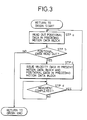
- FIG. 3 shows a subroutine which is programmed in a computer for carrying out a method of the present invention.
- a command is issued in a step a to read out the positional data in a motion data block preceding the finally executed motion data block, i.e., the motion data block corresponding to the present position of the moving component. Then, a step b ascertains whether the positional data has been read in the step a or not. If the positional data has been read, then the velocity data in the motion data block corresponding to the present position of the moving component and the positional data in the preceding motion data block are issued in a step c .
- a step d ascertains whether the movement of the moving component based on the velocity data and the positional data that have been issued in the step c has been completed or not. If the movement of the moving component has been completed, then the processing returns to the step a and executes the above steps. If not completed, then the step d is repeated until the movement of the moving component is completed. If no positional data has been read out in the step b , then the entire process of returning the moving component to the original point is finished.
- the robot control method according to the present invention is essentially effected according to the above procedure.
- a process of returning a moving component of a robot from the motion data block 4 (FIG. 2) to the original point according to the robot control method of the invention, using the motion data blocks of FIG. 2, will be described below.
- the step a For returning the moving component to the original point A after the moving component has been moved to the position D based on the motion data blocks shown in FIG. 2, the step a is executed first, i.e., a command is issued to read out the positional data in the preceding motion data block which is the motion data block 3. Then, the step b determines whether the positional data has been read out or not as a result of the execution of the step a . Since the positional data P C has been read out in the step a , the step b is followed by the step c which issues the velocity data V D in the motion data block 4 and the positional data P C in the motion data block 3. As a result, the moving component is moved from the position D to the position C based on the velocity data V D .
- step a When the movement is completed, then the processing goes from the step d back to the step a .
- the step a then reads out the positional data P B in the motion data block 2.
- the processing goes from the step a via the step b to the step c which issues the velocity data V C in the motion data block 3 and the positional data P B in the motion data block 2.
- the moving component is now moved from the position C to the position B based on the velocity data V C . If the step d determines that the movement has been completed, then the step a is executed again.
- the positional data P A in the motion data block a is read out in the step a , which is followed successively by the steps b and c .
- the step c issues the velocity data V B in the motion data block 2 and the positional data P A in the motion data block l.
- the moving component now returns from the position B to the original point A based on the velocity data V B .
- the step d is then followed by the successive steps a and b . Since no motion data block is present before the motion data block l, the result of the decision in the step b is NO, and the processing of returning to the original point is finished.
- the velocities at which the moving component returns to the origin are successively established by issuing the velocity data corresponding to the respective movement zones, it is possible to uniformize the velocities in the respective movement zones during returning movement to the origin.
- the robot control method of the present invention is also quite simple, not requiring the conventional manual complex operation, since the method can automatically be effected by a simple program subroutine.
Landscapes
- Engineering & Computer Science (AREA)
- Computing Systems (AREA)
- Theoretical Computer Science (AREA)
- Human Computer Interaction (AREA)
- Manufacturing & Machinery (AREA)
- Physics & Mathematics (AREA)
- General Physics & Mathematics (AREA)
- Automation & Control Theory (AREA)
- Numerical Control (AREA)
- Manipulator (AREA)
Applications Claiming Priority (2)
| Application Number | Priority Date | Filing Date | Title |
|---|---|---|---|
| JP60263226A JPS62123504A (ja) | 1985-11-22 | 1985-11-22 | ロボツトの制御方法 |
| JP263226/85 | 1985-11-22 |
Publications (3)
| Publication Number | Publication Date |
|---|---|
| EP0227304A2 true EP0227304A2 (fr) | 1987-07-01 |
| EP0227304A3 EP0227304A3 (en) | 1988-11-23 |
| EP0227304B1 EP0227304B1 (fr) | 1993-03-10 |
Family
ID=17386529
Family Applications (1)
| Application Number | Title | Priority Date | Filing Date |
|---|---|---|---|
| EP86309104A Expired - Lifetime EP0227304B1 (fr) | 1985-11-22 | 1986-11-20 | Méthode pour commander un robot |
Country Status (4)
| Country | Link |
|---|---|
| US (1) | US4912383A (fr) |
| EP (1) | EP0227304B1 (fr) |
| JP (1) | JPS62123504A (fr) |
| DE (1) | DE3687960T2 (fr) |
Cited By (2)
| Publication number | Priority date | Publication date | Assignee | Title |
|---|---|---|---|---|
| WO1992002871A1 (fr) * | 1990-08-08 | 1992-02-20 | Digital Arts Film & Television Pty. Ltd. | Systeme de commande de mouvement pour la technique cinematographique |
| WO2013013686A1 (fr) * | 2011-07-27 | 2013-01-31 | Abb Technology Ag | Système de commande d'un robot |
Families Citing this family (8)
| Publication number | Priority date | Publication date | Assignee | Title |
|---|---|---|---|---|
| KR0160992B1 (ko) * | 1992-08-13 | 1998-12-15 | 윤종룡 | 로보트의 위치결정제어방법 |
| JP3804994B2 (ja) * | 1994-07-15 | 2006-08-02 | ファナック株式会社 | ロボットの教示方法 |
| ITMI20012798A1 (it) * | 2001-12-24 | 2003-06-24 | Lucio Vaccani | Procedimento e dispositivo di generazione di onde particolarmente peril controllo degli assi per macchine utensili e simili |
| JP2005219133A (ja) * | 2004-02-03 | 2005-08-18 | Fanuc Ltd | ロボット用サーボモータ制御装置およびロボット |
| JP4027350B2 (ja) * | 2004-06-29 | 2007-12-26 | ファナック株式会社 | ロボットの待機位置復帰プログラム作成装置 |
| JP5139230B2 (ja) * | 2008-10-06 | 2013-02-06 | オークマ株式会社 | 数値制御装置における衝突防止装置 |
| US8340820B2 (en) * | 2010-02-26 | 2012-12-25 | Agilent Technologies, Inc. | Robot arm and method of controlling robot arm to avoid collisions |
| JP6939104B2 (ja) * | 2017-06-09 | 2021-09-22 | セイコーエプソン株式会社 | 制御装置、ロボットシステムおよびロボット制御方法 |
Family Cites Families (10)
| Publication number | Priority date | Publication date | Assignee | Title |
|---|---|---|---|---|
| NO115175B (fr) * | 1966-11-29 | 1968-08-19 | Kongsberg Vapenfab As | |
| US3889105A (en) * | 1974-08-20 | 1975-06-10 | Gen Electric | Automatic back up of a numerical control |
| SE443531B (sv) * | 1978-11-27 | 1986-03-03 | Asea Ab | Industrirobotutrustning |
| EP0075792B1 (fr) * | 1981-09-24 | 1987-08-26 | Hitachi, Ltd. | Système de commande pour la main d'un robot |
| JPS5935205A (ja) * | 1982-08-23 | 1984-02-25 | Fanuc Ltd | Ncプログラミング機能を有する装置 |
| JPS59153207A (ja) * | 1983-02-21 | 1984-09-01 | Mitsubishi Electric Corp | ロボツトの制御装置 |
| JPS59212911A (ja) * | 1983-05-18 | 1984-12-01 | Fanuc Ltd | Nc加工デ−タ作成方法における角度デ−タ判別方法 |
| GB2146796B (en) * | 1983-08-31 | 1986-12-17 | Mitsubishi Electric Corp | Method for controlling an industrial robot to perform weaving-like motion and apparatus for practising the same |
| GB2147121B (en) * | 1983-09-23 | 1987-05-07 | Japax Inc | A method of an apparatus for controlling an electroerosion process |
| JPH0619657B2 (ja) * | 1983-12-09 | 1994-03-16 | 株式会社日立製作所 | ロボツトの制御方法および装置 |
-
1985
- 1985-11-22 JP JP60263226A patent/JPS62123504A/ja active Pending
-
1986
- 1986-11-20 US US06/933,043 patent/US4912383A/en not_active Expired - Fee Related
- 1986-11-20 DE DE86309104T patent/DE3687960T2/de not_active Expired - Fee Related
- 1986-11-20 EP EP86309104A patent/EP0227304B1/fr not_active Expired - Lifetime
Cited By (6)
| Publication number | Priority date | Publication date | Assignee | Title |
|---|---|---|---|---|
| WO1992002871A1 (fr) * | 1990-08-08 | 1992-02-20 | Digital Arts Film & Television Pty. Ltd. | Systeme de commande de mouvement pour la technique cinematographique |
| AU661825B2 (en) * | 1990-08-08 | 1995-08-10 | Digital Arts Film & Television Pty Ltd | Motion control system for cinematography |
| US5457370A (en) * | 1990-08-08 | 1995-10-10 | Digital Arts Film And Television Pty Ltd | Motion control system for cinematography |
| WO2013013686A1 (fr) * | 2011-07-27 | 2013-01-31 | Abb Technology Ag | Système de commande d'un robot |
| CN103718120A (zh) * | 2011-07-27 | 2014-04-09 | Abb技术有限公司 | 用于命令机器人的系统 |
| US9254567B2 (en) | 2011-07-27 | 2016-02-09 | Abb Technology Ag | System for commanding a robot |
Also Published As
| Publication number | Publication date |
|---|---|
| DE3687960T2 (de) | 1993-10-28 |
| JPS62123504A (ja) | 1987-06-04 |
| EP0227304A3 (en) | 1988-11-23 |
| US4912383A (en) | 1990-03-27 |
| EP0227304B1 (fr) | 1993-03-10 |
| DE3687960D1 (de) | 1993-04-15 |
Similar Documents
| Publication | Publication Date | Title |
|---|---|---|
| US4482968A (en) | Method and apparatus for robot control | |
| US5254923A (en) | Industrial robot synchronous control method and apparatus | |
| EP0022372B1 (fr) | Système de commande numérique comprenant une machine-outil et un robot | |
| US5003237A (en) | Method of correcting and playing back positional instruction data in a robot | |
| US4912383A (en) | Method of controlling a robot | |
| EP0077177B1 (fr) | Méthode et dispositif pour la commande numérique | |
| EP0785490B1 (fr) | Procede de commande d'un robot | |
| US5444343A (en) | Method and apparatus for numerically controlling industrial machine | |
| US5057995A (en) | Robot control apparatus | |
| EP0086848A1 (fr) | Methode d'enseignement d'operations a un robot | |
| EP0377939B1 (fr) | Système de commande de robot pour commander un ensemble de robots industriels | |
| JPS62251901A (ja) | 多軸ロボツトの経路制御装置 | |
| JPH0797290B2 (ja) | 複数ア−ムの制御装置 | |
| JPH02254503A (ja) | オフライン教示システムの実行データ伝送方式 | |
| JP2000061870A (ja) | ロボットの原点復帰方法 | |
| EP0083502A1 (fr) | Méthode de commande de robot et appareil | |
| JP2577003B2 (ja) | ロボットの制御方法 | |
| CN116529035A (zh) | 数值控制装置以及数值控制系统 | |
| JPH06122025A (ja) | プレスブレーキロボットシステムのワーク曲げ追従方法 | |
| EP0094214B1 (fr) | Commande de robot industriel | |
| JP3191341B2 (ja) | ロボット制御装置 | |
| CN112643647B (zh) | 机器人控制装置以及机器人控制方法 | |
| JPH06270082A (ja) | 補軸を有するロボットの制御方法 | |
| JPS61193206A (ja) | ロボツトの教示方法 | |
| JPS621005A (ja) | ロボツトの教示方法 |
Legal Events
| Date | Code | Title | Description |
|---|---|---|---|
| PUAI | Public reference made under article 153(3) epc to a published international application that has entered the european phase |
Free format text: ORIGINAL CODE: 0009012 |
|
| AK | Designated contracting states |
Kind code of ref document: A2 Designated state(s): DE FR GB IT |
|
| PUAL | Search report despatched |
Free format text: ORIGINAL CODE: 0009013 |
|
| RHK1 | Main classification (correction) |
Ipc: G05B 19/18 |
|
| AK | Designated contracting states |
Kind code of ref document: A3 Designated state(s): DE FR GB IT |
|
| 17P | Request for examination filed |
Effective date: 19890505 |
|
| 17Q | First examination report despatched |
Effective date: 19910524 |
|
| RAP1 | Party data changed (applicant data changed or rights of an application transferred) |
Owner name: TOSHIBA KIKAI KABUSHIKI KAISHA |
|
| ITF | It: translation for a ep patent filed | ||
| GRAA | (expected) grant |
Free format text: ORIGINAL CODE: 0009210 |
|
| AK | Designated contracting states |
Kind code of ref document: B1 Designated state(s): DE FR GB IT |
|
| REF | Corresponds to: |
Ref document number: 3687960 Country of ref document: DE Date of ref document: 19930415 |
|
| ET | Fr: translation filed | ||
| ITTA | It: last paid annual fee | ||
| PLBE | No opposition filed within time limit |
Free format text: ORIGINAL CODE: 0009261 |
|
| STAA | Information on the status of an ep patent application or granted ep patent |
Free format text: STATUS: NO OPPOSITION FILED WITHIN TIME LIMIT |
|
| 26N | No opposition filed | ||
| PGFP | Annual fee paid to national office [announced via postgrant information from national office to epo] |
Ref country code: GB Payment date: 19941019 Year of fee payment: 9 |
|
| PGFP | Annual fee paid to national office [announced via postgrant information from national office to epo] |
Ref country code: FR Payment date: 19941028 Year of fee payment: 9 |
|
| PGFP | Annual fee paid to national office [announced via postgrant information from national office to epo] |
Ref country code: DE Payment date: 19941116 Year of fee payment: 9 |
|
| PG25 | Lapsed in a contracting state [announced via postgrant information from national office to epo] |
Ref country code: GB Effective date: 19951120 |
|
| GBPC | Gb: european patent ceased through non-payment of renewal fee |
Effective date: 19951120 |
|
| PG25 | Lapsed in a contracting state [announced via postgrant information from national office to epo] |
Ref country code: FR Effective date: 19960731 |
|
| PG25 | Lapsed in a contracting state [announced via postgrant information from national office to epo] |
Ref country code: DE Effective date: 19960801 |
|
| REG | Reference to a national code |
Ref country code: FR Ref legal event code: ST |
|
| PG25 | Lapsed in a contracting state [announced via postgrant information from national office to epo] |
Ref country code: IT Free format text: LAPSE BECAUSE OF NON-PAYMENT OF DUE FEES;WARNING: LAPSES OF ITALIAN PATENTS WITH EFFECTIVE DATE BEFORE 2007 MAY HAVE OCCURRED AT ANY TIME BEFORE 2007. THE CORRECT EFFECTIVE DATE MAY BE DIFFERENT FROM THE ONE RECORDED. Effective date: 20051120 |