EP0227350A2 - Surveillance de conducteurs dans des câbles - Google Patents
Surveillance de conducteurs dans des câbles Download PDFInfo
- Publication number
- EP0227350A2 EP0227350A2 EP86309429A EP86309429A EP0227350A2 EP 0227350 A2 EP0227350 A2 EP 0227350A2 EP 86309429 A EP86309429 A EP 86309429A EP 86309429 A EP86309429 A EP 86309429A EP 0227350 A2 EP0227350 A2 EP 0227350A2
- Authority
- EP
- European Patent Office
- Prior art keywords
- conductors
- photon
- ribbon cable
- output
- cable
- Prior art date
- Legal status (The legal status is an assumption and is not a legal conclusion. Google has not performed a legal analysis and makes no representation as to the accuracy of the status listed.)
- Withdrawn
Links
Images

Classifications
-
- G—PHYSICS
- G01—MEASURING; TESTING
- G01B—MEASURING LENGTH, THICKNESS OR SIMILAR LINEAR DIMENSIONS; MEASURING ANGLES; MEASURING AREAS; MEASURING IRREGULARITIES OF SURFACES OR CONTOURS
- G01B15/00—Measuring arrangements characterised by the use of electromagnetic waves or particle radiation, e.g. by the use of microwaves, X-rays, gamma rays or electrons
Definitions
- This invention relates to the determination of the configuration of the conductors in a ribbon cable.
- 'configuration of the conductors' is herein meant to include the position of conductors within the ribbon cable, the size of the conductors, the number of conductors present, or the spacing between two or more conductors of the cable.
- Ribbon cable consists of a plurality of electric conductors contained within a sheath of electrically insulating material. Often connectors are terminated on to ribbon cable using insulation piercing contacts, which require the spacing between the conductors of the ribbon cable to be consistent. This is especially so where the contacts are inserted automatically.
- Some idea of the spacing of the conductors can be obtained by measuring the thickness of the ribbon cable with width measuring means.
- One known optical system measures the profile of the cable and can be used to estimate the positions of the conductors. This invention provides an improved technique for determining the configuration of conductors in a ribbon cable.
- a method of determining the configuration of the conductors in a ribbon cable comprises illuminating one or more of the conductors with a beam of photons from a photon source; detecting the photon beam emerging from the ribbon cable at least from the one or more conductors with one or more photon detectors; and calculating, from the output of the one or more photon detectors, the configuration of the conductors of the ribbon cable with electronic processing means.
- photons is hereby meant to include all types of penetrating radiation such as gamma rays and low energy x-rays which are capable of passing through the insulating sheath of the cable, and to a lesser extent, the conductors of the cable.
- the term may conceivably also include a light beam of sufficient intensity to pass through the insulating sheath of the cable, at least to a discernable extent.
- the photon beam is preferably detected emerging from at least two of the conductors and continuously therebetween.
- This may preferably be by means of a photon-responsive screen, such as one formed of a fluorescent material.
- Signals from the fluorescent screen may be transferred by means of a fibre optic arrangement to an opto-electronic detector which converts the optical output from the screen into electronic signals for the processing means.
- the signals from the screen may be transferred to the opto-electronic detector by means of a lens arrangement.
- the photon source is adapted to produce a diverging beam of photons to illuminate at least two of the conductors.
- the photon source is adapted to produce a substantially collimated beam of photons which is caused to scan the cable to illuminate at least two of the conductors.
- the photon beam is preferably caused to illuminate the entire width of the ribbon cable, such that all of the conductors contained therein are illuminated.
- the radiation emerging from the cable will be in the form a series of peaks and troughs, the peaks of high transmission through the sheath material between the conductors, and the troughs of low transmission through the conductors themselves.
- the electronic processing means is adapted to calculate, from the output of the one or more photon detectors, the separation between two or more conductors of the cable.
- the electronic processing means determines threshold positions where the output of the one or more photon detectors crosses a predetermined reference level and calculates, by establishing the mean of adjacent threshold positions, the position of the two or more conductors. This threshold detection can be applied to establish the position of each of the conductors in the ribbon cable such that the spacing between any two of the conductors can be determined.
- the electronic processing means samples the output of the one or more photon detectors, determines the gradient between adjacent samples and calculates, by establishing positions where the gradient is substantially zero, the position of the two or more conductors.
- the electronic processing means is provided with a read only memory, in which is stored data indicative of the output of the one or more photon detectors on detecting the photon beam emerging from the ribbon cable at one of the conductors, the electronic processing means sampling the output from the one or more photon detectors and comparing the samples with the data stored in the read only memory to calculate the position of the two or more conductors.
- the electronic processing means is a microprocessor.
- the ribbon cable may conceivably be moving relative to the photon source and the one or more photon detectors. This enables the separation of the conductors to be determined on-line, such that cable being manufactured may be monitored. This allows corrective action to be carried out promptly and effectively should the monitoring establish that unacceptable cable is being produced.
- the photon source is preferably a radioactive source producing gamma rays.
- the source may be a low intensity x-ray generator, preferably operating from a DC potential.
- apparatus for determining the configuration of conductors in a ribbon cable comprises a photon source for producing a beam of photons adapted to be caused to illuminate one or more of the conductors; one or more photon detectors positioned on the opposite side of the ribbon cable to the photon source and capable of detecting the photon beam emerging from the ribbon cable at least from the one or more conductors; and electronic processing means connected to the one or more photon connectors and adapted to calculate, from the output of the one or more photon detectors, the configuration of the conductors of the ribbon cable.
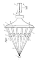
- a photon source 1 such as a low intensity x-ray generator, produces a diverging beam of radiation shown generally at 2.
- the beam illuminates a ribbon cable 3 comprising six conductors 4 in a sheath 5 of insulating plastics material. Radiation emerging from the cable 3 impinges on a fluorescent screen, optical signals from which are transferred by means of a fibre optic reducer 7 to an opto-electronic converter 8.
- the converter 8 converts optical signals from the fibre optic reducer 7 into electronic signals which are fed to a microprocesor 9 by means of a line 10.
- the microprocessor 9 therefore receives from the opto-electronic converter 8 a waveform consisting of a series of peaks and troughs as shown in Figure 2.
- the microprocessor converts the waveform into digital form and establishes threshold positions 16 where the waveform signal crosses a predetermined reference level 15. By calculating the mean of adjacent threshold positions 16 the microprocessor can estimate the location 17 of the centre of the conductors 4.
- the microprocessor 9 compares the digital readings with data stored in Read only memory 20.
- the data stored in the memory 20 includes values for the output of the screen 6 where the beam passes through both the sheath 5 and conductors 4. By comparing the readings with the data in the Read only memory 20, the microprocessor 9 can estimate the location of the conductors 4.
- the microprocessor 9 is able to calculate the spacing between adjacent conductors and, if desired, the spacing between any particular conductor and all of the others in the ribbon cable. In this way a conductor which is incorrectly positioned with respect to the other conductors within the cable can be identified.
- Ribbon cable 3 is moved past the source 1, for example on a cable production line, to enable the continuous monitoring of the spacing of the conductors in the cable.
- the microprocessor can be made to activate an alarm, alerting an operator to the fact that unacceptable cable is being produced.
Landscapes
- Physics & Mathematics (AREA)
- Electromagnetism (AREA)
- General Physics & Mathematics (AREA)
- Analysing Materials By The Use Of Radiation (AREA)
- Length-Measuring Devices Using Wave Or Particle Radiation (AREA)
- Measurement Of Radiation (AREA)
Applications Claiming Priority (2)
| Application Number | Priority Date | Filing Date | Title |
|---|---|---|---|
| GB858529722A GB8529722D0 (en) | 1985-12-03 | 1985-12-03 | Monitoring conductors in cable |
| GB8529722 | 1985-12-03 |
Publications (2)
| Publication Number | Publication Date |
|---|---|
| EP0227350A2 true EP0227350A2 (fr) | 1987-07-01 |
| EP0227350A3 EP0227350A3 (fr) | 1989-06-14 |
Family
ID=10589160
Family Applications (1)
| Application Number | Title | Priority Date | Filing Date |
|---|---|---|---|
| EP86309429A Withdrawn EP0227350A3 (fr) | 1985-12-03 | 1986-12-03 | Surveillance de conducteurs dans des câbles |
Country Status (2)
| Country | Link |
|---|---|
| EP (1) | EP0227350A3 (fr) |
| GB (2) | GB8529722D0 (fr) |
Cited By (2)
| Publication number | Priority date | Publication date | Assignee | Title |
|---|---|---|---|---|
| EP1450127A2 (fr) | 2003-02-21 | 2004-08-25 | Sikora Ag | Procédé et dispositif pour mesurer l'épaisseur de l'isolation d'un câble plat |
| US7191091B2 (en) | 2004-12-01 | 2007-03-13 | 3M Innovative Properties Company | Advanced cable metrology system |
Family Cites Families (8)
| Publication number | Priority date | Publication date | Assignee | Title |
|---|---|---|---|---|
| GB818105A (en) * | 1957-02-04 | 1959-08-12 | Isotope Developments Ltd | Improvements in or relating to gauges |
| GB847129A (en) * | 1957-07-11 | 1960-09-07 | Atomic Energy Authority Uk | Improvements in or relating to methods and apparatus for determining the eccentricity of two normally concentric cylinders of different materials |
| GB1225013A (en) * | 1967-12-13 | 1971-03-17 | British Insulated Callenders | Improvements in or relating to methods of and apparatus for testing electric cables |
| US3796874A (en) * | 1971-08-18 | 1974-03-12 | Westinghouse Electric Corp | Non-destructive eccentricity and insulation thickness measurement system |
| US3999067A (en) * | 1975-10-14 | 1976-12-21 | The United States Of America As Represented By The United States Energy Research And Development Administration | High speed radiation scanning technique for simultaneously determining the pitch and eccentricity of an encased oil |
| DE2608841A1 (de) * | 1976-03-04 | 1977-09-08 | Philips Patentverwaltung | Verfahren und vorrichtung zum automatischen ueberpruefen der lage und/oder abmessungen wenigstens eines koerpers |
| GB2132343A (en) * | 1982-12-07 | 1984-07-04 | Bicc Plc | Monitoring an electric cable core |
| JPS60117105A (ja) * | 1983-11-30 | 1985-06-24 | Toshiba Corp | 放射線計測装置 |
-
1985
- 1985-12-03 GB GB858529722A patent/GB8529722D0/en active Pending
-
1986
- 1986-12-03 GB GB08628953A patent/GB2183829A/en not_active Withdrawn
- 1986-12-03 EP EP86309429A patent/EP0227350A3/fr not_active Withdrawn
Cited By (4)
| Publication number | Priority date | Publication date | Assignee | Title |
|---|---|---|---|---|
| EP1450127A2 (fr) | 2003-02-21 | 2004-08-25 | Sikora Ag | Procédé et dispositif pour mesurer l'épaisseur de l'isolation d'un câble plat |
| JP2004251906A (ja) * | 2003-02-21 | 2004-09-09 | Sikora Ag | 導電路領域の平形リボンケーブルの絶縁体厚さの測定方法および装置 |
| EP1450127A3 (fr) * | 2003-02-21 | 2006-05-03 | Sikora Ag | Procédé et dispositif pour mesurer l'épaisseur de l'isolation d'un câble plat |
| US7191091B2 (en) | 2004-12-01 | 2007-03-13 | 3M Innovative Properties Company | Advanced cable metrology system |
Also Published As
| Publication number | Publication date |
|---|---|
| EP0227350A3 (fr) | 1989-06-14 |
| GB8628953D0 (en) | 1987-01-07 |
| GB8529722D0 (en) | 1986-01-08 |
| GB2183829A (en) | 1987-06-10 |
Similar Documents
| Publication | Publication Date | Title |
|---|---|---|
| US4573193A (en) | Individual identification apparatus | |
| EP0599297B1 (fr) | Méthode pour détecter des impurités dans un résine fondue | |
| DE3826067C2 (fr) | ||
| PL343252A1 (en) | Arrangement and method to apply diffusing wave spectroscopy to measure the properties of multi-phase systems, as well as the changes therein | |
| KR900700893A (ko) | 고압 배전반의 장해방지 및 감시시스템 | |
| US4692799A (en) | Automatic inspection system for detecting foreign matter | |
| US4914307A (en) | Optoelectronic device for contactless measurement of the dimensions of objects | |
| FR2749986B1 (fr) | Appareil de detection de defaut d'isolement d'un dispositif branche dans un reseau de distribution ou de transport d'energie electrique et procede de detection correspondant | |
| US5408325A (en) | Apparatus for measuring the profile of a moving object | |
| KR880008481A (ko) | 중성자 방사선량 측정방법 및 장치 | |
| WO1981003698A1 (fr) | Procede et dispositif permettant le controle d'un mouvement | |
| EP0227350A2 (fr) | Surveillance de conducteurs dans des câbles | |
| CA1118893A (fr) | Detecteur pour la determination d'une longueur de marche | |
| ES8407207A1 (es) | Metodo y aparato para el analisis de heterogeneidades en un material transparente | |
| CN108582580A (zh) | 基于近红外技术的塑料在线分拣装置及其分拣方法 | |
| EP0006648B1 (fr) | Procédé et appareil de détection des défauts de forme allongée d'une feuille en mouvement | |
| EP0741276A1 (fr) | Mesure sans contact du déplacement et des changements en dimension des objets allongés comme des filaments | |
| EP0100412A2 (fr) | Dispositif pour l'inspection et la mesure de filaments | |
| US20030076509A1 (en) | Sensor device that provides part quality and profile information | |
| EP0093890B1 (fr) | Appareil pour la détection d'irrégularités à la surface d'un matériau filiforme | |
| RU2070717C1 (ru) | Базисный фотометр | |
| JPH10142164A (ja) | 線条体の表面欠陥検査装置 | |
| GB2223844A (en) | Flame detector | |
| CN208495028U (zh) | 一种基于近红外技术的塑料在线分拣装置 | |
| US5995216A (en) | Pattern inspection apparatus |
Legal Events
| Date | Code | Title | Description |
|---|---|---|---|
| PUAI | Public reference made under article 153(3) epc to a published international application that has entered the european phase |
Free format text: ORIGINAL CODE: 0009012 |
|
| AK | Designated contracting states |
Kind code of ref document: A2 Designated state(s): AT BE CH DE ES FR GR IT LI LU NL SE |
|
| PUAL | Search report despatched |
Free format text: ORIGINAL CODE: 0009013 |
|
| RHK1 | Main classification (correction) |
Ipc: G01B 15/00 |
|
| AK | Designated contracting states |
Kind code of ref document: A3 Designated state(s): AT BE CH DE ES FR GR IT LI LU NL SE |
|
| STAA | Information on the status of an ep patent application or granted ep patent |
Free format text: STATUS: THE APPLICATION IS DEEMED TO BE WITHDRAWN |
|
| 18D | Application deemed to be withdrawn |
Effective date: 19890102 |
|
| RIN1 | Information on inventor provided before grant (corrected) |
Inventor name: BHATTACHARYA, SABYASACHI, DR. Inventor name: SHUTTLEWORTH, ERNEST PAUL |