EP0227376B1 - Dispositif de codage - Google Patents
Dispositif de codage Download PDFInfo
- Publication number
- EP0227376B1 EP0227376B1 EP86309600A EP86309600A EP0227376B1 EP 0227376 B1 EP0227376 B1 EP 0227376B1 EP 86309600 A EP86309600 A EP 86309600A EP 86309600 A EP86309600 A EP 86309600A EP 0227376 B1 EP0227376 B1 EP 0227376B1
- Authority
- EP
- European Patent Office
- Prior art keywords
- rod
- frame
- wheels
- shaft
- coding box
- Prior art date
- Legal status (The legal status is an assumption and is not a legal conclusion. Google has not performed a legal analysis and makes no representation as to the accuracy of the status listed.)
- Expired
Links
- 230000002093 peripheral effect Effects 0.000 claims description 5
- 239000011888 foil Substances 0.000 claims description 3
- 230000004048 modification Effects 0.000 description 4
- 238000012986 modification Methods 0.000 description 4
- 229910001369 Brass Inorganic materials 0.000 description 3
- 239000010951 brass Substances 0.000 description 3
- 229910001209 Low-carbon steel Inorganic materials 0.000 description 2
- 125000006850 spacer group Chemical group 0.000 description 2
- CWYNVVGOOAEACU-UHFFFAOYSA-N Fe2+ Chemical compound [Fe+2] CWYNVVGOOAEACU-UHFFFAOYSA-N 0.000 description 1
- 239000003779 heat-resistant material Substances 0.000 description 1
- 239000000463 material Substances 0.000 description 1
- 239000002184 metal Substances 0.000 description 1
- 239000004810 polytetrafluoroethylene Substances 0.000 description 1
- 229920001343 polytetrafluoroethylene Polymers 0.000 description 1
- 239000000758 substrate Substances 0.000 description 1
- 239000004753 textile Substances 0.000 description 1
Images


Classifications
-
- B—PERFORMING OPERATIONS; TRANSPORTING
- B41—PRINTING; LINING MACHINES; TYPEWRITERS; STAMPS
- B41K—STAMPS; STAMPING OR NUMBERING APPARATUS OR DEVICES
- B41K3/00—Apparatus for stamping articles having integral means for supporting the articles to be stamped
- B41K3/02—Apparatus for stamping articles having integral means for supporting the articles to be stamped with stamping surface located above article-supporting surface
- B41K3/04—Apparatus for stamping articles having integral means for supporting the articles to be stamped with stamping surface located above article-supporting surface and movable at right angles to the surface to be stamped
- B41K3/08—Apparatus for stamping articles having integral means for supporting the articles to be stamped with stamping surface located above article-supporting surface and movable at right angles to the surface to be stamped having adjustable type-carrying wheels
Definitions
- the invention relates to coding boxes for hot foil printing machines. Such machines are generally used for "use by” dating or stamping other indicia onto packages, particularly to packages containing perishables.
- the coding box is adjustable to vary the indicia stamped.
- Coding boxes comprise a frame for bolting onto a printing machine.
- One previously known kind of box comprises also a number of print wheels, each having a number of outward-facing peripheral flats, and each flat bearing an individual digit, letter or character.
- the print wheels are all rotable about a single axis with respect to the frame, and provided with spring-loaded centring means to ensure that the printing is even.
- One of the problems is that in operation the vibration eventually tends to wear the mechanism, so that the wheels spin loose and crash, the printing is uneven and the substrate package may be damaged.
- US-A-3916783 discloses apparatus for printing on a continuous strip of textile material, in which the printing unit may comprise a plurality of discs each carrying a plurality of circumferentially spaced raised characters and rotatably mounted on a spindle. A locking spindle engages grooves between the raised characters but may be removed to allow rotation of the individual discs.
- a coding box comprises a frame for attaching to the printing machine, a number of print wheels rotatable about a shaft with respect to the frame, each print wheel having a number of outward-facing peripheral flats bearing indicia; a first rod extending parallel to the shaft and radially offset therefrom, the rod being securable to the frame in a set position to set the wheels in desired orientations with respect to the frame; characterized by each wheel having a through-hole corresponding to each flat, said through-holes being located and adapted for the said first rod to pass therethrough when being in the said set position, the said first rod passing through a first through-hole in the frame and being axially movable therethrough between the said set position and a retracted position in which the said wheels are free to rotate about the said shaft; means for locking the first rod in its set position; a second rod fast with respect to and parallel to the first rod and having an enlarged distal end; and a second through-hole in the frame radially offset from the shaft and
- the first and second rods are preferably both fast in a handle by which they may be withdrawn from the wheels to permit rotation of the wheels, and thus variation of the indicia to be stamped.
- the handle is preferably of heat-resistant material such as PTFE.
- the locking means may comprise a magnetic part of the handle which is attracted towards the frame (which is generally of ferrous metal).
- the block is preferably provided with one or more spaces between adjacent print wheels to allow a little flexibility and facilitate the mounting of the wheels in the frame.
- the wheels and spacers are usually made of brass because of its machinability.
- the first rod passing through the holes in the printing wheels provides positive engagement for aligning the faces on the wheels, hence ensuring even printing, without the involvement of any spring.
- the locking means reduces noise from relative movement between parts in use, and hence wear.
- a coding box according to the invention may be constructed so as to have no removable parts; this makes for safety and reliability.
- the wheels may for example have ten flats each bearing a single digit from 0 to 9. Alternatively, the wheels may have eleven flats so that a blank may be included. Another possibility is for the wheels to have twelve flats and be made wide enough for each flat to bear the name of a month or the whole of an abbreviation therefor.
- the magnet should be heat resistant, and may be small in relation to the other components of the coding box, and may be made to adhere to a part of the handle adjacent the frame.
- the magnet itself is preferably protected against damage through impact or wear by being mounted in a mild steel cup which itself adheres in a recess to the handle.
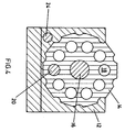
- the coding box comprises a mild steel frame 12 provided with screw holes (not shown) for fixing in a hot foil printing machine.
- a number of brass print wheels 14 are rotatable about a shaft 16 ( Figure 2b) secured by a screw 17 with respect to the frame 12.
- Each print wheel 14 has a number of outward-facing peripheral flats, which are particularly apparent in Figure 4, bearing indicia, i.e. a digit or letter in mirror image for printing on a package.
- Figure 4 also shows how each print wheel 14 has a number of through-holes 18 parallel to the shaft 16.
- Each hole 18 corresponds to one of the peripheral flats on the print wheel 14.
- Each hole 18 as shown has a diameter coincident with a radius of the print wheel 14 normal to the corresponding flat, but this is not essential as each hole 18 could be off-set from its corresponding flat by a given amount and still enable the print wheels to be set in desired orientations.
- a (first) rod 20 is passable through the holes 18 for setting the print wheels 14 with respect to the frame 12.
- a small magnet which does not itself appear in the drawings adheres inside a cup 22 which itself adheres in a recess in an end face of a handle 26 of the coding box.
- the magnet provides means for locking the rod 20 in a set position through its attraction to an end of the shaft 16.
- a (second) rod 24 projects from the handle 26, and so is fast with respect to the first rod 20 to which it is parallel.
- the rod 24 has an enlarged distal end 24a for engagement with a hole in the frame 12 to prevent complete removal of the first rod 20 from the frame 12.
- a number of brass spacers 28 are provided between adjacent print wheels 14.
- the coding box is moved from the closed or operative position shown in Figure 1 to the open or adjustment position shown in Figure 3 by pulling the handle 26 to the left.
- the rods 20, 24 are thus withdrawn from the frame 12 as far as allowed by the engagement between the enlarged end 24a of the second rod 24 with a hole in the frame 12 as shown in Figure 3.
- a certain amount of slack in the holes 18 around the tip (not shown) of the first rod 20 in practice allows the rod 20 to be reintroduced into the holes 18 when not perfectly aligned, and in so doing to render the faces co-planar for even printing.
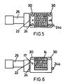
- fitters 30 have been screwed to the top faces of the frame 12.
- the fitters 30 carry extra information, in Figure 5 No. and A, for printing in every case at either end of the indicia exposed on the wheels 14.
- the fitters 30 are of a thickness such as to bring the extra information into the same plane as the indicia exposed on the wheels 14.
- fitters 30 marked BEST BEFORE and 26g e extend along the coding box so that the extra information is printed in every case above and below the indicia exposed on the wheels 14.
- the fitters extend down the outside of the coding box for strength.
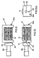
- the third modification of Figures 9, 10 and 10a has the frame extending along a side of the coding box (the upper side in Figure 9) and not along the base as hitherto. This makes the coding box shallower than in the preceding embodiments which is an advantage in some printing machines.
- the wheels 14 in this modification carry indicia showing a sell by date, characters for identification purposes, and a price.
Landscapes
- Details Of Rigid Or Semi-Rigid Containers (AREA)
- Auxiliary Devices For And Details Of Packaging Control (AREA)
Claims (3)
- Dispositif de codage pour machine d'impression à feuille chaude, qui comprend un support (12) pour sa fixation à la machine d'impression, un certain nombre de roulettes d'impression (14) rotatives autour d'un axe (16) par rapport au support (12), chaque roulette d'impression (14) ayant un certain nombre de facettes périphériques tournées vers l'extérieur et portant des indices ; une première tige (20) s'étendant parallèlement à l'axe (16) et décalée radialement par rapport à celui-ci, la tige 20 pouvant être fixée au support (12) dans une position choisie pour immobiliser les roulettes (14) dans l'orientation voulue par rapport au support ;
caractérisé en ce que chaque roulette (14) présente un trou traversant (18) correspondant à chaque facette, lesdits trous traversants (18) étant positionnés et adaptés au passage de ladite première tige lorsqu'ils sont dans ladite position choisie, ladite première tige (20) passant au travers d'un premier trou traversant dans le support (12) et étant axialement mobile au travers de celui-ci entre ladite position choisie et une position rétractée dans laquelle lesdites roulettes (14) sont libres de tourner autour dudit axe (16) ; des moyens pour verrouiller ladite première tige (20) dans sa position choisie ; une seconde tige (24) solidarisée à ladite première tige (20) et parallèle à celle-ci et ayant une extrémité distale agrandie (24a) ; et un second trou traversant dans le support (12) décalé radialement par rapport à l'axe et adapté et positionné pour permettre à ladite seconde tige d'être déplaçable axialement au travers dudit trou et pour venir en prise avec ladite extrémité distale agrandie (24) pour empêcher l'enlèvement total de la première tige (20) du support (12) et pour définir sa position rétractée. - Dispositif de codage selon la revendication 1, dans lequel les première et seconde tiges (20,24) sont toutes deux solidarisées à une poignée au moyen de laquelle elles peuvent être extraites des roulettes (14) pour permettre la rotation desdites roulettes (14) et donc pour faire varier les indices à timbrer.
- Dispositif de codage selon la revendication 1 ou la revendication 2, dans lequel les moyens de verrouillage sont constitués par un aimant qui est attiré en direction du support.
Applications Claiming Priority (2)
| Application Number | Priority Date | Filing Date | Title |
|---|---|---|---|
| GB8530934 | 1985-12-16 | ||
| GB858530934A GB8530934D0 (en) | 1985-12-16 | 1985-12-16 | Coding boxes |
Publications (3)
| Publication Number | Publication Date |
|---|---|
| EP0227376A2 EP0227376A2 (fr) | 1987-07-01 |
| EP0227376A3 EP0227376A3 (en) | 1988-09-07 |
| EP0227376B1 true EP0227376B1 (fr) | 1992-09-23 |
Family
ID=10589825
Family Applications (1)
| Application Number | Title | Priority Date | Filing Date |
|---|---|---|---|
| EP86309600A Expired EP0227376B1 (fr) | 1985-12-16 | 1986-12-10 | Dispositif de codage |
Country Status (4)
| Country | Link |
|---|---|
| US (1) | US4719853A (fr) |
| EP (1) | EP0227376B1 (fr) |
| DE (1) | DE3686809T2 (fr) |
| GB (1) | GB8530934D0 (fr) |
Families Citing this family (10)
| Publication number | Priority date | Publication date | Assignee | Title |
|---|---|---|---|---|
| US4967654A (en) * | 1989-07-10 | 1990-11-06 | Amp Incorporated | Print head setting apparatus |
| DE4403058C1 (de) * | 1994-02-02 | 1995-02-02 | Eoc Normalien Gmbh & Co Kg | Markiereinsatz für ein Spritzgießwerkzeug |
| GB0309616D0 (en) | 2003-04-28 | 2003-06-04 | Angiomed Gmbh & Co | Loading and delivery of self-expanding stents |
| GB0810749D0 (en) | 2008-06-11 | 2008-07-16 | Angiomed Ag | Catherter delivery device |
| US9750625B2 (en) | 2008-06-11 | 2017-09-05 | C.R. Bard, Inc. | Catheter delivery device |
| AU323511S (en) * | 2008-10-17 | 2009-01-09 | A R C Strang Australia Pty Ltd | Wheel spacer |
| GB0901496D0 (en) | 2009-01-29 | 2009-03-11 | Angiomed Ag | Delivery device for delivering a stent device |
| GB0909319D0 (en) | 2009-05-29 | 2009-07-15 | Angiomed Ag | Transluminal delivery system |
| CN106079938B (zh) * | 2016-06-20 | 2018-08-17 | 苏州全新机械配件有限公司 | 一种简易转动打码装置 |
| CN107791704A (zh) * | 2017-11-06 | 2018-03-13 | 于浩 | 一种锻件热打钢印可调节的磨具 |
Family Cites Families (12)
| Publication number | Priority date | Publication date | Assignee | Title |
|---|---|---|---|---|
| US18249A (en) * | 1857-09-22 | robertson | ||
| FR339437A (fr) * | 1903-01-12 | 1904-06-09 | Frederic De Coppet | Timbreur articulé |
| US848887A (en) * | 1904-07-08 | 1907-04-02 | James Thomas Earle | Automatic identification-stamp. |
| US988242A (en) * | 1909-07-22 | 1911-03-28 | Joseph Blitz | Dating-stamp. |
| FR497756A (fr) * | 1913-12-12 | 1919-12-17 | Frederic De Coppet | Timbre articulé |
| US1289539A (en) * | 1918-04-08 | 1918-12-31 | Timoty B Powers | Multiple-stamp device. |
| US1446013A (en) * | 1921-11-02 | 1923-02-20 | Joseph L Lawrence | Ticket dater |
| FR673790A (fr) * | 1929-02-23 | 1930-01-20 | Timbres dateurs à ressorts | |
| US2506729A (en) * | 1947-11-29 | 1950-05-09 | P M Stamping Device Company Lt | Stamping device |
| US3916783A (en) * | 1972-09-13 | 1975-11-04 | Texmark Inc | Automatic sequential textile marking machine |
| US4228736A (en) * | 1978-07-28 | 1980-10-21 | Griffiths John B | Printing apparatus |
| US4453468A (en) * | 1982-12-29 | 1984-06-12 | Shenoha James L | Heat conducting magnetic type holder for imprinters |
-
1985
- 1985-12-16 GB GB858530934A patent/GB8530934D0/en active Pending
-
1986
- 1986-12-08 US US06/938,972 patent/US4719853A/en not_active Expired - Fee Related
- 1986-12-10 EP EP86309600A patent/EP0227376B1/fr not_active Expired
- 1986-12-10 DE DE8686309600T patent/DE3686809T2/de not_active Expired - Fee Related
Also Published As
| Publication number | Publication date |
|---|---|
| EP0227376A3 (en) | 1988-09-07 |
| EP0227376A2 (fr) | 1987-07-01 |
| US4719853A (en) | 1988-01-19 |
| GB8530934D0 (en) | 1986-01-29 |
| DE3686809T2 (de) | 1993-02-25 |
| DE3686809D1 (de) | 1992-10-29 |
Similar Documents
| Publication | Publication Date | Title |
|---|---|---|
| EP0227376B1 (fr) | Dispositif de codage | |
| DE69707138T2 (de) | Farbbandkassettenbehälter für thermischen übertragungsdruck | |
| EP3196037B1 (fr) | Imprimante servant à imprimer des objets et cassette de ruban encreur à utiliser dans une imprimante | |
| DE3506086A1 (de) | Uebertragungselementanordnung | |
| EP2255207B1 (fr) | Systeme de mesure angulaire et procede de fabrication d'un systeme de mesure angulaire | |
| DE2932426C2 (de) | Einrichtung für eine Wahldruckwalze | |
| EP0221555B1 (fr) | Ensemble boîtier-couvercle pour machine à affranchir | |
| WO2005072963A1 (fr) | Element de securite a couche magnetique partielle | |
| US4049110A (en) | Print wheel mounting assembly | |
| EP0221557A2 (fr) | Machine d'affranchissement universelle modulaire | |
| US3693545A (en) | Coaxial type drums with apertures for changeable type segments | |
| US4431911A (en) | Cash replacement system including an encoded card and card acceptor | |
| GB2243580A (en) | Verifying print position setting of marking elements | |
| US5005477A (en) | Double truck printing registration system for a rotary printing press | |
| EP0221556B1 (fr) | Module de moteur pas à pas pour machine à affranchir | |
| US4389564A (en) | Indexing mechanism for card acceptor | |
| US4656341A (en) | Postage meter printhead assembly | |
| DE69403870T2 (de) | Druckplattenkassette für eine Frankiermaschine | |
| US4852478A (en) | Apparatus for imprinting a document with secure, machine readable information | |
| US2927528A (en) | Code printing machine | |
| EP0269816A2 (fr) | Support de plaque cylindrique pour presse lithographique à support de plaque amovible, en particulier pour l'impression de corps cylindriques et analogues | |
| KR890001161B1 (ko) | 다면 인쇄 윤전기 | |
| EP0742942A1 (fr) | Procede d'identification de supports d'informations a lecture optique, se presentant sous forme de disques | |
| US4726215A (en) | Adjustable diameter stamp | |
| DE270411C (fr) |
Legal Events
| Date | Code | Title | Description |
|---|---|---|---|
| PUAI | Public reference made under article 153(3) epc to a published international application that has entered the european phase |
Free format text: ORIGINAL CODE: 0009012 |
|
| AK | Designated contracting states |
Kind code of ref document: A2 Designated state(s): DE FR GB NL |
|
| PUAL | Search report despatched |
Free format text: ORIGINAL CODE: 0009013 |
|
| AK | Designated contracting states |
Kind code of ref document: A3 Designated state(s): DE FR GB NL |
|
| 17P | Request for examination filed |
Effective date: 19880825 |
|
| 17Q | First examination report despatched |
Effective date: 19891201 |
|
| GRAA | (expected) grant |
Free format text: ORIGINAL CODE: 0009210 |
|
| AK | Designated contracting states |
Kind code of ref document: B1 Designated state(s): DE FR GB NL |
|
| REF | Corresponds to: |
Ref document number: 3686809 Country of ref document: DE Date of ref document: 19921029 |
|
| ET | Fr: translation filed | ||
| PLBE | No opposition filed within time limit |
Free format text: ORIGINAL CODE: 0009261 |
|
| STAA | Information on the status of an ep patent application or granted ep patent |
Free format text: STATUS: NO OPPOSITION FILED WITHIN TIME LIMIT |
|
| 26N | No opposition filed | ||
| PGFP | Annual fee paid to national office [announced via postgrant information from national office to epo] |
Ref country code: FR Payment date: 19941213 Year of fee payment: 9 Ref country code: DE Payment date: 19941213 Year of fee payment: 9 |
|
| PGFP | Annual fee paid to national office [announced via postgrant information from national office to epo] |
Ref country code: NL Payment date: 19941231 Year of fee payment: 9 |
|
| PG25 | Lapsed in a contracting state [announced via postgrant information from national office to epo] |
Ref country code: NL Effective date: 19960701 |
|
| PG25 | Lapsed in a contracting state [announced via postgrant information from national office to epo] |
Ref country code: FR Effective date: 19960830 |
|
| NLV4 | Nl: lapsed or anulled due to non-payment of the annual fee |
Effective date: 19960701 |
|
| PG25 | Lapsed in a contracting state [announced via postgrant information from national office to epo] |
Ref country code: DE Effective date: 19960903 |
|
| REG | Reference to a national code |
Ref country code: FR Ref legal event code: ST |
|
| REG | Reference to a national code |
Ref country code: GB Ref legal event code: IF02 |
|
| PGFP | Annual fee paid to national office [announced via postgrant information from national office to epo] |
Ref country code: GB Payment date: 20041230 Year of fee payment: 19 |
|
| APAH | Appeal reference modified |
Free format text: ORIGINAL CODE: EPIDOSCREFNO |
|
| PG25 | Lapsed in a contracting state [announced via postgrant information from national office to epo] |
Ref country code: GB Free format text: LAPSE BECAUSE OF NON-PAYMENT OF DUE FEES Effective date: 20051210 |
|
| GBPC | Gb: european patent ceased through non-payment of renewal fee |
Effective date: 20051210 |