EP0227466A2 - Outils pour dénuder des fils - Google Patents
Outils pour dénuder des fils Download PDFInfo
- Publication number
- EP0227466A2 EP0227466A2 EP86310028A EP86310028A EP0227466A2 EP 0227466 A2 EP0227466 A2 EP 0227466A2 EP 86310028 A EP86310028 A EP 86310028A EP 86310028 A EP86310028 A EP 86310028A EP 0227466 A2 EP0227466 A2 EP 0227466A2
- Authority
- EP
- European Patent Office
- Prior art keywords
- wire stripper
- stripper according
- end portion
- cable
- cutters
- Prior art date
- Legal status (The legal status is an assumption and is not a legal conclusion. Google has not performed a legal analysis and makes no representation as to the accuracy of the status listed.)
- Withdrawn
Links
Images

Classifications
-
- H—ELECTRICITY
- H02—GENERATION; CONVERSION OR DISTRIBUTION OF ELECTRIC POWER
- H02G—INSTALLATION OF ELECTRIC CABLES OR LINES, OR OF COMBINED OPTICAL AND ELECTRIC CABLES OR LINES
- H02G1/00—Methods or apparatus specially adapted for installing, maintaining, repairing or dismantling electric cables or lines
- H02G1/12—Methods or apparatus specially adapted for installing, maintaining, repairing or dismantling electric cables or lines for removing insulation or armouring from cables, e.g. from the end thereof
-
- H—ELECTRICITY
- H02—GENERATION; CONVERSION OR DISTRIBUTION OF ELECTRIC POWER
- H02G—INSTALLATION OF ELECTRIC CABLES OR LINES, OR OF COMBINED OPTICAL AND ELECTRIC CABLES OR LINES
- H02G1/00—Methods or apparatus specially adapted for installing, maintaining, repairing or dismantling electric cables or lines
- H02G1/12—Methods or apparatus specially adapted for installing, maintaining, repairing or dismantling electric cables or lines for removing insulation or armouring from cables, e.g. from the end thereof
- H02G1/1202—Methods or apparatus specially adapted for installing, maintaining, repairing or dismantling electric cables or lines for removing insulation or armouring from cables, e.g. from the end thereof by cutting and withdrawing insulation
- H02G1/1204—Hand-held tools
- H02G1/1221—Hand-held tools the cutting element rotating about the wire or cable
- H02G1/1224—Hand-held tools the cutting element rotating about the wire or cable making a transverse cut
Definitions
- This invention relates to wire strippers and is particularly although not exclusively concerned with stripping coaxial cable. It will be convenient to hereinafter describe the invention with particular reference to coaxial cable, but it is to be understood that the invention has wider application.
- Coaxial cable strippers of the kind available prior to the present invention are inconvenient to use and consequently have not been satisfactory.
- prior stripping devices have required separate operation or adjustment for each of the several cuts necessary to prepare the cable for stripping.
- a wire stripper including, a body having two parts which are interconnected for relative movement between a closed position and an open position, locating means for receiving a cable end portion and locating that end portion at a particular position on said body, and a plurality of circular cutters mounted on said body for rotation relative thereto and being spaced apart in the direction of the longitudinal axis of a said cable end portion located at said particular position, each said cutter being arranged to engage and penetrate a respective distance into a said cable end portion at said particular position as a consequence of said body parts moving into said closed position and being operable to form a respective circumferential cut around that end portion in response to relative rotation of said body and said. cable end portion about said longitudinal axis while the body parts are in the closed position.
- cutters are spring loaded, and it is further preferred that they are mounted in a replaceable cassette or the like.
- a stripping device having those features can be constructed in a variety of ways but it will be convenient to hereinafter describe one particular construction which has been found satisfactory in operation.
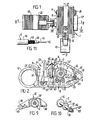
- the stripper device shown in the accompanying drawings includes a hollow body 1 which contains a plurality of disc-like cutters 2 ( Figures 2 and 4) which are mounted for rotation about a common axis.
- An opening 3 ( Figure 3) is provided through one side wall 4 of the body 1 and forms part of cable locating means whereby the' end portion 5 of a cable 6 ( Figure 4 ) can be introduced into the body 1 so as to be substantially parallel with the rotational axis of the cutters 2 .
- the device is operable to reduce the lateral spacing between the cutter axis and the axis of the cable end portion 5 so as to cause the cutters 2 to engage and penetrate into the cable 6. Relative rotation of the cable 6 and the stripper device body 1 then results in each cutter 2 tracking around the longitudinal axis of the cable end portion 5 so as to create a respective cut around the circumference of that end portion.
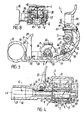
- the device body 1 is formed of two relatively movable parts, a main part 7 and a cover part 8. Relative movement between those body parts 7 and 8 enables the device to be moved between an open condition ( Figures 3 and 5) at which a cable end portion 5 can be located within the body 1 and a closed condition ( Figures 2 and 4) at which the cutters 2 engage and penetrate into the cable end portion 5. It is preferred that the two parts 7 and 8 are hinged together for relative movement about a pivot 9 as shown and a biasing spring 10 may be provided to urge the body parts 7 and 8 into the open or separated condition. Latch means 11 as hereinafter described may be provided to releasably retain the parts 7 and 8 in the closed condition.
- the cutters 2 are preferably mounted within the cover part 8 of the body 1 although they could be mounted within the main part 7 if desired. It is also preferred, as shown, that the cutters form part of a replaceable cassette 12 and there may be a plurality of such cassettes having different cutter arrangements to suit different circumstances. That is, each cassette 12 may have a particular number of cutters 2 as required for a particular use situation and which are laterally spaced and/or of preselected diameters to suit the particular use situation.
- the body main part 7 is hollow and defines a cavity 13 which is open at a top side of that main part 7.
- the cable access opening 3 is provided through one perimeter wall 4 of the main part 7 so that an end portion 5 of the cable 6 can be inserted into the cavity 13.
- That access opening 3 is formed at one end of a cable locating tube 1 4 which is connected to the perimeter wall 4 and extends laterally outwards therefrom.
- the connection between the perimeter wall 4 and the inner end portion 15 of the locating tube 14 is such that the tube 14 can be rotated about its longitudinal axis relative to the body main part 7, but is nevertheless held against separation from that main part 7 .
- the axis of the tube 14 is substantially coincident with the axis of the opening 3.
- the locating tube 14 is arranged so that a cable end portion 5 can be inserted into the outer end 16 of the open ended passage 17 formed through the tube 14 and thereby guided to adopt a correct location within the cavity 13 of the body main part 7.
- An end stop 18 is provided at the side of the main part 7 opposite the cable access opening 3 so as to be engaged by the terminal end of the cable 6 and thereby fix the axial position of the cable 6 relative to the stripper device.
- the body main part 7 also includes support means which engages and supports the cable end portion 5 against deflection away from the cutters 2 during the cutting operation.
- that support means includes a pair of laterally spaced rollers 19 which extend in the axial direction of the cable end portion 5 and have their rotational axes on respective opposite sides of the axis of the cable end portion 5.
- retainer means for releasably securing the cable 6 against withdrawal from and movable relative to the tube 14.
- that retainer means includes a toggle lever 20 which is mounted on the inner end portion of the locating tube 14 for relative movement about a pivot 21 having its axis extending transverse to the axis of the tube 14.
- a cam 22 is connected to that lever 20 and projects through an aperture 23 in the tube wall for engagement with the outer surface of the cable 6.
- the arrangement is such that in one pivotable position of the lever 20 as shown in Figure 5, the cam 22 engages the cable 6 and firmly clamps the cable 6 against separation from the stripper device and in another pivotable position of the lever 20 as shown in Figure 4, the cam 22 is clear of the cable 6 so that the cable 6 is free to move through the tube 14.
- the cover part 8 of the body 1 is preferably pivotably connected to the main part 7 at a location adjacent one side of the body 1. It is usually convenient to have the axis of the pivot 9 parallel to the longitudinal axis of a cable end portion 5 located within the body 1, but that is not essential.
- the cover part 8 is arranged for pivotable movement into and out of a closed position ( Figure 2) at which it overlies the open top of the body main part 7 and thereby substantially closes the device body 1.
- the biasing spring 1 0 for urging the two parts 7 and 8 into their open condition may comprise a coil 24 located around a pin forming the pivot 9 and connecting the two parts 7 and 8, and two arms 25 and 26 which extend laterally from respective opposite ends of that coil 24 and engage a respective one of the body parts 7 and 8.
- Latch means 11 for holding the two body parts 7 and 8 in the closed position includes a detent lever 27 which is pivotably connected to the body main part 7 so as to extend laterally outwards from the base 28 of that part 7.
- a head portion 29 of the lever 27 is arranged to pass through an opening 30 in the cover part 8 when the device is in the closed condition and has an abutment 31 which engages a surface of the cover part 8 so as to prevent opening movement of that part 8.
- a spring 32 or other resilient means may act on the lever 27 as shown to urge it about the pivot 33 so as to move in a latching direction towards a position at which the aforementioned engagement can occur.
- the lever head portion 29 is accessible externally of the cover part 8 so that it can be manually moved in the reverse direction and thereby free the cover part 8 for opening movement.
- Other forms of latching means can be adopted if desired.
- the cassette 12 is located in the cover part 8 and contains the disc-like cutters 2.
- the cutter discs 34, 35 and 36 are laterally spaced apart in the axial direction of that sleeve 37 and each has a different diameter.
- the sleeve 37 is rotatably mounted on the cassette 1 2 so that in the mounted condition of the cassette 12, the cutters 2 are exposed for engagement with a cable.
- the rotational axis of the sleeve 37 is parallel to that of the rollers 19 and in the closed condition of the body 1 the respective axes of the sleeve 37 and locating tube 14 lie in a plane which passes between the two rollers 19.
- the smaller cutter disc 34 will usually be located adjacent the locating tube 14 and the larger disc 36 will be located remote from that tube 14.
- Any suitable means may be employed to releasably hold the cassette 12 in assembly with the cover part 8.
- the connection between the cassette 12 and the cover part 8 is such as to permit some degree of relative movement so that the cassette 1 2 can move into and out of a rest position at which the cutters 2 are arranged for maximum penetration into the cable 6.
- springs 38 Figure 5
- other resilient means act between the cover part 8 and the cassette 12 so that the cassette 12 is normally held at the rest position.
- the cutter cassette 12 is removably mounted in the body 1 so as to permit replacement by different cutter arrangements.
- an end 39 of the cassette 12 is provided with a slot 40 ( Figure 9) which slidably receives the pivot pin 9 which is attached to the body 1.
- Any suitable means may be employed to releasably hold the cassette 12 against separation from the pivot pin 9, but in the construction shown that includes a retainer pin 41 which is connected to the cover part 8 at one end 42 and has its other end 43 projecting through an opening 44 in the cassette 12.
- a cross bar 45 extends laterally from the pin end 43 and the opening 44 is arranged so that the bar 45 cannot pass through that opening 44 unless the pin 41 has a particular rotational position relative to the cassette 12.
- the cross bar 45 fixes the rest position of the cassette 12 because of its engagement with an undersurface of the cassette 12.
- the pin 41 may be threadably connected to the cover part 8 so as to enable adjustment of the relative axial position of the bar 45 and thereby vary the cassette rest position.
- Other means may be adopted for that purpose.
- the cutters 2 are restrained against rotation relative to the cover part 8 in one direction.
- the clutch means includes a coil spring 46 which is neatly located about the cutter sleeve 37 and is anchored to the cassette body 1 by an arm 47 extending laterally from one end of the coil 46. There is a degree of frictional engagement between the coil 46 and the sleeve 37.
- the foregoing arrangement is such that the clutch means is responsive to the direction of turning torque which is applied to the cutter sleeve 37. That is, when the cutters 2 are influenced to rotate in one direction, the coil 46 imposes minimum resistance to that rotation. When the cutters 2 are influenced to rotate in the opposite direction, however, the resulting reaction between the sleeve 37 and coil 46 induces the coil 46 to close more tightly about the sleeve 37 and thereby clamp the sleeve 37 so that it is held against rotation. That clamping engagement is automatically released when the turning influence is removed from the cutters 2 or when the cutters 2 are influenced to rotate in the first mentioned direction. It will be apparent that other forms of clutches may be satisfactory for the purpose stated.
- the cable end stop 18 is preferably in the form of a lever as shown in Figures 6 and 7 which is connected to the cover part 8 so as to move with that cover part 8.
- an end portion 48 of the lever 1 8 overlies an opening 49 formed through the side wall 50 of the body part 7 which is opposite to the wall 4.
- the cable end portion 5 is receivable in the opening 49 so as to be engageable with the lever end portion 48 and thereby fix the axial position of the cable 6.
- the lever 18 is swung out of the way so as to be clear of the opening 49 and is thereby unable to resist outward axial movement of the cable 6. That has the advantage of allowing the cable 6 to expand axially during the cutting operation and thereby avoids end loading which could break the cable 6 or otherwise disturb the neatness of the stripping operation.
- a second stop is arranged to adopt an operative position at which it is located over the opening 49 when the body parts 7 and 8 are closed.
- That second stop may be a plate 57 secured to or formed - integral with the cover part 8 and arranged to overlie the opening 49 in the closed position, but not the open position, of the body 1.
- the plate 57 is thereby arranged in axial alignment with the cable 6 when the body parts 7 and 8 are in the closed position, but has its innermost surface located further outwards from the wall 50 than the innermost surface of the lever end portion 48.. That is, the clearance between the stop plate 57 and the wall 50 is greater than that between the stop lever 18 and the wall 50.
- the plate 57 is therefore arranged so as not to substantially impede the aforementioned axial expansion of the cable 6, but it may nevertheless be engaged by the terminal end of the cable 6 in the course of the cutting operation.
- the device body 1 is opened and the lever 20 is in the Figure 4 position when it is desired to locate a cable end portion 5 within the body 1. That end portion 5 is inserted through the locating tube 14 until its terminal end engages the stop 18, which is located as shown in Figure 6, and the lever 20 is then swung to the Figure 5 position to clamp the cable 6. The cover part 8 is then swung towards the main part 7 of the body 1 and during that movement the stop 18 is automatically moved towards the position shown in Figure 7. Also, at least the largest cutter disc 36 engages against the outer surface of the cable end portion 5.
- each cutter disc 34, 35 and 3 6 tracks around the circumference of the cable end portion 5 and cuts into the cable insulation.
- the depth of each such cut may increase with repeated relative rotation of the body 1 because of the progressively decreasing resistance to movement of the cassette 12 towards its rest position or position of minimum depression.
- the cutters 2 are preselected so that at the position of minimum depression of the cassette 12 each cutter disc 34, 35 and 36 will have cut into the cable 6 to the required depth.
- the smaller cutter disc 34 will have cut through the outer insulation 52 ( Figure 11) of the cable 6, the intermediate cutter disc 35 will have penetrated through the metal sheath 53 between the two insulation layers 52 and 54 and the larger cutter disc 36 will have penetrated through to the core 55 of the cable 6 (e.g., metal wire).
- the lever 20 is then released so that the length of cable 6 can be withdrawn out of the locating tube 14. That action automatically causes stripping of the cable end portion 5 beyond each of the three cuts because the cutters 2 are still embedded into the cable 6 and therefore act as stripping elements.
- That action automatically causes stripping of the cable end portion 5 beyond each of the three cuts because the cutters 2 are still embedded into the cable 6 and therefore act as stripping elements.
- the cable 6 is fully withdrawn, there will be an exposed length of core 55 at the very end, an exposed length of the inner insulation 54 spaced from the terminal end 56, and an exposed section of the metal sheath 53 spaced even further from the terminal end 56, as shown in Figure 11. Different arrangements will of course result from use of different cutter assemblies.
- the cable end stop plate 57 may carry a plunger (not shown) which is accessible from the exterior of the body 1 and which can be depressed to free offcuts perhaps jammed within the device adjacent the stop plate 57. Opening of the body 1 enables the offcuts to be discharged so that the device is ready for further operation.
- a device as described is of relatively simple construction and is extremely convenient to operate. It is particularly advantageous that the device can perform a series of cuts in a single operation without the need for separate adjustment for each cut as is the case with some prior devices of the same kind.
Landscapes
- Removal Of Insulation Or Armoring From Wires Or Cables (AREA)
- Knives (AREA)
Applications Claiming Priority (2)
| Application Number | Priority Date | Filing Date | Title |
|---|---|---|---|
| AUPH399385 | 1985-12-23 | ||
| AU3993/85 | 1985-12-23 |
Publications (2)
| Publication Number | Publication Date |
|---|---|
| EP0227466A2 true EP0227466A2 (fr) | 1987-07-01 |
| EP0227466A3 EP0227466A3 (fr) | 1988-07-20 |
Family
ID=3771421
Family Applications (1)
| Application Number | Title | Priority Date | Filing Date |
|---|---|---|---|
| EP86310028A Withdrawn EP0227466A3 (fr) | 1985-12-23 | 1986-12-22 | Outils pour dénuder des fils |
Country Status (5)
| Country | Link |
|---|---|
| US (1) | US4730391A (fr) |
| EP (1) | EP0227466A3 (fr) |
| JP (1) | JPS62173908A (fr) |
| KR (1) | KR870006690A (fr) |
| NZ (1) | NZ218766A (fr) |
Cited By (1)
| Publication number | Priority date | Publication date | Assignee | Title |
|---|---|---|---|---|
| GB2231733B (en) * | 1989-05-10 | 1993-06-30 | Zdzislaw Bieganski | Coaxial cable stripper |
Families Citing this family (17)
| Publication number | Priority date | Publication date | Assignee | Title |
|---|---|---|---|---|
| JPH0275918U (fr) * | 1988-11-28 | 1990-06-11 | ||
| US4945636A (en) * | 1989-01-11 | 1990-08-07 | Canare Electric Co., Ltd. | Coaxial cable stripper |
| US5016398A (en) * | 1989-06-06 | 1991-05-21 | Akio Fukunaga | Wire stripping apparatus |
| US4985996A (en) * | 1989-08-25 | 1991-01-22 | Rostra Tool Company | Wire stripper with V-notch blade |
| US5036734A (en) * | 1989-10-25 | 1991-08-06 | Ben Hughes Communication Products Co. | Cable stripping tool |
| JP2980568B2 (ja) * | 1997-04-28 | 1999-11-22 | カナレ電気株式会社 | ケーブルストリッパ |
| ES2196940B1 (es) * | 2001-02-15 | 2005-03-01 | Juan Manuel Optral S.A. | Dispositivo para la eliminacion de la trenza, malla o carcasa exterior de un cable o cabo. |
| US6467171B2 (en) | 2001-03-09 | 2002-10-22 | Capewell Components Company, Llc | Compound coaxial cable stripping tool |
| JP2004523998A (ja) * | 2001-03-10 | 2004-08-05 | フィッシャー コネクターズ ホールディング ソシエテ アノニム | 同軸ケーブルのストリッパ |
| US6739229B2 (en) | 2002-06-19 | 2004-05-25 | Thomas D. Scollon | Cable stripping device |
| US6779273B1 (en) * | 2003-03-27 | 2004-08-24 | Lucent Technologies Inc. | Coaxial cable cutting tool |
| USD515901S1 (en) | 2004-02-27 | 2006-02-28 | Capewell Components Company, Llc | Combination coaxial cable stripping tool and conductor cleaner |
| DE102007038626B3 (de) * | 2007-08-16 | 2008-10-09 | Wezag Gmbh Werkzeugfabrik | Zange zum Abisolieren eines Kabels |
| US8151670B2 (en) * | 2008-08-01 | 2012-04-10 | Nelson James M | Sheath and conductor strippers |
| CN107534276B (zh) * | 2015-05-11 | 2021-03-09 | 胡贝尔和茹纳股份公司 | 剥线工具 |
| GB2545883A (en) * | 2015-11-04 | 2017-07-05 | Hellermann Tyton Ltd | A cable stripping tool for electrical cables |
| US11469577B1 (en) * | 2021-05-11 | 2022-10-11 | Bruce G. Phillips | Cable cutter saw |
Family Cites Families (10)
| Publication number | Priority date | Publication date | Assignee | Title |
|---|---|---|---|---|
| US2120398A (en) * | 1937-01-16 | 1938-06-14 | Bell Telephone Labor Inc | Cable stripping tool |
| US2695537A (en) * | 1952-04-08 | 1954-11-30 | William D Imman | Coaxial cable stripper |
| FR1344490A (fr) * | 1962-10-19 | 1963-11-29 | Machine pour débiter un câble en tronçons et pour dénuder simultanément les extrémités de ces tronçons | |
| US3161088A (en) * | 1962-12-04 | 1964-12-15 | Harold J Tolman | Stripper for coaxial cables |
| US3216110A (en) * | 1963-06-14 | 1965-11-09 | Douglas S Stallings | Operating heads for insulation strippers |
| US3254407A (en) * | 1964-01-13 | 1966-06-07 | Amp Inc | Insulation stripper of simprlified construction having improved safety features |
| US3407497A (en) * | 1967-02-23 | 1968-10-29 | Albert P. Ratay | Coaxial cable stripping device |
| NL188438C (nl) * | 1976-06-09 | 1992-06-16 | Pressmaster Tool Ab | Inrichting voor het verwijderen van de bekleding van een in hoofdzaak staafvormig voorwerp. |
| GB2133637B (en) * | 1983-01-13 | 1986-07-02 | Zdzislaw Bieganski | Cable stripper |
| SE8304627D0 (sv) * | 1983-08-26 | 1983-08-26 | Weidmueller C A Gmbh Co | Abisoliergeret fur koaxialkabel |
-
1986
- 1986-12-19 US US06/943,778 patent/US4730391A/en not_active Expired - Fee Related
- 1986-12-22 EP EP86310028A patent/EP0227466A3/fr not_active Withdrawn
- 1986-12-22 NZ NZ218766A patent/NZ218766A/xx unknown
- 1986-12-23 KR KR860011142A patent/KR870006690A/ko not_active Withdrawn
- 1986-12-23 JP JP61307561A patent/JPS62173908A/ja active Pending
Cited By (1)
| Publication number | Priority date | Publication date | Assignee | Title |
|---|---|---|---|---|
| GB2231733B (en) * | 1989-05-10 | 1993-06-30 | Zdzislaw Bieganski | Coaxial cable stripper |
Also Published As
| Publication number | Publication date |
|---|---|
| KR870006690A (ko) | 1987-07-14 |
| EP0227466A3 (fr) | 1988-07-20 |
| NZ218766A (en) | 1988-06-30 |
| US4730391A (en) | 1988-03-15 |
| JPS62173908A (ja) | 1987-07-30 |
Similar Documents
| Publication | Publication Date | Title |
|---|---|---|
| US4730391A (en) | Wire stripper | |
| US4829671A (en) | Copper cable wire peeler | |
| US6308417B1 (en) | Tool for separating and removing cable jackets and insulation from cables | |
| JP2980568B2 (ja) | ケーブルストリッパ | |
| US4979299A (en) | Coaxial cable stripper | |
| US5713132A (en) | Coaxial cable trimmer | |
| EP1533088A2 (fr) | Ensemble de lames pour la coupe de matériaux en feuille | |
| US4977671A (en) | Saw for cutting large diameter shielded conduit | |
| EP2374585B1 (fr) | Dispositif de réglage de l'angle de biseau pour scie circulaire | |
| JPS6127968B2 (fr) | ||
| US4279551A (en) | Hole saw pilot pin with plug retrieval mechanism | |
| PL136399B1 (en) | Single-bladed reamer | |
| US5230150A (en) | Tubing cutter applying continuous cutting force to tubing | |
| US4581824A (en) | Portable adjustable washer cutter and improved washer | |
| US6260785B1 (en) | Line rewinder apparatus | |
| US4104791A (en) | Stripper for coated wires | |
| US5388082A (en) | Watch case back opener | |
| US20080047147A1 (en) | Shielded conduit cutting device for small BX electrical cables | |
| US5009005A (en) | Cable stripper | |
| EP0976511A2 (fr) | Cassette pour lame de coupe ainsi que son dispositif de fixation | |
| US4974650A (en) | Safety guard stop for power tool | |
| US3922779A (en) | Cable stripper | |
| US4813144A (en) | Armored cable cutting device | |
| CN86108638A (zh) | 剥线器 | |
| GB2284945A (en) | Tools for cutting and stripping cables |
Legal Events
| Date | Code | Title | Description |
|---|---|---|---|
| PUAI | Public reference made under article 153(3) epc to a published international application that has entered the european phase |
Free format text: ORIGINAL CODE: 0009012 |
|
| AK | Designated contracting states |
Kind code of ref document: A2 Designated state(s): AT BE CH DE FR GB IT LI LU NL SE |
|
| PUAL | Search report despatched |
Free format text: ORIGINAL CODE: 0009013 |
|
| AK | Designated contracting states |
Kind code of ref document: A3 Designated state(s): AT BE CH DE FR GB IT LI LU NL SE |
|
| 17P | Request for examination filed |
Effective date: 19890120 |
|
| 17Q | First examination report despatched |
Effective date: 19910122 |
|
| STAA | Information on the status of an ep patent application or granted ep patent |
Free format text: STATUS: THE APPLICATION IS DEEMED TO BE WITHDRAWN |
|
| 18D | Application deemed to be withdrawn |
Effective date: 19910802 |
|
| RIN1 | Information on inventor provided before grant (corrected) |
Inventor name: WOOD,HAROLD |