EP0227579A2 - Passage de refroidissement avec chambre de tourbillonnement - Google Patents
Passage de refroidissement avec chambre de tourbillonnement Download PDFInfo
- Publication number
- EP0227579A2 EP0227579A2 EP86630195A EP86630195A EP0227579A2 EP 0227579 A2 EP0227579 A2 EP 0227579A2 EP 86630195 A EP86630195 A EP 86630195A EP 86630195 A EP86630195 A EP 86630195A EP 0227579 A2 EP0227579 A2 EP 0227579A2
- Authority
- EP
- European Patent Office
- Prior art keywords
- slot
- coolant
- airfoil
- channel
- wall
- Prior art date
- Legal status (The legal status is an assumption and is not a legal conclusion. Google has not performed a legal analysis and makes no representation as to the accuracy of the status listed.)
- Granted
Links
Images


Classifications
-
- F—MECHANICAL ENGINEERING; LIGHTING; HEATING; WEAPONS; BLASTING
- F01—MACHINES OR ENGINES IN GENERAL; ENGINE PLANTS IN GENERAL; STEAM ENGINES
- F01D—NON-POSITIVE DISPLACEMENT MACHINES OR ENGINES, e.g. STEAM TURBINES
- F01D5/00—Blades; Blade-carrying members; Heating, heat-insulating, cooling or antivibration means on the blades or the members
- F01D5/12—Blades
- F01D5/14—Form or construction
- F01D5/18—Hollow blades, i.e. blades with cooling or heating channels or cavities; Heating, heat-insulating or cooling means on blades
- F01D5/186—Film cooling
-
- Y—GENERAL TAGGING OF NEW TECHNOLOGICAL DEVELOPMENTS; GENERAL TAGGING OF CROSS-SECTIONAL TECHNOLOGIES SPANNING OVER SEVERAL SECTIONS OF THE IPC; TECHNICAL SUBJECTS COVERED BY FORMER USPC CROSS-REFERENCE ART COLLECTIONS [XRACs] AND DIGESTS
- Y02—TECHNOLOGIES OR APPLICATIONS FOR MITIGATION OR ADAPTATION AGAINST CLIMATE CHANGE
- Y02T—CLIMATE CHANGE MITIGATION TECHNOLOGIES RELATED TO TRANSPORTATION
- Y02T50/00—Aeronautics or air transport
- Y02T50/60—Efficient propulsion technologies, e.g. for aircraft
Definitions
- This invention relates to film cooling, and more particularly to film cooled airfoils.
- the external surface of airfoils may be cooled by conducting cooling air from an internal cavity to the external surface via a plurality of small passages. It is desired that the air exiting the passages remain entrained in the boundary layer on the surface of the airfoil for as long a distance as possible downstream of the passage to provide a protective film of cool air... between the hot mainstream gas and the airfoil surface.
- the angle which the axis of the passage makes with the airfoil surface and its relation to the direction of hot gas flow over the airfoil surface at the passage breakout are important factors which influence film cooling effectiveness.
- Film cooling effectiveness decreases rapidly with distance x from the passage outlet. Maintaining high film cooling effectiveness for as long a distance as possible over as large a surface area as possible is the main goal of airfoil film cooling.
- the total of the metering areas for all the cooling passages and orifices leading from the airfoil controls the total flow rate of coolant from the airfoil, assuming internal and external pressures are fixed or at least beyond the designer's control.
- the designer has the job of specifying the passage size and the spacing between passages, as well as the shape and orientation of the passages, such that all areas of the airfoil are maintained below critical design temperature limits determined by the airfoil material capability, maximum stress, and life requirement considerations.
- the air leaving the passage exit generally forms a cooling film stripe no wider than or hardly wider than the dimension of the passage exit perpendicular to the gas flow.
- Limitations on the number, size, and spacing of cooling passages results in gaps in the protective film and/or areas of low film cooling effectiveness which may produce localized hot spots. Airfoil hot spots are one factor which limits the operating temperature of the engine.
- U.S. Patent 3,527,543 to Howald uses divergently tapered passages of circular cross section to increase the entrainment of coolant in the boundary layer from a given passage.
- the passages are also preferably oriented in a plane extending in the longitudinal direction or partially toward the gas flow direction to spread the coolant longitudinally upon its exit from the passage as it moves downstream.
- the velocity of the air leaving the cooling passage is dependent on the ratio of its pressure at the passage inlet to the pressure of the gas stream at the passage outlet. In general the higher the pressure ratio, the higher the exit velocity. Too high an exit velocity results in the cooling air penetrating into the gas stream and being carried away without providing effective film cooling. Too low a pressure ratio will result in gas stream ingestion into the cooling passage causing a complete loss of local airfoil cooling. Total loss of airfoil cooling usually has disastrous results, and because of this a margin of safety is usually maintained. This extra pressure for the safety margin drives the design toward the high pressure ratios. Tolerance of high pressure ratios is a desirable feature of film cooling designs.
- Japanese Patent 55-ll4806 shows, in its Figs. 2 and 3 (reproduced herein as prior art Figures l3 and l4), a hollow airfoil having straight cylindrical passages disposed in a longitudinal row and emptying into a longitudinally extending slot formed in the external surface of the airfoil. While that patent appears to teach that the flow of cooling fluid from adjacent passages blends to form a film of cooling fluid of uniform thickness over the full length of the slot by the time the cooling fluid exits the slot and reaches the airfoil surface, our test experience indicates that the coolant fluid from the cylindrical passages moves downstream as a stripe of essentially constant width, which is substantially the diameter of the passage. Any diffusion which results in blending of adjacent stripes of coolant fluid occurs so far downstream that film cooling effectiveness at that point is well below what is required for most airfoil designs.
- U.S. Patent No. 3,5l5,499 to Beer et al describes an airfoil made from a stack of etched wafers.
- the finished airfoil includes several areas having a plurality of longitudinally spaced apart passages leading from an internal cavity to a common, longitudinally extending slot from which the cooling air is said to issue to form a film of cooling air over the airfoil external surface.
- each passage appears to converge from its inlet to a minimum cross-sectional area where it intersects the slot.
- the passage appears to have a small, constant size which exits into a considerably wider slot. Both configurations are likely to have the same drawbacks as discussed with respect to the Japanese patent; that is, the cooling fluid will not uniformly fill the slot before it enters the main gas stream, and considerably less than l00% film coverage downstream of the slot is likely.
- U.S. Patent No. 4,303,374 shows a configuration for cooling the exposed, cut-back surface of the trailing edge of an airfoil.
- the configuration includes a plurality of longitudinally spaced apart, diverging passages within the trailing edge. Adjacent passages meet at their outlet ends to form a continuous film of cooling air over the cut-back surface.
- One object of the present invention is improved means for cooling a wall over which a hot gas stream is flowing.
- a wall to be cooled is adapted to have a coolant fluid on a first side thereof and a hot gas flowing on a second side thereof, wherein the wall includes a cylindrical diffuser channel formed therein having an axis extending in a first direction, a metering passage extending from the coolant fluid side of the wall and intersecting the cylindrical surface of the channel for introducing a metered amount of coolant fluid into the channel, and a slot elongated in the first direction having one end intersecting substantially the full length of the cylindrical channel to form the slot inlet and the other end intersecting the surface of the second side of the wall to define the slot outlet, wherein the metering passage is oriented to direct coolant fluid into the cylindrical channel to impart a swirling motion to the fluid, and wherein the slot is oriented to direct coolant fluid from the channel outlet as a film over the surface of the second side of the wall.
- the cylindrical channel acts as a diffuser and swirler, creating turbulence in the flow as it leaves the metering section.
- the coolant leaves the channel via the slot inlet and spreads out to fill the entire slot before it leaves the slot outlet and becomes a continuous film on the wall surface which extends the full length of the slot. It is believed that the swirling and turbulence causes diffusion of the coolant fluid within the channel and is the mechanism which helps the coolant fill the entire slot, achieving a continuous coolant film over the length of the slot for maximum cooling effectiveness.
- the present invention is particularly suited to cooling the walls of a hollow airfoil, such as is used in the turbine section of a gas turbine engine.
- the walls of the airfoil define a coolant compartment therewithin which receives coolant fluid, under pressure, from elsewhere in the engine.
- the slot is basically comprised of a pair of closely spaced apart walls which may be parallel from the slot inlet to outlet, or which may be parallel near the slot inlet and then may diverge to the outlet.
- the slot is elongated in the spanwise direction of the airfoil.
- the number of metering passages which feed the cylindrical channel depend upon the length of the slot, which is substantially the same as the length of the cylindrical channel.
- the metering passages are preferably oriented to direct the coolant fluid into the channel substantially tangential to the surface of the channel or in such a manner as to impart a swirling motion to the fluid about the axis of the channel.
- the slot walls intersect the hot outer surface of the airfoil at a shallow angle to direct the coolant fluid from the slot in the direction of the hot gas flow over the surface (i.e., the downstream direction) such that the coolant becomes entrained in the boundary layer on external surface of the airfoil and remains entrained for a considerable distance downstream of the slot outlet.
- the coolant thereby provides a thermal barrier between the airfoil surface and the hot gas.
- the blade l0 comprises a hollow airfoil l2 which extends in a spanwise or longitudinal direction from a root l4 which is integral therewith.
- a platform l6 is disposed at the base of the airfoil l2.
- the airfoil l2 comprises a wall l8 having an outer surface 20 and an inner surface 22.
- the inner surface 22 defines a longitudinally extending internal cavity which is divided into a plurality of adjacent longitudinally extending compartments 24, 26, 28, respectively, by longitudinally extending ribs 30, 32.
- the passages 34, 36 within the root l4 communicate with the compartments 24, 26, and 28.
- coolant pressure from a suitable source such as compressor bleed air, is fed into the passages 34, 36 and pressurizes the compartments 24, 26, and 28.
- the airfoil l2 is formed of a plurality of cordwise extending wafers 38.
- Each wafer has an external airfoil shape, and is formed with holes, notches, channels, and the like, such that when the wafers are stacked and bonded to each other they form the airfoil l2 with all the desired channels and cavities therewithin.
- Blades and airfoils made from wafers of this type are well known in the art. For example, they are described in U.S. Patent No. 3,5l5,499 Beer et al and commonly owned U.S. Patent No. 3,30l,526 Chamberlin, both of which are incorporated herein by reference.
- the arrows 40 represent the direction of flow (i.e., streamlines) of hot gases over the surface of the airfoil.
- the directon of flow of hot gases over either the pressure or suction side surfaces of the airfoil shall be considered the downstream direction.
- the downstream directon is tangent to the surface of the airfoil and, except, perhaps, close to the airfoil tip or the airfoil base near the platform l6 where atypical currents are generated, is substantially perpendicular to the spanwise direction of the airfoil.
- the airfoil l2 includes a longitudinally extending slot 42 in the suction side of the airfoil wall l8.
- the slot 42 extends over substantially the full spanwise length of the airfoil, although, as will be described hereinafter with respect to an alternate embodiment of the present invention, this is not a requirement.
- the slot 42 is comprised of a pair of parallel, closely spaced apart, oppositely facing, longitudinally extending surfaces 44, 46 which intersect the external surface 20 of the airfoil to form a longitudinally extending slot outlet 48.
- a cylindrical channel 50 is formed in the wall l8, has its axis 52 parallel to the length of the slot 42, and is substantially the same length as the slot 42.
- the walls 44, 46 intersect the surface 54 of the channel 50 to define the slot inlet 56.
- a plurality of cylindrical metering passages 58 are spaced apart along the longitudinal length of the channel 50.
- Each metering passage 58 intersects the internal wall 22 of the airfoil to define a plurality of inlets 60; and they intersect the surface 54 of the channel 50 to form metering passage outlets 62.
- the passages 58 thereby provide fluid communication between the coolant compartment 26 and the channel 50.
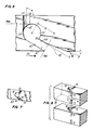
- each metering passage 58 is formed in opposing surfaces of adjacent waffers to define the entire metering passage when the waffers are bonded together. There need not be a metering passage 58 at every interface, although, for purposes of illustration, this is shown to be the case in Fig. 4.
- the metering passages 58 are oriented to direct coolant fluid from the compartment 26 into the channel 50 substantially tangential to the channel wall 54 so as to impart a swirling motion to the fluid about the axis 52 of the channel.
- the air leaves the metering passage 58 it diffuses since the volume of the channel 50 is many times larger than the total volume of all the metering passages 58 which carry coolant into the channel.
- the swirling of the coolant while diffusing improves its heat transfer capabilities byincreasing the amount of surface area of the channel 50 with which it comes into contact.
- the slot 42 is oriented to direct coolant fluid from its outlet 48 in a downstream direction.
- the surfaces 44, 46 intersect the external surface 20 of the airfoil at a shallow angle of no more than about 40° and most preferably 30° or less. This minimizes penetration of the coolant stream into the hot gas stream in a direction perpendicular to the outer surface of the airfoil. Excessive penetration can result in the coolant being immediately swept away from the surface 20 of the airfoil as opposed to remaining attached to the surface of the airfoil as a film of coolant downstream of the slot outlet 48.
- the slot surface 44 is hereinafter referred to as the downstream surface 44
- the slot surface 46 is hereinafter referred to as the upstream surface 46 in view of their positions relative to each other and the downstream direction 40.
- the creation of swirling movement of coolant fluid within the channel 50 is an important aspect of the present invention. It is therefore important that the metering passages 58 do not have their centerlines substantially in the plane of the slot. If they were aligned, then coolant fluid from the passages 58 would flow along direct lines into the slot 42. A substantial portion of that fluid would remain as a cohesive stream of circular cross-section as it passes into and through the slot. It would tend to leave the slot outlet 48 as narrow concentrations of fluid along the length of the slot outlet. Most preferably the metering passages 58 and the slot 42 are oriented relative to the cylindrical channel 50 such that not only is the coolant fluid swirled within the channel 50 (in the direction of the arrow 5l in Fig.
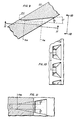
- Fig. 6 shows an alternate embodiment for the coolant passage configuration of the present invention. Elements and features of Fig. 6 which have corresponding elements and features in Fig. 3 have been identified using the same reference numerals as in Fig. 3, except primed. In this embodiment the metering passages have been relocated to show an alternate, acceptable orientation. Also, although the slot surfaces 44′, 46′ are parallel for a short distance from the slot inlet 56′, the downstream surface 44′ thereafter diverges from the surface 46′ at a small angle ⁇ of preferably l0° or less. This reduces the angle at which the air is ejected relative to the downstream direction 40 at the slot outlet, which helps the coolant fluid attach itself to the wall downstream of the slot outlet.
- the airfoil l2 also includes a row of longitudinally spaced apart slots 70 which is fed coolant from the compartment 24.
- Each slot 70 communicates with a cylindrical channel 72 whose axis is parallel to the spanwise length of the slot 70.
- Each channel 72 is intersected by a single metering passage 74.
- the essential difference between this alternate configuration and the configuration described with respect to Figs. 3-5 is that the slots 70, although having outlets 76 which are elongated in the spanwise direction, are fairly short.
- the cylindrical channels 72 are correspondingly short in length. In this exemplary embodiment the short length requires only a single metering passage 74 for each slot 70.
- the slot cross-sectional area can be set at any value to optimize film cooling effectiveness.
- each slot 70, channel 72, and cylindrical metering passage 74 are formed in the abutting, bonded together surfaces of adjacent wafers 38 such that when the wafers are bonded together the corresponding halves of the slot 70, channel 72, and passage 74 are aligned to define a complete coolant passage extending from the compartment 24 to the external surface 20 of the airfoil.
- FIG. l2 For purposes of clarity the airfoil l2 shown in Figs. l and 2 has been greatly simplified.
- An actual turbine airfoil might include several slots, like the slot 48, and several rows of slots, like the slots 70, or spanwise rows of coolant passages of other configurations well known in the art. These slots and coolant passages, including those of the present invention, could be on either the pressure or suction side of the airfoil.
- the airfoil shown in the drawing is intended to be illustrative only and not limiting.
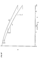
- the horizontal axis is a dimensionless parameter P whose value is the ratio of the distance x from the outlet of the cooling passage (in the direction of the mainstream gas flow over the outlet) to a number directly related to the mass flow rate of cooling air exiting the passage.
- the vertical axis is a measure of the film cooling effectiveness E (as hereinabove defined) measured at the distance x downstream of the passage outlet.
- the maximum possible cooling effectiveness is l.0.
- each point on the curves is the result of an average of a plurality of temperature measurements taken along either the full length of the row of holes 200 or along the full length of the slot, as the case may be. Because P is directly related to the distance from the passage outlet, and since the distance downstream of the outlet is the only variable in these tests, P may be considered as the measure of distance downstream of the passage outlet.
- the curve labeled A is for a row of baseline shaped holes 200 through a test plate 202 such as shown in Figs. 9-ll.
- the area ratio A e /A m for each passage was 3.6, where A e (exit area) is the cross-sectional area of the passage outlet measured in the plane labeled A e in Fig. 9, and where A m (metering area) is the cross-sectional area of the metering section 204 (Fig. 9) as measured in the plane labeled A m .
- the pitch to diameter ratio, p/d was 6.58, wherein p (Fig. l0) is the distance between the centers of adjacent metering sections 200, and d is the effective diameter of the metering section, which is the diameter of a circle having the cross-sectional area A m .
- the curve B is for a coolant passage according to the present invention formed in a flat test plate approximately l7 inches long, l.6 inches wide, and 0.75 inches thick. (The thickness of the plate corresponds to the thickness of the wall to be cooled.)
- the cylindrical channel and the slot intersecting the channel extended about l6.3 inches or substantially the full length of the plate.
- the angle ⁇ was 90°; the angle ⁇ was l0°; the angle ⁇ 1 was 20°;
- the area ratio A e /A m was 8.2; and the pitch to diameter ratio p/d was 5.48.
- a e was measured in the plane having that designation in Fig. 6.
- a m was the sum of all the cross-sectional areas of the metering passages 58′ as measured in the plane labeled A m in Fig. 6.
- the pitch p was the distance between the centers of the metering passages 58′; and the diameter d was the effective diameter of a metering passage, which is the diameter of a circle having the same cross-sectional area as a metering passage.
- the metering passage was circular in cross section and had an effective diameter of about 0.l6 inch.
- the distance s between the axis of the cylindrical channel and the exit plane A e was about 0.45 inch.
- the improvement in film cooling effectiveness, E, provided by the present invention as compared to the baseline shaped holes is significant and can readily be seen in the graph of Fig. l2.
- the baseline shaped holes had a cooling effectiveness about .05 less than the test configuration of the present invention.
- the difference was about .03.
- a 0.02 increase in cooling effectiveness translates into about a 28 °F decrease in the temperature of the coolant film for the same mass flow rate of coolant.
Landscapes
- Engineering & Computer Science (AREA)
- Mechanical Engineering (AREA)
- General Engineering & Computer Science (AREA)
- Turbine Rotor Nozzle Sealing (AREA)
Applications Claiming Priority (2)
| Application Number | Priority Date | Filing Date | Title |
|---|---|---|---|
| US06/812,102 US4669957A (en) | 1985-12-23 | 1985-12-23 | Film coolant passage with swirl diffuser |
| US812102 | 1985-12-23 |
Publications (3)
| Publication Number | Publication Date |
|---|---|
| EP0227579A2 true EP0227579A2 (fr) | 1987-07-01 |
| EP0227579A3 EP0227579A3 (en) | 1989-04-12 |
| EP0227579B1 EP0227579B1 (fr) | 1992-01-29 |
Family
ID=25208508
Family Applications (1)
| Application Number | Title | Priority Date | Filing Date |
|---|---|---|---|
| EP86630195A Expired - Lifetime EP0227579B1 (fr) | 1985-12-23 | 1986-12-18 | Passage de refroidissement avec chambre de tourbillonnement |
Country Status (8)
| Country | Link |
|---|---|
| US (1) | US4669957A (fr) |
| EP (1) | EP0227579B1 (fr) |
| JP (1) | JPH07103803B2 (fr) |
| CN (1) | CN1010332B (fr) |
| AU (1) | AU597922B2 (fr) |
| CA (1) | CA1274775A (fr) |
| DE (2) | DE3683743D1 (fr) |
| IL (1) | IL81033A (fr) |
Cited By (3)
| Publication number | Priority date | Publication date | Assignee | Title |
|---|---|---|---|---|
| EP0375175A1 (fr) * | 1988-12-23 | 1990-06-27 | ROLLS-ROYCE plc | Composants refroidis pour turbomachines |
| EP1529580A1 (fr) * | 2003-10-29 | 2005-05-11 | Siemens Aktiengesellschaft | Moule de fonderie |
| WO2022002755A1 (fr) | 2020-07-02 | 2022-01-06 | Siemens Aktiengesellschaft | Composant de gaz chaud d'une turbine à gaz |
Families Citing this family (66)
| Publication number | Priority date | Publication date | Assignee | Title |
|---|---|---|---|---|
| US4684323A (en) * | 1985-12-23 | 1987-08-04 | United Technologies Corporation | Film cooling passages with curved corners |
| US6139258A (en) * | 1987-03-30 | 2000-10-31 | United Technologies Corporation | Airfoils with leading edge pockets for reduced heat transfer |
| JPH0819183B2 (ja) * | 1987-07-03 | 1996-02-28 | 三井石油化学工業株式会社 | オレフイン重合用固体触媒の製法 |
| US4923371A (en) * | 1988-04-01 | 1990-05-08 | General Electric Company | Wall having cooling passage |
| US5326224A (en) * | 1991-03-01 | 1994-07-05 | General Electric Company | Cooling hole arrangements in jet engine components exposed to hot gas flow |
| US5419681A (en) * | 1993-01-25 | 1995-05-30 | General Electric Company | Film cooled wall |
| US5458461A (en) * | 1994-12-12 | 1995-10-17 | General Electric Company | Film cooled slotted wall |
| US6092982A (en) * | 1996-05-28 | 2000-07-25 | Kabushiki Kaisha Toshiba | Cooling system for a main body used in a gas stream |
| US6383602B1 (en) * | 1996-12-23 | 2002-05-07 | General Electric Company | Method for improving the cooling effectiveness of a gaseous coolant stream which flows through a substrate, and related articles of manufacture |
| US6050777A (en) * | 1997-12-17 | 2000-04-18 | United Technologies Corporation | Apparatus and method for cooling an airfoil for a gas turbine engine |
| US6099251A (en) * | 1998-07-06 | 2000-08-08 | United Technologies Corporation | Coolable airfoil for a gas turbine engine |
| US6247896B1 (en) | 1999-06-23 | 2001-06-19 | United Technologies Corporation | Method and apparatus for cooling an airfoil |
| US6234755B1 (en) * | 1999-10-04 | 2001-05-22 | General Electric Company | Method for improving the cooling effectiveness of a gaseous coolant stream, and related articles of manufacture |
| US6402470B1 (en) | 1999-10-05 | 2002-06-11 | United Technologies Corporation | Method and apparatus for cooling a wall within a gas turbine engine |
| US6254334B1 (en) | 1999-10-05 | 2001-07-03 | United Technologies Corporation | Method and apparatus for cooling a wall within a gas turbine engine |
| US6254347B1 (en) * | 1999-11-03 | 2001-07-03 | General Electric Company | Striated cooling hole |
| US6280140B1 (en) | 1999-11-18 | 2001-08-28 | United Technologies Corporation | Method and apparatus for cooling an airfoil |
| DE10001109B4 (de) | 2000-01-13 | 2012-01-19 | Alstom Technology Ltd. | Gekühlte Schaufel für eine Gasturbine |
| DE10053356A1 (de) * | 2000-10-27 | 2002-05-08 | Alstom Switzerland Ltd | Gekühltes Bauteil, Gusskern für die Herstellung eines solchen Bauteils, sowie Verfahren zum Herstellen eines solchen Bauteils |
| US6705831B2 (en) * | 2002-06-19 | 2004-03-16 | United Technologies Corporation | Linked, manufacturable, non-plugging microcircuits |
| US6981846B2 (en) * | 2003-03-12 | 2006-01-03 | Florida Turbine Technologies, Inc. | Vortex cooling of turbine blades |
| JP4191578B2 (ja) * | 2003-11-21 | 2008-12-03 | 三菱重工業株式会社 | ガスタービンエンジンのタービン冷却翼 |
| US6916150B2 (en) * | 2003-11-26 | 2005-07-12 | Siemens Westinghouse Power Corporation | Cooling system for a tip of a turbine blade |
| GB0418914D0 (en) * | 2004-08-25 | 2004-09-29 | Rolls Royce Plc | Turbine component |
| JP4898253B2 (ja) * | 2005-03-30 | 2012-03-14 | 三菱重工業株式会社 | ガスタービン用高温部材 |
| JP5039837B2 (ja) * | 2005-03-30 | 2012-10-03 | 三菱重工業株式会社 | ガスタービン用高温部材 |
| US7249934B2 (en) | 2005-08-31 | 2007-07-31 | General Electric Company | Pattern cooled turbine airfoil |
| US7520723B2 (en) * | 2006-07-07 | 2009-04-21 | Siemens Energy, Inc. | Turbine airfoil cooling system with near wall vortex cooling chambers |
| US7866948B1 (en) | 2006-08-16 | 2011-01-11 | Florida Turbine Technologies, Inc. | Turbine airfoil with near-wall impingement and vortex cooling |
| US7665955B2 (en) * | 2006-08-17 | 2010-02-23 | Siemens Energy, Inc. | Vortex cooled turbine blade outer air seal for a turbine engine |
| DE102006042647A1 (de) * | 2006-09-12 | 2008-03-27 | Mtu Aero Engines Gmbh | Turbine einer Gasturbine |
| US7927073B2 (en) * | 2007-01-04 | 2011-04-19 | Siemens Energy, Inc. | Advanced cooling method for combustion turbine airfoil fillets |
| US20100008759A1 (en) * | 2008-07-10 | 2010-01-14 | General Electric Company | Methods and apparatuses for providing film cooling to turbine components |
| US8057182B2 (en) * | 2008-11-21 | 2011-11-15 | General Electric Company | Metered cooling slots for turbine blades |
| US8201621B2 (en) * | 2008-12-08 | 2012-06-19 | General Electric Company | Heat exchanging hollow passages with helicoidal grooves |
| US7985050B1 (en) * | 2008-12-15 | 2011-07-26 | Florida Turbine Technologies, Inc. | Turbine blade with trailing edge cooling |
| US8672613B2 (en) | 2010-08-31 | 2014-03-18 | General Electric Company | Components with conformal curved film holes and methods of manufacture |
| GB201103176D0 (en) | 2011-02-24 | 2011-04-06 | Rolls Royce Plc | Endwall component for a turbine stage of a gas turbine engine |
| US8858176B1 (en) * | 2011-12-13 | 2014-10-14 | Florida Turbine Technologies, Inc. | Turbine airfoil with leading edge cooling |
| US9151173B2 (en) | 2011-12-15 | 2015-10-06 | General Electric Company | Use of multi-faceted impingement openings for increasing heat transfer characteristics on gas turbine components |
| US9234438B2 (en) * | 2012-05-04 | 2016-01-12 | Siemens Aktiengesellschaft | Turbine engine component wall having branched cooling passages |
| US10386069B2 (en) | 2012-06-13 | 2019-08-20 | General Electric Company | Gas turbine engine wall |
| US20140116660A1 (en) * | 2012-10-31 | 2014-05-01 | General Electric Company | Components with asymmetric cooling channels and methods of manufacture |
| ITCO20120061A1 (it) * | 2012-12-13 | 2014-06-14 | Nuovo Pignone Srl | Metodi per produrre pale di turbomacchina con canali sagomati mediante produzione additiva, pale di turbomacchina e turbomacchine |
| US10364684B2 (en) | 2014-05-29 | 2019-07-30 | General Electric Company | Fastback vorticor pin |
| EP3149279A1 (fr) | 2014-05-29 | 2017-04-05 | General Electric Company | Générateur de turbulence fastback |
| CN104033251A (zh) * | 2014-06-12 | 2014-09-10 | 中国科学院工程热物理研究所 | 一种提高燃机高温部件冷却效率的气膜孔结构 |
| US9957814B2 (en) * | 2014-09-04 | 2018-05-01 | United Technologies Corporation | Gas turbine engine component with film cooling hole with accumulator |
| US10436113B2 (en) | 2014-09-19 | 2019-10-08 | United Technologies Corporation | Plate for metering flow |
| GB201417587D0 (en) * | 2014-10-06 | 2014-11-19 | Rolls Royce Plc | A cooked component |
| US9957810B2 (en) * | 2014-10-20 | 2018-05-01 | United Technologies Corporation | Film hole with protruding flow accumulator |
| US10233775B2 (en) | 2014-10-31 | 2019-03-19 | General Electric Company | Engine component for a gas turbine engine |
| US10280785B2 (en) | 2014-10-31 | 2019-05-07 | General Electric Company | Shroud assembly for a turbine engine |
| US10443398B2 (en) | 2015-10-15 | 2019-10-15 | General Electric Company | Turbine blade |
| US10208605B2 (en) | 2015-10-15 | 2019-02-19 | General Electric Company | Turbine blade |
| US10174620B2 (en) | 2015-10-15 | 2019-01-08 | General Electric Company | Turbine blade |
| US10370978B2 (en) | 2015-10-15 | 2019-08-06 | General Electric Company | Turbine blade |
| US10605091B2 (en) * | 2016-06-28 | 2020-03-31 | General Electric Company | Airfoil with cast features and method of manufacture |
| US10913106B2 (en) * | 2018-09-14 | 2021-02-09 | Raytheon Technologies Corporation | Cast-in film cooling hole structures |
| US11352889B2 (en) | 2018-12-18 | 2022-06-07 | General Electric Company | Airfoil tip rail and method of cooling |
| US10767492B2 (en) | 2018-12-18 | 2020-09-08 | General Electric Company | Turbine engine airfoil |
| US11499433B2 (en) | 2018-12-18 | 2022-11-15 | General Electric Company | Turbine engine component and method of cooling |
| US11174736B2 (en) | 2018-12-18 | 2021-11-16 | General Electric Company | Method of forming an additively manufactured component |
| US11566527B2 (en) | 2018-12-18 | 2023-01-31 | General Electric Company | Turbine engine airfoil and method of cooling |
| US10844728B2 (en) | 2019-04-17 | 2020-11-24 | General Electric Company | Turbine engine airfoil with a trailing edge |
| CN114412580B (zh) * | 2022-02-09 | 2024-02-09 | 北京全四维动力科技有限公司 | 涡轮叶片气膜冷却结构及采用该冷却结构的燃气轮机 |
Family Cites Families (49)
| Publication number | Priority date | Publication date | Assignee | Title |
|---|---|---|---|---|
| CA599697A (en) * | 1960-06-14 | Pouit Robert | Turbines and in particular gas turbines | |
| US1857509A (en) * | 1928-10-12 | 1932-05-10 | Holmstrom Axel | Propeller or turbine for water, air, and gases |
| US2149510A (en) * | 1934-01-29 | 1939-03-07 | Cem Comp Electro Mec | Method and means for preventing deterioration of turbo-machines |
| BE432599A (fr) * | 1938-02-08 | |||
| US2236426A (en) * | 1938-07-27 | 1941-03-25 | Bbc Brown Boveri & Cie | Turbine blade |
| US2489683A (en) * | 1943-11-19 | 1949-11-29 | Edward A Stalker | Turbine |
| US2477583A (en) * | 1946-07-25 | 1949-08-02 | Westinghouse Electric Corp | Combustion chamber construction |
| GB665155A (en) * | 1949-03-30 | 1952-01-16 | Lucas Ltd Joseph | Improvements relating to combustion chambers for prime movers |
| NL249220A (fr) * | 1959-03-09 | |||
| GB1055234A (en) * | 1963-04-30 | 1967-01-18 | Hitachi Ltd | Ultra-high temperature combustion chambers |
| US3527543A (en) * | 1965-08-26 | 1970-09-08 | Gen Electric | Cooling of structural members particularly for gas turbine engines |
| FR1520428A (fr) * | 1966-12-08 | 1968-04-12 | Snecma | Elément de paroi d'une chambre de combustion |
| US3778183A (en) * | 1968-04-22 | 1973-12-11 | Aerojet General Co | Cooling passages wafer blade assemblies for turbine engines, compressors and the like |
| US3515499A (en) * | 1968-04-22 | 1970-06-02 | Aerojet General Co | Blades and blade assemblies for turbine engines,compressors and the like |
| GB1209692A (en) * | 1968-05-14 | 1970-10-21 | Rolls Royce | Method and apparatus for the spark-machining of workpieces and a spark-machining electrode for use therein |
| US3542486A (en) * | 1968-09-27 | 1970-11-24 | Gen Electric | Film cooling of structural members in gas turbine engines |
| DE1911942A1 (de) * | 1969-03-10 | 1970-09-24 | Gen Electric | Gekuehlte Turbinenschaufel |
| BE754171A (fr) * | 1969-10-18 | 1970-12-31 | Glanzstoff Ag | Procede pour la fabrication d'electrodes pour l'obtention electroerosive de perforations profilees de filage |
| US3619076A (en) * | 1970-02-02 | 1971-11-09 | Gen Electric | Liquid-cooled turbine bucket |
| US3635586A (en) * | 1970-04-06 | 1972-01-18 | Rolls Royce | Method and apparatus for turbine blade cooling |
| GB1355558A (en) * | 1971-07-02 | 1974-06-05 | Rolls Royce | Cooled vane or blade for a gas turbine engine |
| GB1381481A (en) * | 1971-08-26 | 1975-01-22 | Rolls Royce | Aerofoil-shaped blades |
| US3844677A (en) * | 1971-11-01 | 1974-10-29 | Gen Electric | Blunted leading edge fan blade for noise reduction |
| US3830450A (en) * | 1972-12-15 | 1974-08-20 | Us Navy | Dual purpose circulation control airfoil |
| US3889903A (en) * | 1973-03-09 | 1975-06-17 | Boeing Co | Airfoil leading edge structure with boundary layer control |
| US3915106A (en) * | 1973-07-02 | 1975-10-28 | Supramar Ag | Hydrofoil with lift control by airfreed for watercraft |
| US4162136A (en) * | 1974-04-05 | 1979-07-24 | Rolls-Royce Limited | Cooled blade for a gas turbine engine |
| US4214722A (en) * | 1974-12-13 | 1980-07-29 | Tamura Raymond M | Pollution reducing aircraft propulsion |
| US3978662A (en) * | 1975-04-28 | 1976-09-07 | General Electric Company | Cooling ring construction for combustion chambers |
| US3995422A (en) * | 1975-05-21 | 1976-12-07 | General Electric Company | Combustor liner structure |
| GB1565361A (en) * | 1976-01-29 | 1980-04-16 | Rolls Royce | Blade or vane for a gas turbine engien |
| US4142824A (en) * | 1977-09-02 | 1979-03-06 | General Electric Company | Tip cooling for turbine blades |
| US4197443A (en) * | 1977-09-19 | 1980-04-08 | General Electric Company | Method and apparatus for forming diffused cooling holes in an airfoil |
| CH634128A5 (de) * | 1978-06-13 | 1983-01-14 | Bbc Brown Boveri & Cie | Kuehlvorrichtung an einer wand. |
| JPS5540221A (en) * | 1978-09-14 | 1980-03-21 | Hitachi Ltd | Cooling structure of gas turbin blade |
| US4314442A (en) * | 1978-10-26 | 1982-02-09 | Rice Ivan G | Steam-cooled blading with steam thermal barrier for reheat gas turbine combined with steam turbine |
| US4259842A (en) * | 1978-12-11 | 1981-04-07 | General Electric Company | Combustor liner slot with cooled props |
| US4303374A (en) * | 1978-12-15 | 1981-12-01 | General Electric Company | Film cooled airfoil body |
| US4347037A (en) * | 1979-02-05 | 1982-08-31 | The Garrett Corporation | Laminated airfoil and method for turbomachinery |
| JPS55114806A (en) * | 1979-02-27 | 1980-09-04 | Hitachi Ltd | Gas turbine blade |
| US4384823A (en) * | 1980-10-27 | 1983-05-24 | The United States Of America As Represented By The Administrator Of The National Aeronautics And Space Administration | Curved film cooling admission tube |
| US4380906A (en) * | 1981-01-22 | 1983-04-26 | United Technologies Corporation | Combustion liner cooling scheme |
| US4565490A (en) * | 1981-06-17 | 1986-01-21 | Rice Ivan G | Integrated gas/steam nozzle |
| DE3211139C1 (de) * | 1982-03-26 | 1983-08-11 | MTU Motoren- und Turbinen-Union München GmbH, 8000 München | Axialturbinenschaufel,insbesondere Axialturbinenlaufschaufel fuer Gasturbinentriebwerke |
| GB2127105B (en) * | 1982-09-16 | 1985-06-05 | Rolls Royce | Improvements in cooled gas turbine engine aerofoils |
| US4529358A (en) * | 1984-02-15 | 1985-07-16 | The United States Of America As Represented By The Administrator Of The National Aeronautics And Space Administration | Vortex generating flow passage design for increased film cooling effectiveness |
| US4684323A (en) * | 1985-12-23 | 1987-08-04 | United Technologies Corporation | Film cooling passages with curved corners |
| US4664597A (en) * | 1985-12-23 | 1987-05-12 | United Technologies Corporation | Coolant passages with full coverage film cooling slot |
| US4726735A (en) * | 1985-12-23 | 1988-02-23 | United Technologies Corporation | Film cooling slot with metered flow |
-
1985
- 1985-12-23 US US06/812,102 patent/US4669957A/en not_active Expired - Lifetime
-
1986
- 1986-12-17 AU AU66741/86A patent/AU597922B2/en not_active Ceased
- 1986-12-18 DE DE8686630195T patent/DE3683743D1/de not_active Expired - Lifetime
- 1986-12-18 DE DE198686630195T patent/DE227579T1/de active Pending
- 1986-12-18 EP EP86630195A patent/EP0227579B1/fr not_active Expired - Lifetime
- 1986-12-18 IL IL81033A patent/IL81033A/xx not_active IP Right Cessation
- 1986-12-22 CA CA000526013A patent/CA1274775A/fr not_active Expired - Lifetime
- 1986-12-23 CN CN86108821A patent/CN1010332B/zh not_active Expired
- 1986-12-23 JP JP61307576A patent/JPH07103803B2/ja not_active Expired - Fee Related
Cited By (4)
| Publication number | Priority date | Publication date | Assignee | Title |
|---|---|---|---|---|
| EP0375175A1 (fr) * | 1988-12-23 | 1990-06-27 | ROLLS-ROYCE plc | Composants refroidis pour turbomachines |
| EP1529580A1 (fr) * | 2003-10-29 | 2005-05-11 | Siemens Aktiengesellschaft | Moule de fonderie |
| US7237595B2 (en) | 2003-10-29 | 2007-07-03 | Siemens Aktiengesellschaft | Casting mold |
| WO2022002755A1 (fr) | 2020-07-02 | 2022-01-06 | Siemens Aktiengesellschaft | Composant de gaz chaud d'une turbine à gaz |
Also Published As
| Publication number | Publication date |
|---|---|
| CN1010332B (zh) | 1990-11-07 |
| EP0227579B1 (fr) | 1992-01-29 |
| DE227579T1 (de) | 1987-12-17 |
| JPH07103803B2 (ja) | 1995-11-08 |
| DE3683743D1 (de) | 1992-03-12 |
| US4669957A (en) | 1987-06-02 |
| IL81033A0 (en) | 1987-03-31 |
| AU597922B2 (en) | 1990-06-14 |
| EP0227579A3 (en) | 1989-04-12 |
| CN86108821A (zh) | 1987-07-08 |
| JPS62165504A (ja) | 1987-07-22 |
| CA1274775A (fr) | 1990-10-02 |
| IL81033A (en) | 1991-05-12 |
| AU6674186A (en) | 1987-06-25 |
Similar Documents
| Publication | Publication Date | Title |
|---|---|---|
| US4669957A (en) | Film coolant passage with swirl diffuser | |
| US4738588A (en) | Film cooling passages with step diffuser | |
| US4684323A (en) | Film cooling passages with curved corners | |
| EP0230204B1 (fr) | Passage convergent-divergent pour la création d'une couche refroidissante | |
| EP0227580B1 (fr) | Passage de refroidissement pour des aubes creuses en fonte | |
| US4664597A (en) | Coolant passages with full coverage film cooling slot | |
| US4653983A (en) | Cross-flow film cooling passages | |
| US4726735A (en) | Film cooling slot with metered flow | |
| US4672727A (en) | Method of fabricating film cooling slot in a hollow airfoil | |
| US5382133A (en) | High coverage shaped diffuser film hole for thin walls | |
| US4650949A (en) | Electrode for electrical discharge machining film cooling passages in an airfoil | |
| EP0375175A1 (fr) | Composants refroidis pour turbomachines |
Legal Events
| Date | Code | Title | Description |
|---|---|---|---|
| PUAI | Public reference made under article 153(3) epc to a published international application that has entered the european phase |
Free format text: ORIGINAL CODE: 0009012 |
|
| AK | Designated contracting states |
Kind code of ref document: A2 Designated state(s): DE FR GB |
|
| EL | Fr: translation of claims filed | ||
| DET | De: translation of patent claims | ||
| PUAL | Search report despatched |
Free format text: ORIGINAL CODE: 0009013 |
|
| AK | Designated contracting states |
Kind code of ref document: A3 Designated state(s): DE FR GB |
|
| 17P | Request for examination filed |
Effective date: 19891004 |
|
| 17Q | First examination report despatched |
Effective date: 19900730 |
|
| GRAA | (expected) grant |
Free format text: ORIGINAL CODE: 0009210 |
|
| AK | Designated contracting states |
Kind code of ref document: B1 Designated state(s): DE FR GB |
|
| ET | Fr: translation filed | ||
| REF | Corresponds to: |
Ref document number: 3683743 Country of ref document: DE Date of ref document: 19920312 |
|
| PLBE | No opposition filed within time limit |
Free format text: ORIGINAL CODE: 0009261 |
|
| STAA | Information on the status of an ep patent application or granted ep patent |
Free format text: STATUS: NO OPPOSITION FILED WITHIN TIME LIMIT |
|
| 26N | No opposition filed | ||
| PGFP | Annual fee paid to national office [announced via postgrant information from national office to epo] |
Ref country code: GB Payment date: 19991117 Year of fee payment: 14 |
|
| PGFP | Annual fee paid to national office [announced via postgrant information from national office to epo] |
Ref country code: DE Payment date: 19991129 Year of fee payment: 14 |
|
| PG25 | Lapsed in a contracting state [announced via postgrant information from national office to epo] |
Ref country code: GB Free format text: LAPSE BECAUSE OF NON-PAYMENT OF DUE FEES Effective date: 20001218 |
|
| GBPC | Gb: european patent ceased through non-payment of renewal fee |
Effective date: 20001218 |
|
| PG25 | Lapsed in a contracting state [announced via postgrant information from national office to epo] |
Ref country code: FR Free format text: LAPSE BECAUSE OF NON-PAYMENT OF DUE FEES Effective date: 20010831 |
|
| REG | Reference to a national code |
Ref country code: FR Ref legal event code: ST |
|
| PG25 | Lapsed in a contracting state [announced via postgrant information from national office to epo] |
Ref country code: DE Free format text: LAPSE BECAUSE OF NON-PAYMENT OF DUE FEES Effective date: 20011002 |
|
| PGFP | Annual fee paid to national office [announced via postgrant information from national office to epo] |
Ref country code: FR Payment date: 20011130 Year of fee payment: 16 |