EP0227581B1 - Elektrode zur Herstellung von Kühlkanälen - Google Patents
Elektrode zur Herstellung von Kühlkanälen Download PDFInfo
- Publication number
- EP0227581B1 EP0227581B1 EP86630197A EP86630197A EP0227581B1 EP 0227581 B1 EP0227581 B1 EP 0227581B1 EP 86630197 A EP86630197 A EP 86630197A EP 86630197 A EP86630197 A EP 86630197A EP 0227581 B1 EP0227581 B1 EP 0227581B1
- Authority
- EP
- European Patent Office
- Prior art keywords
- section
- electrode
- middle section
- plane
- airfoil
- Prior art date
- Legal status (The legal status is an assumption and is not a legal conclusion. Google has not performed a legal analysis and makes no representation as to the accuracy of the status listed.)
- Expired - Lifetime
Links
Images

Classifications
-
- B—PERFORMING OPERATIONS; TRANSPORTING
- B23—MACHINE TOOLS; METAL-WORKING NOT OTHERWISE PROVIDED FOR
- B23H—WORKING OF METAL BY THE ACTION OF A HIGH CONCENTRATION OF ELECTRIC CURRENT ON A WORKPIECE USING AN ELECTRODE WHICH TAKES THE PLACE OF A TOOL; SUCH WORKING COMBINED WITH OTHER FORMS OF WORKING OF METAL
- B23H9/00—Machining specially adapted for treating particular metal objects or for obtaining special effects or results on metal objects
- B23H9/14—Making holes
-
- B—PERFORMING OPERATIONS; TRANSPORTING
- B23—MACHINE TOOLS; METAL-WORKING NOT OTHERWISE PROVIDED FOR
- B23H—WORKING OF METAL BY THE ACTION OF A HIGH CONCENTRATION OF ELECTRIC CURRENT ON A WORKPIECE USING AN ELECTRODE WHICH TAKES THE PLACE OF A TOOL; SUCH WORKING COMBINED WITH OTHER FORMS OF WORKING OF METAL
- B23H1/00—Electrical discharge machining, i.e. removing metal with a series of rapidly recurring electrical discharges between an electrode and a workpiece in the presence of a fluid dielectric
- B23H1/04—Electrodes specially adapted therefor or their manufacture
-
- B—PERFORMING OPERATIONS; TRANSPORTING
- B23—MACHINE TOOLS; METAL-WORKING NOT OTHERWISE PROVIDED FOR
- B23H—WORKING OF METAL BY THE ACTION OF A HIGH CONCENTRATION OF ELECTRIC CURRENT ON A WORKPIECE USING AN ELECTRODE WHICH TAKES THE PLACE OF A TOOL; SUCH WORKING COMBINED WITH OTHER FORMS OF WORKING OF METAL
- B23H9/00—Machining specially adapted for treating particular metal objects or for obtaining special effects or results on metal objects
- B23H9/10—Working turbine blades or nozzles
-
- F—MECHANICAL ENGINEERING; LIGHTING; HEATING; WEAPONS; BLASTING
- F05—INDEXING SCHEMES RELATING TO ENGINES OR PUMPS IN VARIOUS SUBCLASSES OF CLASSES F01-F04
- F05B—INDEXING SCHEME RELATING TO WIND, SPRING, WEIGHT, INERTIA OR LIKE MOTORS, TO MACHINES OR ENGINES FOR LIQUIDS COVERED BY SUBCLASSES F03B, F03D AND F03G
- F05B2220/00—Application
- F05B2220/30—Application in turbines
- F05B2220/302—Application in turbines in gas turbines
Definitions
- This invention relates to electrodes for electro-discharge machining.
- the external surface of airfoils may be cooled by conducting cooling air from an internal cavity to the external surface via a plurality of small passages. It is desired that the air exiting the passages remain entrained in the boundary layer on the surface of the airfoil for as long a distance as possible downstream of the passage to provide a protective film of cool air between the hot mainstream gas and the airfoil surface.
- the angle which the axis of the passage makes with the airfoil surface and its relation to the direction of hot gas flow over the airfoil surface at the passage breakout are important factors which influence film cooling effectiveness.
- the total of the metering areas for all the cooling passages and orifices leading from the airfoil controls the total flow rate of coolant from the airfoil, assuming internal and external pressures are fixed or at least beyond the designer's control.
- the designer has the job of specifying the passage size and the spacing between passages, as well as the shape and orientation of the passages, such that all areas of the airfoil are maintained below critical design temperature limits determined by the airfoil material capability, maximum stress, and life requirement considerations.
- the air leaving the passage exit generally forms a cooling film stripe no wider than or hardly wider than the dimension of the passage exit perpendicular to the gas flow.
- Limitations on the number, size, and spacing of cooling passages results in gaps in the protective film and/or areas of low film cooling effectiveness which may produce localized hot spots. Airfoil hot spots are one factor which limits the operating temperature of the engine.
- U.S. Patent 3,527,543 to Howald uses divergently tapered passages of circular cross section to increase the entrainment of coolant in the boundary layer from a given passage.
- the passages are also preferably oriented in a plane extending in the longitudinal direction or partially toward the gas flow direction to spread the coolant longitudinally upon its exit from the passage as it moves downstream.
- One object of the present invention is an improved electrode for forming shaped passages through the wall of a work piece.
- Another object of the present invention is a sheet metal electrode for forming divergently tapered cooling air passages through the external wall of an airfoil.
- a sheet metal electrode has a straight, longitudinally extending forward end section, a flat middle section, and a rear section, the forward section having a flat first surface and an oppositely facing flat second surface, the middle section having a flat first surface integral with the rear edge of the first surface and forming an obtuse angle therewith, the middle section having side edges diverging from each other away from the forward section, including a pair of side walls, each integral with one of the side edges, each side wall having a longitudinally extending edge in the plane of the second surface and extending rearwardly therefrom, the rear section being integral with a rear edge of the middle section and extending rearwardly therefrom for attachment to an electro-discharge machine.
- the electrode of the present invention differs from the Sidenstick electrode described in U.S. Patent No. 4,l97,443 in that the middle section of the present electrode, which forms the tapered surfaces of the passage, includes side walls along the length of its diverging edges.
- the side walls assure that the passage formed by the electrode has a flat surface extending from the external surface of the airfoil wall (and which is a part of the diffusing section of the passage) through the metering section to the internal surface of the wall.
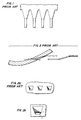
- Figs. l, 2, and 2a are drawings of the prior art which correspond to Figs. 4, 6, and 6a, respectively, of U.S. Patent No. 4,l97,443.
- Fig. 2b shows the actual shape of a passage formed using the electrode shown in Figs. l and 2.
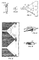
- Fig. 3 is a hollow turbine blade, partly broken away, which is machined with an electrode embodying the present invention.
- Fig. 4 is an enlarged sectional view taken along the line 4-4 of Fig. 3.
- Fig. 5 is a view taken generally in the direction 5-5 of Fig. 4.
- Fig. 6 is a sectional view taken along the line 6-6 of Fig. 4.
- Fig. l0 is a sectional view taken generally along the line l0-l0 of Fig. 8.
- Fig. 11 is a view taken generally in the direction 11-11 of Fig. 7.
- Fig. l2 shows a portion of a piece of sheetmetal which is cut along the lines drawn thereon to produce a blank from which the electrode of Figs. 7-11 is formed.
- Fig. l3 is a perspective view showing an alternate embodiment of the electrode of the present invention.
- a blade l00 for use in the turbine section of a gas turbine engine is shown in side elevation view.
- the blade 100 includes a hollow airfoil l02 which extends in a spanwise or longitudinal direction from a root l04.
- a platform 106 is disposed at the base of the airfoil 102.
- the airfoil 102 is hollow and includes a plurality of film cooling passages l08 extending through the airfoil wall 110 (Fig. 4). For purposes of simplicity and clarity, only two longitudinally extending rows of passages l08 are shown in the drawing.
- a typical turbine section airfoil will have many more rows of passages, some rows being on the pressure side of the airfoil, and others being disposed along the leading edge and suction side of the airfoil.
- the passages l08 communicate with a compartment within the airfoil, which compartment is adapted to receive pressurized coolant fluid through channels 112 through the root 104, which channels communicate with the compartments.
- the pressurized fluid flows out of the compartments through the wall 110 via the passages l08, cooling the wall and preferably forming a film of coolant on the outer surface 114 of the airfoil downstream (i.e., in the direction of the mainstream hot gas flow over the airfoil surface) of the passage outlet.
- the outlet l32 of the metering section is coincident with the inlet of the diffusing section.
- the diffusing section comprises a pair of spaced apart, facing side walls l34, l36 interconnected by a pair of facing, spaced apart, end walls l38, l40.
- the side walls and end walls of the diffusing section intersect the outer surface 114 of the wall 110 to define an outlet 141.
- the side surface 134 of the diffusing section 118 is coplanar with the side surface 120 of the metering section 116.
- the side surface 136 of the diffusing section 118 diverges from the opposing side surface l34 toward the outlet l40 at an angle herein designated by the letter A.
- the end surfaces l38, l40 diverge from each other by an included angle B.
- Figs. 7-11 show a sheet metal electrode 200 for electro-discharge machining passages having a shape like that of the passages l08.
- Each electrode includes a plurality of teeth 202.
- Each tooth 202 includes a front section 206, a middle section 208, and a rear section 2l0.
- the rear sections 2l0 of the teeth 202 are coextensive and form a common base (hereinafter also referred to by the reference numeral 2l0) for the electrode 200 which, during use, is secured to a tool holder (not shown).
- the holder is connected to a negative terminal of a DC power source; and the airfoil l02 into which the passages are to be machined is connected to a positive terminal.
- the front section 206 is flat and elongated in what is herein referred to as the longitudinal direction, which is along an axis 2l2 of the tooth 202.
- the front section 206 has a constant cross-sectional area perpendicular to the longitudinal and includes an upper surface 2l4, the upper surface having a pair of straight, parallel side edges 2l8 extending in the longitudinal direction, and a rear edge 220 interconnecting the side edges.
- the middle section 208 includes a flat upper surface 222 lying in a plane which forms an obtuse interior angle E with the upper surface 2l4 and an acute angle C with an extension of the plane of the upper surface 2l4.
- the upper surface 222 has a forward edge coincident with and the same length as the rear edge 220 of the upper surface 2l4.
- the upper surface 222 also has a pair of side edges 224 on opposite sides of the axis 2l2, each edge diverging therefrom by an angle herein designated by the letter D (Fig. 11).
- Each edge 224 also includes a side wall 226 integral therewith along the length of the edge, the side walls, in this preferred embodiment, being perpendicular to the plane of both upper surfaces 2l4, 222.
- Each side wall includes an outer surface 228 facing away from the axis 2l2, and a straight lower edge 230 extending rearwardly from the rear edge 220 of the front section to the base 2l0.
- the outwardly facing surfaces 228 of the side walls 226 of each electrode tooth form the end surfaces 138, 140 of the diffusing section 118 of the coolant passage 108.
- the angle D (Fig. 11) is one-half the desired included angle B of the coolant passage.
- the upper surface 222 of the middle section 208 forms the side surface 136, of the diffusing section 118; and the lower edges 230 of the side walls 226, along with the lower surface 216 of the front section 206, form the side surface 134 of the diffusing section 118.
- the angle C of each electrode tooth is selected to be substantially the angle A of the coolant passage.
Landscapes
- Engineering & Computer Science (AREA)
- Mechanical Engineering (AREA)
- Physics & Mathematics (AREA)
- Thermal Sciences (AREA)
- Manufacturing & Machinery (AREA)
- Electrical Discharge Machining, Electrochemical Machining, And Combined Machining (AREA)
- Turbine Rotor Nozzle Sealing (AREA)
Claims (6)
- Elektrode (200) zum Einbau in eine elektrische Entladungsmaschine, wobei die Elektrode (200) wenigstens einen sich in Längsrichtung erstreckenden Zahn (202) aufweist, der eine sich in Längsrichtung erstreckende Achse (212) hat, wobei der Zahn (202) aus einem einzelnen Stück Blech gebildet ist und in Reihe einen vorderen Abschnitt (206), einen mittleren Abschnitt (208) und einen hinteren Abschnitt (210) aufweist, wobei der vordere Abschnitt (206) parallele untere und obere Oberflächen (216, 214) aufweist, wobei die obere Oberfläche (214) in einer ersten Ebene liegt und zwei gerade, parallele Seitenränder (218) hat, welche sich in der Längsrichtung erstrecken, und einen hinteren Rand (220), der die Seitenränder (218) miteinander verbindet; wobei der mittlere Abschnitt (208) eine obere Oberfläche (222;3O2) hat, die in einer zweiten Ebene liegt, welche einen inneren stumpfen Winkel (E) mit der ersten Ebene und einen spitzen Winkel (c) mit einem Fortsatz der ersten Ebene bildet, wobei die obere Oberfläche (222;3O2) des mittleren Aufschnitts (208) einen vorderen Rand hat, wobei der vordere Rand mit dem hinteren Rand (220) des vorderen Abschnitts (206) zusammenfällt und dieselbe Länge wie dieser hat, und Seitenränder (224) in der Ebene der oberen Oberfläche, die sich von dem vorderen Rand aus auf entgegengesetzten Seiten der sich in Längsrichtung erstreckenden Achse (212) nach hinten erstrecken, wobei wenigstens einer der Seitenränder (224) des mittleren Abschnitts von der Achse (212) weg divergiert;
wobei die Seitenränder (224) des mittleren Abschnitts (208) jeweils eine mit ihnen einstückig ausgebildete Seitenwand (226;3OO) über der Länge des Seitenrands (224) des mittleren Abschnitts haben, wobei jede Seitenwand (226;300) eine Oberfläche (228) hat, die nach außen weg von der Achse (212) gerichtet ist, wobei jede Seitenwand (226;3OO) einen geraden unteren Rand (230) hat, der in der Ebene der unteren Oberfläche (216) des vorderen Abschnitts (206) liegt und sich von dem vorderen Abschnitt (206) aus nach hinten erstreckt; und
wobei sich der hintere Abschnitt (210) von dem mittleren Abschnitt (208) aus nach hinten erstreckt und an eine Stromquelle anschließbar ist. - Elektrode nach Anspruch 1, wobei beide Seitenränder (224) des mittleren Abschnitts von der Achse (212) weg divergieren.
- Elektrode nach Anspruch 1, wobei der hintere Abschnitt (210) im wesentlichen parallel zu der oberen Oberfläche (214) des vorderen Abschnitts (206) ist.
- Elektrode nach Anspruch 1, wobei die Seitenwände (226;300) zu der oberen Oberfläche (302) des mittleren Abschnitts (208) rechtwinkelig sind.
- Elektrode nach Anspruch 1, wobei jede Seitenwand (300) mit der oberen Oberfläche (302) des mittleren Abschnitts (208) ein glatte Kurve bildet.
- Elektrode nach Anspruch 5, wobei die glatte Kurve die Form eines Kegels bildet.
Applications Claiming Priority (2)
| Application Number | Priority Date | Filing Date | Title |
|---|---|---|---|
| US06/812,096 US4650949A (en) | 1985-12-23 | 1985-12-23 | Electrode for electrical discharge machining film cooling passages in an airfoil |
| US812096 | 1985-12-23 |
Publications (3)
| Publication Number | Publication Date |
|---|---|
| EP0227581A2 EP0227581A2 (de) | 1987-07-01 |
| EP0227581A3 EP0227581A3 (en) | 1989-04-26 |
| EP0227581B1 true EP0227581B1 (de) | 1991-06-12 |
Family
ID=25208485
Family Applications (1)
| Application Number | Title | Priority Date | Filing Date |
|---|---|---|---|
| EP86630197A Expired - Lifetime EP0227581B1 (de) | 1985-12-23 | 1986-12-18 | Elektrode zur Herstellung von Kühlkanälen |
Country Status (8)
| Country | Link |
|---|---|
| US (1) | US4650949A (de) |
| EP (1) | EP0227581B1 (de) |
| JP (1) | JP2520616B2 (de) |
| CN (1) | CN1006449B (de) |
| AU (1) | AU592842B2 (de) |
| CA (1) | CA1261005A (de) |
| DE (2) | DE3679794D1 (de) |
| IL (1) | IL81064A (de) |
Cited By (1)
| Publication number | Priority date | Publication date | Assignee | Title |
|---|---|---|---|---|
| DE102004051859A1 (de) * | 2004-10-26 | 2006-04-27 | Volkswagen Ag | Gehäuse und Verfahren zur Erzeugung von Kühlstrukturen für ein Gehäuse |
Families Citing this family (37)
| Publication number | Priority date | Publication date | Assignee | Title |
|---|---|---|---|---|
| US4762464A (en) * | 1986-11-13 | 1988-08-09 | Chromalloy Gas Turbine Corporation | Airfoil with diffused cooling holes and method and apparatus for making the same |
| US4808785A (en) * | 1986-11-13 | 1989-02-28 | Chromalloy Gas Turbine Corporation | Method and apparatus for making diffused cooling holes in an airfoil |
| US4819325A (en) * | 1987-06-01 | 1989-04-11 | Technical Manufacturing Systems, Inc. | Method of forming electro-discharge machining electrode |
| US4922076A (en) * | 1987-06-01 | 1990-05-01 | Technical Manufacturing Systems, Inc. | Electro-discharge machining electrode |
| US5192192A (en) * | 1990-11-28 | 1993-03-09 | The United States Of America As Represented By The Secretary Of The Air Force | Turbine engine foil cap |
| US5813835A (en) * | 1991-08-19 | 1998-09-29 | The United States Of America As Represented By The Secretary Of The Air Force | Air-cooled turbine blade |
| US5368441A (en) * | 1992-11-24 | 1994-11-29 | United Technologies Corporation | Turbine airfoil including diffusing trailing edge pedestals |
| US5313038A (en) * | 1992-12-22 | 1994-05-17 | United Technologies Corporation | EDM drilling of low angle holes |
| US5605639A (en) * | 1993-12-21 | 1997-02-25 | United Technologies Corporation | Method of producing diffusion holes in turbine components by a multiple piece electrode |
| US5418345A (en) * | 1994-02-28 | 1995-05-23 | United Technologies Corporation | Method for forming shaped passages |
| US5637239A (en) * | 1995-03-31 | 1997-06-10 | United Technologies Corporation | Curved electrode and method for electrical discharge machining curved cooling holes |
| FR2820066B1 (fr) * | 2001-02-01 | 2003-03-07 | Snecma Moteurs | Dispositif de centrage et de percage de formes et de trous cylindriques |
| US6897401B2 (en) * | 2003-07-31 | 2005-05-24 | United Technologies Corporation | Non-separating diffuser for holes produced by a two step process |
| US7328580B2 (en) * | 2004-06-23 | 2008-02-12 | General Electric Company | Chevron film cooled wall |
| US7374401B2 (en) | 2005-03-01 | 2008-05-20 | General Electric Company | Bell-shaped fan cooling holes for turbine airfoil |
| WO2007006619A1 (en) * | 2005-07-12 | 2007-01-18 | Siemens Aktiengesellschaft | Film-cooled component, in particular a turbine blade and method for manufacturing a turbine blade |
| JP4931507B2 (ja) * | 2005-07-26 | 2012-05-16 | スネクマ | 壁内に形成された冷却流路 |
| US7789625B2 (en) * | 2007-05-07 | 2010-09-07 | Siemens Energy, Inc. | Turbine airfoil with enhanced cooling |
| US20100008759A1 (en) * | 2008-07-10 | 2010-01-14 | General Electric Company | Methods and apparatuses for providing film cooling to turbine components |
| US8057182B2 (en) * | 2008-11-21 | 2011-11-15 | General Electric Company | Metered cooling slots for turbine blades |
| US8168912B1 (en) | 2009-02-19 | 2012-05-01 | Florida Turbine Technologies, Inc. | Electrode for shaped film cooling hole |
| US8742279B2 (en) * | 2010-02-01 | 2014-06-03 | United Technologies Corporation | Method of creating an airfoil trench and a plurality of cooling holes within the trench |
| US8905713B2 (en) | 2010-05-28 | 2014-12-09 | General Electric Company | Articles which include chevron film cooling holes, and related processes |
| US9126278B2 (en) | 2012-08-15 | 2015-09-08 | Siemens Energy, Inc. | Template for forming cooling passages in a turbine engine component |
| US20160090843A1 (en) * | 2014-09-30 | 2016-03-31 | General Electric Company | Turbine components with stepped apertures |
| CN106031955A (zh) * | 2015-03-19 | 2016-10-19 | 苏州汉扬精密电子有限公司 | 电极结构 |
| US20160298462A1 (en) * | 2015-04-09 | 2016-10-13 | United Technologies Corporation | Cooling passages for a gas turbine engine component |
| CN105171158B (zh) * | 2015-10-10 | 2017-11-14 | 贵阳中航动力精密铸造有限公司 | 一种涡轮导向叶片锥形气膜孔加工工艺 |
| KR101853550B1 (ko) * | 2016-08-22 | 2018-04-30 | 두산중공업 주식회사 | 가스 터빈 블레이드 |
| US10774683B2 (en) | 2017-04-12 | 2020-09-15 | General Electric Company | Hole drilling elastically deformed superalloy turbine blade |
| US10220461B2 (en) | 2017-04-12 | 2019-03-05 | General Electric Company | Hole drilling elastically deformed superalloy turbine blade |
| CN107725115B (zh) * | 2017-04-28 | 2019-07-30 | 中国航发湖南动力机械研究所 | 航空发动机热端部件的翼型气膜孔及电极 |
| US10773344B2 (en) | 2017-06-16 | 2020-09-15 | Raytheon Technologies Corporation | Systems and methods for manufacturing film cooling hole diffuser portion |
| EP3450682A1 (de) * | 2017-08-30 | 2019-03-06 | Siemens Aktiengesellschaft | Wand eines bauteils für heissgas und zugehöriges bauteil |
| US10570747B2 (en) * | 2017-10-02 | 2020-02-25 | DOOSAN Heavy Industries Construction Co., LTD | Enhanced film cooling system |
| CN113224893B (zh) * | 2020-01-21 | 2023-03-28 | 上海电力大学 | 一种车载用永磁同步电机冷却水道优化方法 |
| CN112518058A (zh) * | 2020-12-23 | 2021-03-19 | 贵阳航发精密铸造有限公司 | 一种整体电极及加工整体电极的方法 |
Family Cites Families (22)
| Publication number | Priority date | Publication date | Assignee | Title |
|---|---|---|---|---|
| CA733484A (en) * | 1966-05-03 | General Electric Company | Cathode tool for electrical machining | |
| US534314A (en) * | 1895-02-19 | Fall-rope carrier | ||
| GB814202A (en) * | 1956-04-18 | 1959-06-03 | Birmingham Small Arms Co Ltd | Improvements in or relating to the simultaneous spark machining of a plurality of workpieces |
| NL213363A (de) * | 1955-12-30 | |||
| BE562501A (de) * | 1956-11-20 | |||
| US2972182A (en) * | 1957-02-22 | 1961-02-21 | Rolls Royce | Turbine and compressor blades |
| GB856674A (en) * | 1958-06-18 | 1960-12-21 | Rolls Royce | Blades for gas turbine engines |
| NL249220A (de) * | 1959-03-09 | |||
| FR1269229A (fr) * | 1960-06-29 | 1961-08-11 | Const Guinard | Procédé pour la fabrication de tamis |
| US3316626A (en) * | 1964-10-26 | 1967-05-02 | J F Fredericks Tool Company In | Method of making an airfoil shaped electrode |
| US3527543A (en) * | 1965-08-26 | 1970-09-08 | Gen Electric | Cooling of structural members particularly for gas turbine engines |
| CH460975A (fr) * | 1967-05-05 | 1968-08-15 | Charmilles Sa Ateliers | Dispositif d'amenée de courant à une pièce à usiner par usinage électro-chimique |
| GB1209692A (en) * | 1968-05-14 | 1970-10-21 | Rolls Royce | Method and apparatus for the spark-machining of workpieces and a spark-machining electrode for use therein |
| BE754171A (fr) * | 1969-10-18 | 1970-12-31 | Glanzstoff Ag | Procede pour la fabrication d'electrodes pour l'obtention electroerosive de perforations profilees de filage |
| US3803009A (en) * | 1970-12-28 | 1974-04-09 | Hitachi Ltd | Method of producing a unitary turbine wheel having twisted blades by electrolytic fabrication |
| US3963894A (en) * | 1974-01-24 | 1976-06-15 | Chromalloy American Corporation | Turbine-nozzle manufacturing apparatus |
| US3981786A (en) | 1974-12-19 | 1976-09-21 | United Technologies Corporation | ECM and EDM tooling for producing holes in airfoil trailing edges |
| US4096371A (en) * | 1976-07-06 | 1978-06-20 | Lozon Garnet W | Method of and apparatus for electrical discharge machining |
| US4197443A (en) * | 1977-09-19 | 1980-04-08 | General Electric Company | Method and apparatus for forming diffused cooling holes in an airfoil |
| US4256555A (en) * | 1978-05-30 | 1981-03-17 | Rolls Royce Limited | Electro-chemical-machining of aerofoil blades |
| US4217190A (en) * | 1979-06-20 | 1980-08-12 | United Technologies Corporation | Method and apparatus for electrochemically finishing airfoil edges |
| FR2491549B1 (fr) * | 1980-10-08 | 1985-07-05 | Snecma | Dispositif de refroidissement d'une turbine a gaz, par prelevement d'air au niveau du compresseur |
-
1985
- 1985-12-23 US US06/812,096 patent/US4650949A/en not_active Expired - Lifetime
-
1986
- 1986-12-16 AU AU66679/86A patent/AU592842B2/en not_active Ceased
- 1986-12-18 DE DE8686630197T patent/DE3679794D1/de not_active Expired - Lifetime
- 1986-12-18 DE DE198686630197T patent/DE227581T1/de active Pending
- 1986-12-18 EP EP86630197A patent/EP0227581B1/de not_active Expired - Lifetime
- 1986-12-22 CA CA000526018A patent/CA1261005A/en not_active Expired
- 1986-12-22 IL IL81064A patent/IL81064A/xx not_active IP Right Cessation
- 1986-12-23 JP JP61307577A patent/JP2520616B2/ja not_active Expired - Fee Related
- 1986-12-23 CN CN86108819A patent/CN1006449B/zh not_active Expired
Cited By (2)
| Publication number | Priority date | Publication date | Assignee | Title |
|---|---|---|---|---|
| DE102004051859A1 (de) * | 2004-10-26 | 2006-04-27 | Volkswagen Ag | Gehäuse und Verfahren zur Erzeugung von Kühlstrukturen für ein Gehäuse |
| DE102004051859B4 (de) * | 2004-10-26 | 2017-02-23 | Volkswagen Ag | Gehäuse und Verfahren zur Erzeugung von Kühlstrukturen für ein Gehäuse |
Also Published As
| Publication number | Publication date |
|---|---|
| IL81064A0 (en) | 1987-03-31 |
| JP2520616B2 (ja) | 1996-07-31 |
| EP0227581A3 (en) | 1989-04-26 |
| US4650949A (en) | 1987-03-17 |
| AU592842B2 (en) | 1990-01-25 |
| DE3679794D1 (de) | 1991-07-18 |
| JPS62228328A (ja) | 1987-10-07 |
| EP0227581A2 (de) | 1987-07-01 |
| CA1261005A (en) | 1989-09-26 |
| IL81064A (en) | 1991-06-10 |
| CN1006449B (zh) | 1990-01-17 |
| CN86108819A (zh) | 1987-07-08 |
| AU6667986A (en) | 1987-06-25 |
| DE227581T1 (de) | 1987-12-17 |
Similar Documents
| Publication | Publication Date | Title |
|---|---|---|
| EP0227581B1 (de) | Elektrode zur Herstellung von Kühlkanälen | |
| CA1273583A (en) | Coolant passages with full coverage film cooling slot | |
| EP0230204B1 (de) | Convergent-divergenter Kanal zur Filmkühlung | |
| EP0227578B1 (de) | Kühlschlitz mit Zumessöffnung | |
| EP0227582B1 (de) | Kühlkanäle mit Stufendiffusor | |
| CA1262689A (en) | Film cooling passages with curved corners | |
| EP0227580B1 (de) | Kühlkanal für hohle gegossene Turbinenschaufeln | |
| EP0648918B1 (de) | Kanalmündung zur Filmkühlung dünner Wände | |
| US4672727A (en) | Method of fabricating film cooling slot in a hollow airfoil | |
| EP1898051B1 (de) | Gasturbinenschaufel mit Kühlung der Leitkante | |
| US8057181B1 (en) | Multiple expansion film cooling hole for turbine airfoil | |
| EP0375175B1 (de) | Gekühlte Bauteile für Turbomaschinen | |
| US5458461A (en) | Film cooled slotted wall | |
| CA2460705C (en) | Non-serapating diffuser for holes produced by a two-step process | |
| DE69923914T2 (de) | Strömungsmaschinenschaufel mit aparter Kühlung der Anströmkante | |
| EP0326508B1 (de) | Fabrikationsmethode einer luftgekühlten Gasturbinenschaufel | |
| JPS59136502A (ja) | 冷却ガスタ−ビンエンジンエ−ロフオイル | |
| GB2506092A (en) | Turbine airfoil suction aided film cooling means |
Legal Events
| Date | Code | Title | Description |
|---|---|---|---|
| PUAI | Public reference made under article 153(3) epc to a published international application that has entered the european phase |
Free format text: ORIGINAL CODE: 0009012 |
|
| AK | Designated contracting states |
Kind code of ref document: A2 Designated state(s): DE FR GB |
|
| EL | Fr: translation of claims filed | ||
| DET | De: translation of patent claims | ||
| PUAL | Search report despatched |
Free format text: ORIGINAL CODE: 0009013 |
|
| AK | Designated contracting states |
Kind code of ref document: A3 Designated state(s): DE FR GB |
|
| 17P | Request for examination filed |
Effective date: 19891004 |
|
| 17Q | First examination report despatched |
Effective date: 19900827 |
|
| GRAA | (expected) grant |
Free format text: ORIGINAL CODE: 0009210 |
|
| AK | Designated contracting states |
Kind code of ref document: B1 Designated state(s): DE FR GB |
|
| ET | Fr: translation filed | ||
| REF | Corresponds to: |
Ref document number: 3679794 Country of ref document: DE Date of ref document: 19910718 |
|
| PLBE | No opposition filed within time limit |
Free format text: ORIGINAL CODE: 0009261 |
|
| STAA | Information on the status of an ep patent application or granted ep patent |
Free format text: STATUS: NO OPPOSITION FILED WITHIN TIME LIMIT |
|
| 26N | No opposition filed | ||
| REG | Reference to a national code |
Ref country code: GB Ref legal event code: IF02 |
|
| PGFP | Annual fee paid to national office [announced via postgrant information from national office to epo] |
Ref country code: GB Payment date: 20051104 Year of fee payment: 20 |
|
| PGFP | Annual fee paid to national office [announced via postgrant information from national office to epo] |
Ref country code: FR Payment date: 20051201 Year of fee payment: 20 |
|
| PGFP | Annual fee paid to national office [announced via postgrant information from national office to epo] |
Ref country code: DE Payment date: 20051230 Year of fee payment: 20 |
|
| PG25 | Lapsed in a contracting state [announced via postgrant information from national office to epo] |
Ref country code: GB Free format text: LAPSE BECAUSE OF EXPIRATION OF PROTECTION Effective date: 20061217 |
|
| REG | Reference to a national code |
Ref country code: GB Ref legal event code: PE20 |