EP0227680B1 - Flüssigkeitsdüse - Google Patents
Flüssigkeitsdüse Download PDFInfo
- Publication number
- EP0227680B1 EP0227680B1 EP85905097A EP85905097A EP0227680B1 EP 0227680 B1 EP0227680 B1 EP 0227680B1 EP 85905097 A EP85905097 A EP 85905097A EP 85905097 A EP85905097 A EP 85905097A EP 0227680 B1 EP0227680 B1 EP 0227680B1
- Authority
- EP
- European Patent Office
- Prior art keywords
- channel
- vanes
- channels
- communicating chamber
- conduit
- Prior art date
- Legal status (The legal status is an assumption and is not a legal conclusion. Google has not performed a legal analysis and makes no representation as to the accuracy of the status listed.)
- Expired
Links
Images


Classifications
-
- A—HUMAN NECESSITIES
- A62—LIFE-SAVING; FIRE-FIGHTING
- A62C—FIRE-FIGHTING
- A62C31/00—Delivery of fire-extinguishing material
- A62C31/02—Nozzles specially adapted for fire-extinguishing
- A62C31/24—Nozzles specially adapted for fire-extinguishing attached to ladders, poles, towers, or other structures with or without rotary heads
-
- B—PERFORMING OPERATIONS; TRANSPORTING
- B05—SPRAYING OR ATOMISING IN GENERAL; APPLYING FLUENT MATERIALS TO SURFACES, IN GENERAL
- B05B—SPRAYING APPARATUS; ATOMISING APPARATUS; NOZZLES
- B05B1/00—Nozzles, spray heads or other outlets, with or without auxiliary devices such as valves, heating means
- B05B1/02—Nozzles, spray heads or other outlets, with or without auxiliary devices such as valves, heating means designed to produce a jet, spray, or other discharge of particular shape or nature, e.g. in single drops, or having an outlet of particular shape
-
- B—PERFORMING OPERATIONS; TRANSPORTING
- B05—SPRAYING OR ATOMISING IN GENERAL; APPLYING FLUENT MATERIALS TO SURFACES, IN GENERAL
- B05B—SPRAYING APPARATUS; ATOMISING APPARATUS; NOZZLES
- B05B1/00—Nozzles, spray heads or other outlets, with or without auxiliary devices such as valves, heating means
- B05B1/34—Nozzles, spray heads or other outlets, with or without auxiliary devices such as valves, heating means designed to influence the nature of flow of the liquid or other fluent material, e.g. to produce swirl
- B05B1/3402—Nozzles, spray heads or other outlets, with or without auxiliary devices such as valves, heating means designed to influence the nature of flow of the liquid or other fluent material, e.g. to produce swirl to avoid or reduce turbulence, e.g. with fluid flow straightening means
Definitions
- This invention relates to a fluid flow device having two co-axial channels and a communicating chamber at one end of both channels through which fluid may flow from one channel to the other, reversing its axial direction of flow as it does so according to the preamble of Claim 1.
- Fluid enters the outer channel at two diametrically opposite locations, so that in flowing down the outer channel the fluid will possess tangential components of velocity and the axial velocity distribution around the axis of the channels will not be uniform.
- the present invention improves on WO 83/ 03768 by providing a fluid flow device as set out in Claim 1.
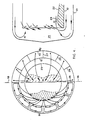
- the fluid flow device illustrated in Figures 1 and 2 comprises three concentric tubes 11, 12 and 13.
- the inner tube contains a straightener locating rod 14 connected to a straightener 15 located towards the downstream end of an inner annular channel 16 bounded by the middle conduit 12. This will be described later.
- An outer annular channel 17 is formed between the middle and outer conduits.
- the device is mounted so that the plane represented by Figure 1 is vertical and the device is movable within this vertical plane by rotation about a horizontal axis 18.
- Fluid for example water, enters the outer channel 17 from two diametrically opposite conduits 19 centred on the axis 18 and passes from right to left as seen in Figure 1 along the outer channel 17 to its left hand end as seen in Figure 1.
- the middle conduit 12 ends at a predetermined distance from the end of the outer conduit 13, and within this predetermined distance there is formed a communicating chamber 21 between the inner and outer channels 16 and 17.
- the outer channel 17 is of constant cross-section between the entry conduit 19 and the communicating chamber 21, but the inner channel 16 is formed with a throat at its left hand end by means of a diffuser 22 whose inner boundary has a quarter-circle portion from the left hand end of the middle conduit 12 to the minimum radius of the throat 23, after which the boundary tapers gently outwardly until it reaches the inner wall of the middle conduit 12, the inner channel 16 thereafter being of constant cross-section except for the straightener 15.
- a nozzle 24 is located at the downstream end of the inner channel 16, but this is not illustrated in detail.
- the purpose of the present apparatus is to provide non-turbulent flow at the nozzle 24 from fluid entering the device at the conduits 19.
- the conduits 19 are not uniformly distributed around the common axis of the conduits 11 to 13 and so there will be considerable tangential motion of fluid within the outer channel 17 which will lead to turbulence within the inner channel unless preventive measures are taken.
- These preventive measures are present in the form of vanes of four different types, 25 to 28.
- the vanes of each type are symmetrically arranged about the vertical centre line of Figure 2 and also about its horizontal centre line. The vanes are radial with respect to the common axis of the conduits 11 to 13 and the channel between adjacent vanes subtends an angle of 30° at this axis.
- Vanes 25 and 26 are similar. Both vanes extend continuously from a point adjacent the entry conduit 19 through the outer channel 17, the communicating chamber 21 and inner channel 16 to a point downstream of the throat 23. Each vane 25 and 26 forms a continuous and complete barrier between the outer conduit 13 and the mid conduit 12, and between the mid conduit 12 and the inner conduit 11. The vane 26 extends a slightly shorter distance than the vane 25 along the outer channel 17 from the communicating chamber 21 since the conduit 19 extends further along the channel 17 at the position of the vane 26 than the vane 25, and the vanes 25 and 26 are positioned to divide the outer channel 17 into separate longitudinal channels as soon as possible after the fluid leaves the conduit 19.
- the two vanes of type 27 lie on the vertical plane through the common axis of the conduits 11 to 13 and extends from the upstream end of the outer channel 17 to a position short of the downstream end of the channel 17 communicating with the chamber 21.
- the two vanes of type 28 extend from the junction of the conduit 19 with the channel 17 to a downstream boundary level with the downstream boundary of the vanes 27.
- vanes of type 27 and 28 do not extend within the communicating chamber 21 or the inner channel 16.
- the vanes 27 and 28 are thicker than the vanes of type 25 and 26 by a factor of about three.
- the straightener 15 comprises a plurality of separate flow channels extending parallel to the common axis of the conduits 11 to 13. These channels may be formed from a plurality of tubes secured together, or from a series of plates extending parallel to the common axis of the conduits and arranged in a grid pattern.
- the straightener 15 serves to reduce any turbulence which is still present in the inner channel in spite of the effect of the vanes 25 to 28.
- the thickness of the plates or tubes forming the straightener will form a partial blockage of the inner channel 16, and a blockage of less than 20° is acceptable, although a blockage of nearer 10° is preferable.
- the length of the straightener 15 is about ten times the width of an individual channel within the straightener.
- the straightener 15 is located at least one fifth of the diameter of conduit 12 from the nozzle and about half the diameter of conduit 12 from the tapering portion of the diffuser 22. Decreasing the size of the individual channels in the straightener 15 increases the blockage ratio since more of the straightener is taken up by channel walls and was found not to improve turbulence levels, probably because of the increased blockage. Increasing the length of the straightener 15 was found to give less uniform exit velocities whereas shorter lengths decreased the improvement in turbulence levels.
- the diffuser 22 varies the size of the inner channel 16, but there is no similar variation of the outer channel 17.
- the uniform outer channel was found to limit the build-up of retarded fluid within the inner tube, due to the delay in turning the fluid around the bend.
- the shape of the diffuser 22 was selected to give a ratio of the. maximum to minimum cross- sectional area of the inner channel 16 of 1.63.
- vanes of type 25 and type 26 and two each of vanes of type 27 and type 28 there are four each of vanes of type 25 and type 26 and two each of vanes of type 27 and type 28.
- the vanes of type 25 and 27 prevent any excessive build-up of retarded fluid within the inner tube.
- the vanes of type 27 and type 28 only extend in the outer channel 17 since they separate flow channels where the secondary flow tends to oppose rather than reinforce adverse build-up of retarded fluid.
- Figure 4 shows secondary flows at the communicating chamber 21 with the apparatus in the same orientation as Figure 3, the arrows H and L representing high ' and low velocity fluid respectively.
Landscapes
- Health & Medical Sciences (AREA)
- Public Health (AREA)
- Business, Economics & Management (AREA)
- Emergency Management (AREA)
- Physics & Mathematics (AREA)
- Fluid Mechanics (AREA)
- Pipe Accessories (AREA)
- Solid-Sorbent Or Filter-Aiding Compositions (AREA)
- Medicines Containing Material From Animals Or Micro-Organisms (AREA)
- Treatment Of Liquids With Adsorbents In General (AREA)
- Nozzles (AREA)
Claims (7)
Applications Claiming Priority (2)
| Application Number | Priority Date | Filing Date | Title |
|---|---|---|---|
| GB848426662A GB8426662D0 (en) | 1984-10-22 | 1984-10-22 | Fluid flow device |
| GB8426662 | 1984-10-22 |
Publications (2)
| Publication Number | Publication Date |
|---|---|
| EP0227680A1 EP0227680A1 (de) | 1987-07-08 |
| EP0227680B1 true EP0227680B1 (de) | 1988-12-28 |
Family
ID=10568550
Family Applications (1)
| Application Number | Title | Priority Date | Filing Date |
|---|---|---|---|
| EP85905097A Expired EP0227680B1 (de) | 1984-10-22 | 1985-10-22 | Flüssigkeitsdüse |
Country Status (7)
| Country | Link |
|---|---|
| US (1) | US4784183A (de) |
| EP (1) | EP0227680B1 (de) |
| JP (1) | JPS62501134A (de) |
| DE (1) | DE3566958D1 (de) |
| GB (1) | GB8426662D0 (de) |
| NO (1) | NO165383C (de) |
| WO (1) | WO1986002578A1 (de) |
Families Citing this family (2)
| Publication number | Priority date | Publication date | Assignee | Title |
|---|---|---|---|---|
| CA2988084C (en) | 2015-07-16 | 2019-11-05 | Halliburton Energy Services, Inc. | Particulate laden fluid vortex erosion mitigation |
| RU202165U1 (ru) * | 2020-11-02 | 2021-02-05 | Андрей Леонидович Душкин | Распылитель |
Family Cites Families (6)
| Publication number | Priority date | Publication date | Assignee | Title |
|---|---|---|---|---|
| GB191514104A (en) * | 1915-10-05 | 1916-01-27 | Ralph Machin | An Improved Lacquering or Painting Machine for Tins and similar closed Receptacles. |
| US1946945A (en) * | 1930-09-02 | 1934-02-13 | Universal Oil Prod Co | Return bend plug deflector |
| GB442186A (en) * | 1934-03-05 | 1936-02-04 | Junkers Flugzeugwerk Ag | Improvements in and relating to silencers for pulsating gaseous currents |
| SU151660A1 (ru) * | 1961-11-29 | 1961-11-30 | В.В. Трофимов | Пропорциональный делитель потока виноградной мезги |
| US4118173A (en) * | 1977-08-08 | 1978-10-03 | Samuel Lebidine | Unidirectional seal for flow passages |
| EP0120867B1 (de) * | 1982-05-04 | 1987-06-24 | The British Hydromechanics Research Association | Strahlrohr für feuerlöschgerät |
-
1984
- 1984-10-22 GB GB848426662A patent/GB8426662D0/en active Pending
-
1985
- 1985-10-22 DE DE8585905097T patent/DE3566958D1/de not_active Expired
- 1985-10-22 US US06/887,834 patent/US4784183A/en not_active Expired - Fee Related
- 1985-10-22 WO PCT/GB1985/000486 patent/WO1986002578A1/en not_active Ceased
- 1985-10-22 JP JP60504604A patent/JPS62501134A/ja active Pending
- 1985-10-22 EP EP85905097A patent/EP0227680B1/de not_active Expired
-
1986
- 1986-06-23 NO NO862517A patent/NO165383C/no unknown
Also Published As
| Publication number | Publication date |
|---|---|
| WO1986002578A1 (en) | 1986-05-09 |
| DE3566958D1 (en) | 1989-02-02 |
| NO165383B (no) | 1990-10-29 |
| NO862517L (no) | 1986-06-23 |
| GB8426662D0 (en) | 1984-11-28 |
| US4784183A (en) | 1988-11-15 |
| NO862517D0 (no) | 1986-06-23 |
| NO165383C (no) | 1991-02-06 |
| JPS62501134A (ja) | 1987-05-07 |
| EP0227680A1 (de) | 1987-07-08 |
Similar Documents
| Publication | Publication Date | Title |
|---|---|---|
| DE2818791C2 (de) | Axial durchströmter Zyklonabscheider | |
| SE448018B (sv) | Hogeffektsradialflekt | |
| EP0018840A1 (de) | Vorrichtung zur Abscheidung mitgerissener Feuchtigheit aus gesättigtem Dampf in einem Dampfzeuger einer Kernkraftanlage | |
| US4163719A (en) | Hydrocyclone separator arrangement | |
| US4130017A (en) | Flow rate measuring device | |
| EP0227680B1 (de) | Flüssigkeitsdüse | |
| US4878785A (en) | Abrasive fluid flow | |
| US4366056A (en) | Filter having a fixed strainer | |
| SU901680A1 (ru) | Устройство дл равномерного распределени скоростей потока текучей среды | |
| US4233160A (en) | Hydrocyclone separator arrangement | |
| DE2747912C2 (de) | Hydrozyklonvorrichtung | |
| EP0234224B1 (de) | Wasservorabscheider für Turbinenabdampf | |
| DE19648583C1 (de) | Wirkdruckgeber eines Durchflußmessers | |
| DE1607660A1 (de) | Zyklon mit axialem Gaseintritt | |
| SU1320494A1 (ru) | Отсасывающа труба гидротурбины | |
| JPS5915006B2 (ja) | 流体混合装置 | |
| US4655090A (en) | Turbine flowmeter for fluids | |
| DE2513991C3 (de) | Vorrichtung zum Abtrennen von festen und flüssigen Teilchen aus strömenden Gasen durch Zentrifugalkraft | |
| EP0244335B1 (de) | Diffusor | |
| AT383052B (de) | Einrichtung zum abscheiden von feststoffen aus gasen | |
| RU2140317C1 (ru) | Центробежный сепарационный элемент | |
| DE651094C (de) | Fliehkraftstaubabscheider | |
| DE1285960B (de) | Zulaufeinrichtung fuer Kaplan- und Francisturbinen | |
| RU98116069A (ru) | Датчик активного давления для расходомера | |
| SU1055191A1 (ru) | Водосброс |
Legal Events
| Date | Code | Title | Description |
|---|---|---|---|
| PUAI | Public reference made under article 153(3) epc to a published international application that has entered the european phase |
Free format text: ORIGINAL CODE: 0009012 |
|
| 17P | Request for examination filed |
Effective date: 19870416 |
|
| AK | Designated contracting states |
Kind code of ref document: A1 Designated state(s): BE DE FR GB NL SE |
|
| 17Q | First examination report despatched |
Effective date: 19871103 |
|
| GRAA | (expected) grant |
Free format text: ORIGINAL CODE: 0009210 |
|
| AK | Designated contracting states |
Kind code of ref document: B1 Designated state(s): BE DE FR GB NL SE |
|
| REF | Corresponds to: |
Ref document number: 3566958 Country of ref document: DE Date of ref document: 19890202 |
|
| ET | Fr: translation filed | ||
| PLBE | No opposition filed within time limit |
Free format text: ORIGINAL CODE: 0009261 |
|
| STAA | Information on the status of an ep patent application or granted ep patent |
Free format text: STATUS: NO OPPOSITION FILED WITHIN TIME LIMIT |
|
| 26N | No opposition filed | ||
| PGFP | Annual fee paid to national office [announced via postgrant information from national office to epo] |
Ref country code: FR Payment date: 19931011 Year of fee payment: 9 |
|
| PGFP | Annual fee paid to national office [announced via postgrant information from national office to epo] |
Ref country code: GB Payment date: 19931012 Year of fee payment: 9 |
|
| PGFP | Annual fee paid to national office [announced via postgrant information from national office to epo] |
Ref country code: SE Payment date: 19931015 Year of fee payment: 9 |
|
| PGFP | Annual fee paid to national office [announced via postgrant information from national office to epo] |
Ref country code: DE Payment date: 19931021 Year of fee payment: 9 |
|
| PGFP | Annual fee paid to national office [announced via postgrant information from national office to epo] |
Ref country code: NL Payment date: 19931031 Year of fee payment: 9 |
|
| PGFP | Annual fee paid to national office [announced via postgrant information from national office to epo] |
Ref country code: BE Payment date: 19931130 Year of fee payment: 9 |
|
| PG25 | Lapsed in a contracting state [announced via postgrant information from national office to epo] |
Ref country code: GB Effective date: 19941022 |
|
| PG25 | Lapsed in a contracting state [announced via postgrant information from national office to epo] |
Ref country code: SE Effective date: 19941023 |
|
| PG25 | Lapsed in a contracting state [announced via postgrant information from national office to epo] |
Ref country code: BE Effective date: 19941031 |
|
| EAL | Se: european patent in force in sweden |
Ref document number: 85905097.3 |
|
| BERE | Be: lapsed |
Owner name: THE BRITISH HYDROMECHANICS RESEARCH ASSOCIATION Effective date: 19941031 |
|
| PG25 | Lapsed in a contracting state [announced via postgrant information from national office to epo] |
Ref country code: NL Effective date: 19950501 |
|
| NLV4 | Nl: lapsed or anulled due to non-payment of the annual fee | ||
| GBPC | Gb: european patent ceased through non-payment of renewal fee |
Effective date: 19941022 |
|
| PG25 | Lapsed in a contracting state [announced via postgrant information from national office to epo] |
Ref country code: FR Effective date: 19950630 |
|
| PG25 | Lapsed in a contracting state [announced via postgrant information from national office to epo] |
Ref country code: DE Effective date: 19950701 |
|
| EUG | Se: european patent has lapsed |
Ref document number: 85905097.3 |
|
| REG | Reference to a national code |
Ref country code: FR Ref legal event code: ST |