EP0227760B1 - Verfahren und werkzeug zum lochstanzen von gipsplatten - Google Patents
Verfahren und werkzeug zum lochstanzen von gipsplatten Download PDFInfo
- Publication number
- EP0227760B1 EP0227760B1 EP86904115A EP86904115A EP0227760B1 EP 0227760 B1 EP0227760 B1 EP 0227760B1 EP 86904115 A EP86904115 A EP 86904115A EP 86904115 A EP86904115 A EP 86904115A EP 0227760 B1 EP0227760 B1 EP 0227760B1
- Authority
- EP
- European Patent Office
- Prior art keywords
- holes
- punches
- slits
- blade
- punching
- Prior art date
- Legal status (The legal status is an assumption and is not a legal conclusion. Google has not performed a legal analysis and makes no representation as to the accuracy of the status listed.)
- Expired - Lifetime
Links
Images


Classifications
-
- B—PERFORMING OPERATIONS; TRANSPORTING
- B26—HAND CUTTING TOOLS; CUTTING; SEVERING
- B26F—PERFORATING; PUNCHING; CUTTING-OUT; STAMPING-OUT; SEVERING BY MEANS OTHER THAN CUTTING
- B26F1/00—Perforating; Punching; Cutting-out; Stamping-out; Apparatus therefor
- B26F1/02—Perforating by punching, e.g. with relatively-reciprocating punch and bed
-
- B—PERFORMING OPERATIONS; TRANSPORTING
- B26—HAND CUTTING TOOLS; CUTTING; SEVERING
- B26F—PERFORATING; PUNCHING; CUTTING-OUT; STAMPING-OUT; SEVERING BY MEANS OTHER THAN CUTTING
- B26F1/00—Perforating; Punching; Cutting-out; Stamping-out; Apparatus therefor
- B26F1/02—Perforating by punching, e.g. with relatively-reciprocating punch and bed
- B26F1/14—Punching tools; Punching dies
-
- B—PERFORMING OPERATIONS; TRANSPORTING
- B28—WORKING CEMENT, CLAY, OR STONE
- B28D—WORKING STONE OR STONE-LIKE MATERIALS
- B28D1/00—Working stone or stone-like materials, e.g. brick, concrete or glass, not provided for elsewhere; Machines, devices, tools therefor
- B28D1/22—Working stone or stone-like materials, e.g. brick, concrete or glass, not provided for elsewhere; Machines, devices, tools therefor by cutting, e.g. incising
- B28D1/222—Working stone or stone-like materials, e.g. brick, concrete or glass, not provided for elsewhere; Machines, devices, tools therefor by cutting, e.g. incising by pressing, e.g. presses
-
- Y—GENERAL TAGGING OF NEW TECHNOLOGICAL DEVELOPMENTS; GENERAL TAGGING OF CROSS-SECTIONAL TECHNOLOGIES SPANNING OVER SEVERAL SECTIONS OF THE IPC; TECHNICAL SUBJECTS COVERED BY FORMER USPC CROSS-REFERENCE ART COLLECTIONS [XRACs] AND DIGESTS
- Y10—TECHNICAL SUBJECTS COVERED BY FORMER USPC
- Y10T—TECHNICAL SUBJECTS COVERED BY FORMER US CLASSIFICATION
- Y10T83/00—Cutting
- Y10T83/869—Means to drive or to guide tool
- Y10T83/8821—With simple rectilinear reciprocating motion only
- Y10T83/8828—Plural tools with same drive means
- Y10T83/8831—Plural distinct cutting edges on same support
- Y10T83/8834—Successively acting
-
- Y—GENERAL TAGGING OF NEW TECHNOLOGICAL DEVELOPMENTS; GENERAL TAGGING OF CROSS-SECTIONAL TECHNOLOGIES SPANNING OVER SEVERAL SECTIONS OF THE IPC; TECHNICAL SUBJECTS COVERED BY FORMER USPC CROSS-REFERENCE ART COLLECTIONS [XRACs] AND DIGESTS
- Y10—TECHNICAL SUBJECTS COVERED BY FORMER USPC
- Y10T—TECHNICAL SUBJECTS COVERED BY FORMER US CLASSIFICATION
- Y10T83/00—Cutting
- Y10T83/929—Tool or tool with support
- Y10T83/9411—Cutting couple type
- Y10T83/9423—Punching tool
- Y10T83/9428—Shear-type male tool
- Y10T83/9435—Progressive cutting
-
- Y—GENERAL TAGGING OF NEW TECHNOLOGICAL DEVELOPMENTS; GENERAL TAGGING OF CROSS-SECTIONAL TECHNOLOGIES SPANNING OVER SEVERAL SECTIONS OF THE IPC; TECHNICAL SUBJECTS COVERED BY FORMER USPC CROSS-REFERENCE ART COLLECTIONS [XRACs] AND DIGESTS
- Y10—TECHNICAL SUBJECTS COVERED BY FORMER USPC
- Y10T—TECHNICAL SUBJECTS COVERED BY FORMER US CLASSIFICATION
- Y10T83/00—Cutting
- Y10T83/929—Tool or tool with support
- Y10T83/9411—Cutting couple type
- Y10T83/9423—Punching tool
- Y10T83/9437—Shear-type female tool
-
- Y—GENERAL TAGGING OF NEW TECHNOLOGICAL DEVELOPMENTS; GENERAL TAGGING OF CROSS-SECTIONAL TECHNOLOGIES SPANNING OVER SEVERAL SECTIONS OF THE IPC; TECHNICAL SUBJECTS COVERED BY FORMER USPC CROSS-REFERENCE ART COLLECTIONS [XRACs] AND DIGESTS
- Y10—TECHNICAL SUBJECTS COVERED BY FORMER USPC
- Y10T—TECHNICAL SUBJECTS COVERED BY FORMER US CLASSIFICATION
- Y10T83/00—Cutting
- Y10T83/929—Tool or tool with support
- Y10T83/9411—Cutting couple type
- Y10T83/9423—Punching tool
- Y10T83/944—Multiple punchings
Definitions
- the invention relates to a method for producing holes in hardened plaster boards and like plate elements, primarily used for sound adjustement, said holes consisting of slits which primarily run parallel to each other, and said holes being produced by punching by means of punches and a matrix provided with holes and arranged below the punches.
- the invention also relates to a tool for carrying out the method.
- Plate elements of this sort are supplied with holes, either in the shape of circular holes or in the shape of slits and are often referred to as acoustic plates.
- a suitable mounting of the plates e.g. in ceilings with mineral wool at the back, an effecient sound adjustment of the time of reverberation of the room may be obtained. This is due to the good sound absorption quality of the plates, which among other things depends on the size and number of the holes. The more material is removed by the punching, the higher the absorption factor.
- a method is known form US-A-3,248,977 of producing holes in an acoustic plate consisting of mineral fibres which in a suspension are compressed to a suitable binding agent such as starch.
- the acoustic plate in question is thus not a plaster-containing plate which in connection with the punching might break and create dust.
- the method is applied for the formation of depressions and holes in the acoustic plate by means of pins and punches.
- the patent does not teach the use of a matrix, nor that superfluous material occurs as a result of the punching. Consequently, this known acoustic plate would be yielding, and the material would be able to absorb additional material.
- the method according to the patent cannot be applied when punching hardened plaster boards where punching requires the use of a cutting tool.
- the invention furthermore relates to a tool for carrying out the method, the tool being of the type comprising punches and a matrix having holes and being arranged below the punches, and according to the invention the tool is characterized in that every second punch has a first length, and that the remaining punches have a second length exceeding the first lenght by a distance which at least corresponds to the thickness of a previously determined hardened plaster board or like plate element, that the punches are connected in such a manner that the punches with the said first length in the one and same stroke will not be brought in arrangement with the plaster board or the plate element until the punches having the said second length are received in the holes of the matrix, and that each punch is provided with a blade running backwards at an inclined angle from the one end edge of each blade.
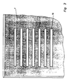
- Figs. 1 and 2 show examples of a cutting tool for punching holes or slits in a plaster plate 1.
- the tool comprises a patrix, the main part 4 of which holds the punches 7, 8 and moves them in and out of the matrix 2, when the pressing piece actuates the tool.
- a number of helical springs 6 which serve the purpose of ensuring the contact pressure on the plaster plate 1 in the working position. It is indeed important that the control plate is held to abut closely to the plaster plate in order thereby to ensure a pure and clean cut and at the same time serve the purpose of being tearing device in the tool.
- the matrix comprises an upper cutting plate 2 with holes 3 and with a base plate below where the punched out material 9 is expelled through the tapered holes, as shown in fig. 2.
- the punches 7, 8 are seen from the end. As will appear, the punches have different lengths in that every other punch 8 has a length exceeding the lenght of the other punches 7 by a distance being at least larger than the thickness of the plaster plate 1. Only every other punch 8 is pressed down to form the slits 5, and the patrix may then be pressed further down in order to punch interjacent slits by means of the shorther punches 7.
- each punch 7, 8 is supplied with an inclined blade 10, which may form an angle ⁇ to the horizontal, i.e. in relation to the matrix, of approx. 13°.
- This inclination has in practice proved to provide the best cut.
- the punching takes place, it starts in the protruding part of the blade 10 and runs evenly from there until the slit 15 has been formed. Since the cutting progresses evenly in the same direction, the punched out material 9 will be led away in an even flow, and there is no risk of blocking.
- Fig. 1 is a cross section of the blade 10. This comprises a double-blade 11 running along the two side edges of the punch and is formed by a groove 12 running in the centre of the punch.
- a blade 11 which cuts the outer part of the slit first and thus ensures a completely pure and clean cut.
- the punch will be evenly loaded during the punching. In order to even out the loads even more, every other punch may be turned so as to be turned at an angle of 180° in relation to the adjacent punch.
- a whole plate 1 is placed in the tool with the patrixes lifted.
- the tool may be actuated to punch the first set of slits.
- the interjacent slits are punched, and when this punching is completed, the patrix is lifted and the plate may ne shifted to the next punching position. This process is repeated until the whole plate is punched and ready for use as an acoustic plate.
Landscapes
- Engineering & Computer Science (AREA)
- Mechanical Engineering (AREA)
- Life Sciences & Earth Sciences (AREA)
- Forests & Forestry (AREA)
- Mining & Mineral Resources (AREA)
- Perforating, Stamping-Out Or Severing By Means Other Than Cutting (AREA)
- Polishing Bodies And Polishing Tools (AREA)
- Paper (AREA)
- Glass Compositions (AREA)
- Medicinal Preparation (AREA)
- Radiation-Therapy Devices (AREA)
Claims (4)
Priority Applications (1)
| Application Number | Priority Date | Filing Date | Title |
|---|---|---|---|
| AT86904115T ATE66177T1 (de) | 1985-07-01 | 1986-06-26 | Verfahren und werkzeug zum lochstanzen von gipsplatten. |
Applications Claiming Priority (2)
| Application Number | Priority Date | Filing Date | Title |
|---|---|---|---|
| DK298985A DK152266B (da) | 1985-07-01 | 1985-07-01 | Fremgangsmaade og vaerktoej til hulning af gipsplader |
| DK2989/85 | 1985-07-01 |
Publications (2)
| Publication Number | Publication Date |
|---|---|
| EP0227760A1 EP0227760A1 (de) | 1987-07-08 |
| EP0227760B1 true EP0227760B1 (de) | 1991-08-14 |
Family
ID=8117901
Family Applications (1)
| Application Number | Title | Priority Date | Filing Date |
|---|---|---|---|
| EP86904115A Expired - Lifetime EP0227760B1 (de) | 1985-07-01 | 1986-06-26 | Verfahren und werkzeug zum lochstanzen von gipsplatten |
Country Status (10)
| Country | Link |
|---|---|
| US (1) | US4898056A (de) |
| EP (1) | EP0227760B1 (de) |
| AT (1) | ATE66177T1 (de) |
| AU (1) | AU6133786A (de) |
| DE (1) | DE3680890D1 (de) |
| DK (1) | DK152266B (de) |
| ES (1) | ES2001162A6 (de) |
| FI (1) | FI870680A0 (de) |
| NO (1) | NO161964C (de) |
| WO (1) | WO1987000116A1 (de) |
Families Citing this family (24)
| Publication number | Priority date | Publication date | Assignee | Title |
|---|---|---|---|---|
| US5709138A (en) * | 1994-01-03 | 1998-01-20 | Martin Marietta Corporation | Method and apparatus for precision cutting of fibers |
| US6880441B1 (en) | 1996-06-06 | 2005-04-19 | International Business Machines Corporation | Precision punch and die design and construction |
| GB9707372D0 (en) * | 1997-04-11 | 1997-05-28 | Bpb Plc | Cementitiuos tile |
| GB2353489B (en) * | 1997-04-11 | 2001-10-10 | Bpb Plc | Cementitious tile |
| JP3722258B2 (ja) * | 1998-09-25 | 2005-11-30 | 日本碍子株式会社 | 打抜き加工用パンチ装置、打抜き加工用パンチおよび打抜き加工用パンチの製造方法 |
| IT1311786B1 (it) * | 1999-05-05 | 2002-03-19 | Ger Elettronica S R L | Macchina per marcare mediante perforazione pelli od altri articoli infoglio. |
| JP2001062784A (ja) * | 1999-08-27 | 2001-03-13 | Ngk Insulators Ltd | 脆性材料の穿孔方法及びそれに用いる穿孔用金型 |
| JP4767385B2 (ja) * | 2000-01-19 | 2011-09-07 | 大同工業株式会社 | 孔明け装置 |
| US7032812B2 (en) * | 2000-05-11 | 2006-04-25 | Euromac S.P.A. | Quick-extraction punch-holder adapter for converting punching machines from a single-punch to a multiple-punch configuration |
| JP2002028737A (ja) * | 2000-07-07 | 2002-01-29 | Fujitsu Ltd | プレス打ち抜き加工方法及びプレス打ち抜き加工装置 |
| US6464121B2 (en) * | 2000-12-21 | 2002-10-15 | Xerox Corporation | Specialized tool adapted for a process for manufacture and interconnection between adjoining printed wiring boards |
| EP1234922A1 (de) * | 2001-02-19 | 2002-08-28 | Mäder AG Innenausbau | Verfahren und Vorrichtung zum Herstellen eines plattenförmigen schallabsorbierenden Elementes |
| JP3641594B2 (ja) * | 2001-03-30 | 2005-04-20 | Uht株式会社 | 多軸穿孔装置 |
| TW559576B (en) * | 2002-03-20 | 2003-11-01 | Hon Hai Prec Ind Co Ltd | Electric-control progressing tool |
| WO2004035274A1 (ja) * | 2002-10-21 | 2004-04-29 | Daido Kogyo Co.,Ltd. | 孔明け装置 |
| CN100335248C (zh) * | 2003-11-05 | 2007-09-05 | 致伸科技股份有限公司 | 应用于打孔装置中的刀刃构造 |
| US20060042435A1 (en) * | 2004-08-30 | 2006-03-02 | Seiko Epson Corporation | Working method for forming minute holes, tool used in the method, method and apparatus for manufacturing liquid ejecting head |
| JP4517778B2 (ja) * | 2004-08-30 | 2010-08-04 | セイコーエプソン株式会社 | 微細穴の穿設加工方法、及び液体噴射ヘッドの製造装置 |
| US20070044618A1 (en) * | 2005-08-30 | 2007-03-01 | Marks Joel S | Hole punch element |
| US20070044624A1 (en) * | 2005-08-30 | 2007-03-01 | Marks Joel S | Hole punch element |
| JP5794220B2 (ja) * | 2012-12-14 | 2015-10-14 | 株式会社村田製作所 | キャリアテープ製造用金型およびキャリアテープの製造方法 |
| DE102014214547A1 (de) | 2014-07-24 | 2016-01-28 | Sennheiser Electronic Gmbh & Co. Kg | Verfahren zum Herstellen von akustischen Widerständen |
| JP6568443B2 (ja) * | 2015-09-30 | 2019-08-28 | 日本特殊陶業株式会社 | セラミック積層体の製造方法及び切断装置 |
| GB202011887D0 (en) * | 2020-07-30 | 2020-09-16 | British American Tobacco Investments Ltd | Method and apparatus for manufacturing a consumable unit for an inhalation device |
Family Cites Families (25)
| Publication number | Priority date | Publication date | Assignee | Title |
|---|---|---|---|---|
| CA589679A (en) * | 1959-12-29 | Plastic Binding Corporation | Gang punch | |
| US858066A (en) * | 1905-12-22 | 1907-06-25 | William Fehr | Punching-machine. |
| US907877A (en) * | 1908-02-12 | 1908-12-29 | Louisa M Rader | Machine for plaster-boards. |
| FR592179A (fr) * | 1924-03-22 | 1925-07-28 | Perfectionnement aux outils et poinçons à main pour le perçage et l'estampage | |
| US2182744A (en) * | 1938-08-08 | 1939-12-05 | J B Ehrsam & Sons Mfg Company | Punch |
| US2408488A (en) * | 1939-06-08 | 1946-10-01 | Celotex Corp | Method of perforating gypsum lath |
| US2325490A (en) * | 1942-01-09 | 1943-07-27 | Herbert O Elftman | Pressure indicating method and apparatus |
| US2622682A (en) * | 1946-05-31 | 1952-12-23 | John F Kopczynski | Punching die |
| US2633441A (en) * | 1950-08-07 | 1953-03-31 | George A Buttress | Method of making perforated composition plasterboard |
| US2808108A (en) * | 1956-03-09 | 1957-10-01 | Samuel C Pellegrino | Adjustable perforating punch assembly |
| US3248977A (en) * | 1959-02-24 | 1966-05-03 | Armstrong Cork Co | Method for punching acoustical tile |
| US3143026A (en) * | 1962-10-01 | 1964-08-04 | Wood Conversion Co | Tool for punching acoustic holes |
| US3130885A (en) * | 1962-11-01 | 1964-04-28 | Fleming John Stuart | Punch and die for tearing paper |
| US3334809A (en) * | 1964-07-13 | 1967-08-08 | Vyzk Ustav Matemat Stroju | High-speed operated apparatus for punching recording tape |
| US3461754A (en) * | 1966-12-07 | 1969-08-19 | Armstrong Cork Co | Rotary drum for fissuring acoustical material |
| DE1679924B2 (de) * | 1967-04-07 | 1974-02-21 | G. Bauknecht Gmbh, Elektrotechnische Fabriken, 7000 Stuttgart | Werkzeug zum Herstellen polygonaler, sich konisch verjüngender Durchbrüche in einer mit einer Kunststoff-Folie kaschierten Hartschaumplatte aus Kunststoff |
| US3504588A (en) * | 1967-11-29 | 1970-04-07 | Gen Binding Corp | Punching configuration |
| US3538797A (en) * | 1968-11-22 | 1970-11-10 | Conwed Corp | Apparatus for punching acoustical board |
| US3656394A (en) * | 1970-08-10 | 1972-04-18 | Tally Corp | Punch configuration |
| SU442049A1 (ru) * | 1971-12-20 | 1974-09-05 | Каунасский Политехнический Институт | Пуансон дл пробивки отверстий в листовом материале |
| US3774425A (en) * | 1971-12-23 | 1973-11-27 | J Veneziano | Portable shaping tool |
| CS194052B1 (en) * | 1977-09-01 | 1979-11-30 | Vladimir Muzik | Device for depreciation of the bank-notes |
| DE2758697A1 (de) * | 1977-12-29 | 1979-07-05 | Gail Ag | Verfahren und hilfswerkzeug zur herstellung von durchbruechen in keramischen platten |
| US4228709A (en) * | 1979-06-04 | 1980-10-21 | Panduit Corp. | Flat cable preparation tool assembly |
| SE427906B (sv) * | 1979-06-08 | 1983-05-24 | Westin & Backlund Ab | Sett att utforma klipp- och/eller gradpressverktyg med utbytbara skereggar |
-
1985
- 1985-07-01 DK DK298985A patent/DK152266B/da not_active Application Discontinuation
-
1986
- 1986-06-26 AT AT86904115T patent/ATE66177T1/de not_active IP Right Cessation
- 1986-06-26 DE DE8686904115T patent/DE3680890D1/de not_active Expired - Lifetime
- 1986-06-26 AU AU61337/86A patent/AU6133786A/en not_active Abandoned
- 1986-06-26 EP EP86904115A patent/EP0227760B1/de not_active Expired - Lifetime
- 1986-06-26 WO PCT/DK1986/000077 patent/WO1987000116A1/en not_active Ceased
- 1986-07-01 ES ES8600072A patent/ES2001162A6/es not_active Expired
-
1987
- 1987-02-12 NO NO870549A patent/NO161964C/no unknown
- 1987-02-18 FI FI870680A patent/FI870680A0/fi not_active Application Discontinuation
-
1988
- 1988-07-29 US US07/228,809 patent/US4898056A/en not_active Expired - Fee Related
Also Published As
| Publication number | Publication date |
|---|---|
| FI870680A7 (fi) | 1987-02-18 |
| DE3680890D1 (de) | 1991-09-19 |
| NO870549D0 (no) | 1987-02-12 |
| NO161964B (no) | 1989-07-10 |
| ATE66177T1 (de) | 1991-08-15 |
| ES2001162A6 (es) | 1988-05-01 |
| NO870549L (no) | 1987-02-12 |
| EP0227760A1 (de) | 1987-07-08 |
| AU6133786A (en) | 1987-01-30 |
| FI870680A0 (fi) | 1987-02-18 |
| DK152266B (da) | 1988-02-15 |
| WO1987000116A1 (en) | 1987-01-15 |
| DK298985D0 (da) | 1985-07-01 |
| DK298985A (da) | 1987-01-02 |
| NO161964C (no) | 1989-10-18 |
| US4898056A (en) | 1990-02-06 |
Similar Documents
| Publication | Publication Date | Title |
|---|---|---|
| US4898056A (en) | Method and tool for punching plaster plates | |
| US5722386A (en) | Method and apparatus for forming ornamental edges on cement siding | |
| US4969380A (en) | Gypsum board grooving system | |
| CA2386123C (en) | Improvements to ceramic cutters | |
| KR0183404B1 (ko) | 개량된 마모성 스크린 플레이트 및 그 제조방법 | |
| ES2041022T3 (es) | Dispositivo de corte y de punzonado para materias en hojas. | |
| DK0669861T3 (da) | Savklinge og en fremgangsmåde og en anordning til fremstilling af en savklinge, idet værktøjet eller emnet anbringes i vinkel mellem hver indskæring | |
| JP2003211391A (ja) | 回転ダイ打抜き装置および回転ダイからスクラップ材を除去する方法 | |
| IT8367926A0 (it) | Procedimento ed apparecchio per regolare la profondita di taglio nel la direzione radiale di un utensile di taglio rotativo in una macchina utensile | |
| US20040040425A1 (en) | Method and apparatus for cutting sheet metal | |
| SU1692304A3 (ru) | Деревообрабатывающий станок Черкасова | |
| JPS61193801A (ja) | 多軸モルダ−による木材の縦挽き方法 | |
| JPH04217498A (ja) | 孔明け工具 | |
| KR930000931Y1 (ko) | 톱밥 제조기 | |
| CN105291197A (zh) | 一种分解冲击应力的切割装置 | |
| JPH07266302A (ja) | 木質板材の加工用工具 | |
| CA1061706A (en) | Compound angle cutting edge and method of using same | |
| JPS6021201Y2 (ja) | 木材加工装置 | |
| ATE352403T1 (de) | Verfahren zur planbearbeitung von rundholz | |
| CA1062604A (en) | Compound angle cutting edge and method of using same | |
| EP1192027A4 (de) | Verfahren und vorrichtung zum profilieren von baumstämen | |
| JPH08257991A (ja) | プリント配線板の切断方法 | |
| JP2000219525A (ja) | 異形孔明方法および装置 | |
| CN105269627A (zh) | 多功能工件切割装置 | |
| JPS5817003B2 (ja) | 凹凸様石膏ボ−ド化粧面の加工装置 |
Legal Events
| Date | Code | Title | Description |
|---|---|---|---|
| PUAI | Public reference made under article 153(3) epc to a published international application that has entered the european phase |
Free format text: ORIGINAL CODE: 0009012 |
|
| 17P | Request for examination filed |
Effective date: 19870214 |
|
| AK | Designated contracting states |
Kind code of ref document: A1 Designated state(s): AT BE CH DE FR GB IT LI LU NL SE |
|
| 17Q | First examination report despatched |
Effective date: 19881025 |
|
| GRAA | (expected) grant |
Free format text: ORIGINAL CODE: 0009210 |
|
| AK | Designated contracting states |
Kind code of ref document: B1 Designated state(s): AT BE CH DE FR GB IT LI LU NL SE |
|
| REF | Corresponds to: |
Ref document number: 66177 Country of ref document: AT Date of ref document: 19910815 Kind code of ref document: T |
|
| REF | Corresponds to: |
Ref document number: 3680890 Country of ref document: DE Date of ref document: 19910919 |
|
| ET | Fr: translation filed | ||
| ITF | It: translation for a ep patent filed | ||
| PLBI | Opposition filed |
Free format text: ORIGINAL CODE: 0009260 |
|
| 26 | Opposition filed |
Opponent name: DANOGIPS A/S Effective date: 19920514 |
|
| NLR1 | Nl: opposition has been filed with the epo |
Opponent name: DANOGIPS A/S |
|
| PLBN | Opposition rejected |
Free format text: ORIGINAL CODE: 0009273 |
|
| STAA | Information on the status of an ep patent application or granted ep patent |
Free format text: STATUS: OPPOSITION REJECTED |
|
| EPTA | Lu: last paid annual fee | ||
| 27O | Opposition rejected |
Effective date: 19940319 |
|
| NLR2 | Nl: decision of opposition | ||
| EAL | Se: european patent in force in sweden |
Ref document number: 86904115.2 |
|
| PGFP | Annual fee paid to national office [announced via postgrant information from national office to epo] |
Ref country code: LU Payment date: 19950601 Year of fee payment: 10 |
|
| PGFP | Annual fee paid to national office [announced via postgrant information from national office to epo] |
Ref country code: GB Payment date: 19950615 Year of fee payment: 10 |
|
| PGFP | Annual fee paid to national office [announced via postgrant information from national office to epo] |
Ref country code: SE Payment date: 19950622 Year of fee payment: 10 |
|
| PGFP | Annual fee paid to national office [announced via postgrant information from national office to epo] |
Ref country code: NL Payment date: 19950627 Year of fee payment: 10 |
|
| PGFP | Annual fee paid to national office [announced via postgrant information from national office to epo] |
Ref country code: AT Payment date: 19950628 Year of fee payment: 10 |
|
| PGFP | Annual fee paid to national office [announced via postgrant information from national office to epo] |
Ref country code: BE Payment date: 19950710 Year of fee payment: 10 |
|
| PGFP | Annual fee paid to national office [announced via postgrant information from national office to epo] |
Ref country code: CH Payment date: 19950925 Year of fee payment: 10 |
|
| PG25 | Lapsed in a contracting state [announced via postgrant information from national office to epo] |
Ref country code: LU Free format text: LAPSE BECAUSE OF NON-PAYMENT OF DUE FEES Effective date: 19960626 Ref country code: GB Effective date: 19960626 Ref country code: AT Effective date: 19960626 |
|
| PG25 | Lapsed in a contracting state [announced via postgrant information from national office to epo] |
Ref country code: SE Effective date: 19960627 |
|
| PG25 | Lapsed in a contracting state [announced via postgrant information from national office to epo] |
Ref country code: LI Effective date: 19960630 Ref country code: CH Effective date: 19960630 Ref country code: BE Effective date: 19960630 |
|
| BERE | Be: lapsed |
Owner name: GYPROC A/S Effective date: 19960630 |
|
| PG25 | Lapsed in a contracting state [announced via postgrant information from national office to epo] |
Ref country code: NL Effective date: 19970101 |
|
| GBPC | Gb: european patent ceased through non-payment of renewal fee |
Effective date: 19960626 |
|
| REG | Reference to a national code |
Ref country code: CH Ref legal event code: PL |
|
| EUG | Se: european patent has lapsed |
Ref document number: 86904115.2 |
|
| NLV4 | Nl: lapsed or anulled due to non-payment of the annual fee |
Effective date: 19970101 |
|
| PGFP | Annual fee paid to national office [announced via postgrant information from national office to epo] |
Ref country code: FR Payment date: 20010627 Year of fee payment: 16 |
|
| PGFP | Annual fee paid to national office [announced via postgrant information from national office to epo] |
Ref country code: DE Payment date: 20010726 Year of fee payment: 16 |
|
| PG25 | Lapsed in a contracting state [announced via postgrant information from national office to epo] |
Ref country code: DE Free format text: LAPSE BECAUSE OF NON-PAYMENT OF DUE FEES Effective date: 20030101 |
|
| PG25 | Lapsed in a contracting state [announced via postgrant information from national office to epo] |
Ref country code: FR Free format text: LAPSE BECAUSE OF NON-PAYMENT OF DUE FEES Effective date: 20030228 |
|
| REG | Reference to a national code |
Ref country code: FR Ref legal event code: ST |
|
| PG25 | Lapsed in a contracting state [announced via postgrant information from national office to epo] |
Ref country code: IT Free format text: LAPSE BECAUSE OF NON-PAYMENT OF DUE FEES;WARNING: LAPSES OF ITALIAN PATENTS WITH EFFECTIVE DATE BEFORE 2007 MAY HAVE OCCURRED AT ANY TIME BEFORE 2007. THE CORRECT EFFECTIVE DATE MAY BE DIFFERENT FROM THE ONE RECORDED. Effective date: 20050626 |