EP0227906B1 - Elektronisches Saitenmusikinstrument - Google Patents
Elektronisches Saitenmusikinstrument Download PDFInfo
- Publication number
- EP0227906B1 EP0227906B1 EP86114768A EP86114768A EP0227906B1 EP 0227906 B1 EP0227906 B1 EP 0227906B1 EP 86114768 A EP86114768 A EP 86114768A EP 86114768 A EP86114768 A EP 86114768A EP 0227906 B1 EP0227906 B1 EP 0227906B1
- Authority
- EP
- European Patent Office
- Prior art keywords
- string
- vibration
- signal
- fret
- stringed instrument
- Prior art date
- Legal status (The legal status is an assumption and is not a legal conclusion. Google has not performed a legal analysis and makes no representation as to the accuracy of the status listed.)
- Expired - Lifetime
Links
- 238000013016 damping Methods 0.000 claims description 14
- 238000001514 detection method Methods 0.000 claims description 10
- 239000002184 metal Substances 0.000 claims description 8
- 230000000644 propagated effect Effects 0.000 claims description 3
- 239000011295 pitch Substances 0.000 description 31
- 238000002592 echocardiography Methods 0.000 description 14
- 230000001902 propagating effect Effects 0.000 description 7
- 238000010586 diagram Methods 0.000 description 6
- 230000002238 attenuated effect Effects 0.000 description 4
- 238000006243 chemical reaction Methods 0.000 description 4
- 230000004048 modification Effects 0.000 description 4
- 238000012986 modification Methods 0.000 description 4
- 239000000919 ceramic Substances 0.000 description 3
- 238000010276 construction Methods 0.000 description 3
- 230000000994 depressogenic effect Effects 0.000 description 3
- 239000003990 capacitor Substances 0.000 description 2
- 238000007796 conventional method Methods 0.000 description 2
- 230000003111 delayed effect Effects 0.000 description 2
- 238000004519 manufacturing process Methods 0.000 description 2
- 229910000831 Steel Inorganic materials 0.000 description 1
- 230000002411 adverse Effects 0.000 description 1
- 230000005540 biological transmission Effects 0.000 description 1
- 230000007423 decrease Effects 0.000 description 1
- 239000000284 extract Substances 0.000 description 1
- 239000000463 material Substances 0.000 description 1
- 238000000034 method Methods 0.000 description 1
- 230000002441 reversible effect Effects 0.000 description 1
- 239000007787 solid Substances 0.000 description 1
- 239000010959 steel Substances 0.000 description 1
Images





Classifications
-
- G—PHYSICS
- G10—MUSICAL INSTRUMENTS; ACOUSTICS
- G10H—ELECTROPHONIC MUSICAL INSTRUMENTS; INSTRUMENTS IN WHICH THE TONES ARE GENERATED BY ELECTROMECHANICAL MEANS OR ELECTRONIC GENERATORS, OR IN WHICH THE TONES ARE SYNTHESISED FROM A DATA STORE
- G10H3/00—Instruments in which the tones are generated by electromechanical means
- G10H3/12—Instruments in which the tones are generated by electromechanical means using mechanical resonant generators, e.g. strings or percussive instruments, the tones of which are picked up by electromechanical transducers, the electrical signals being further manipulated or amplified and subsequently converted to sound by a loudspeaker or equivalent instrument
- G10H3/14—Instruments in which the tones are generated by electromechanical means using mechanical resonant generators, e.g. strings or percussive instruments, the tones of which are picked up by electromechanical transducers, the electrical signals being further manipulated or amplified and subsequently converted to sound by a loudspeaker or equivalent instrument using mechanically actuated vibrators with pick-up means
- G10H3/18—Instruments in which the tones are generated by electromechanical means using mechanical resonant generators, e.g. strings or percussive instruments, the tones of which are picked up by electromechanical transducers, the electrical signals being further manipulated or amplified and subsequently converted to sound by a loudspeaker or equivalent instrument using mechanically actuated vibrators with pick-up means using a string, e.g. electric guitar
-
- G—PHYSICS
- G10—MUSICAL INSTRUMENTS; ACOUSTICS
- G10H—ELECTROPHONIC MUSICAL INSTRUMENTS; INSTRUMENTS IN WHICH THE TONES ARE GENERATED BY ELECTROMECHANICAL MEANS OR ELECTRONIC GENERATORS, OR IN WHICH THE TONES ARE SYNTHESISED FROM A DATA STORE
- G10H2220/00—Input/output interfacing specifically adapted for electrophonic musical tools or instruments
- G10H2220/155—User input interfaces for electrophonic musical instruments
- G10H2220/165—User input interfaces for electrophonic musical instruments for string input, i.e. special characteristics in string composition or use for sensing purposes, e.g. causing the string to become its own sensor
- G10H2220/181—User input interfaces for electrophonic musical instruments for string input, i.e. special characteristics in string composition or use for sensing purposes, e.g. causing the string to become its own sensor by nonresonant wave interaction, i.e. string sensing using wavelengths unrelated to string resonant wavelengths, e.g. ultrasonic waves, microwave or light waves, propagated along a musical instrument string to measure its fret length, e.g. for MIDI transcription
-
- Y—GENERAL TAGGING OF NEW TECHNOLOGICAL DEVELOPMENTS; GENERAL TAGGING OF CROSS-SECTIONAL TECHNOLOGIES SPANNING OVER SEVERAL SECTIONS OF THE IPC; TECHNICAL SUBJECTS COVERED BY FORMER USPC CROSS-REFERENCE ART COLLECTIONS [XRACs] AND DIGESTS
- Y10—TECHNICAL SUBJECTS COVERED BY FORMER USPC
- Y10S—TECHNICAL SUBJECTS COVERED BY FORMER USPC CROSS-REFERENCE ART COLLECTIONS [XRACs] AND DIGESTS
- Y10S84/00—Music
- Y10S84/30—Fret control
Definitions
- the present invention relates to an electronic stringed instrument.
- a conventional method of detecting a fret position in the process for producing musical tones in such an electronic stringed instrument is disclosed in US-A-4 151 775 and will be described with reference to Fig. 1.
- a player depresses a string 1 with his finger at a desired position on a fingerboard so as to generate a specific musical tone
- the string 1 is brought into contact with the specific fret and the length of the string 1 to be picked is determined.
- the fret position is not discriminated.
- the fret position is discriminated after the player picks the string 1. More specifically, when the string 1 is picked, the string 1 vibrates in a period corresponding to the string length.
- the vibrations of the string 1 are converted by an electromagnetic pickup 2 into an electrical signal having a waveshape similar to the vibrations of the string 1.
- This electrical signal is waveshaped by a low-pass filter 3.
- a peak detector 4 detects the peak in amplitude of the waveshaped signal.
- a pulse converter 5 generates pulses in synchronism with the detection result of the peak detector 4.
- a pulse interval measuring circuit 6 measures an interval of pulses generated in synchronism with peak detection.
- the pulse interval measuring circuit 6 generates a digital signal corresponding to the pulse interval.
- a value represented by this digital signal corresponds to the fundamental frequency of the string 1 and also represents the position of the fret which which the string 1 is in contact.
- a tone generator 7 generates a musical tone signal on the basis of this digital signal.
- a sound system 8 produces a musical tone represented by the musical tone signal.
- the position of the fret with which the string 1 is in contact is detected on the basis of the period of vibration of the picked string 1. At least a period corresponding to a possible maximum vibration period of the string 1 must be preset for detecting the peak. For example, a period of about 1/80 second is required for a typical six-string guitar.
- the vibrations of the string 1 immediately after picking have a large harmonic overtone component ratio, and this ratio causes variations in peak. Therefore, the initial peak is not used for discriminating the fret position, and the fret position is detected according to the second or subsequent peak at which the harmonic overtone component ratio is rapidly reduced. In the conventional arrangement, it takes a relatively long period of time until a musical tone is produced by the sound system after the player picks the string 1. The player experiences an unnatural feeling.
- each electromagnetic pickup 2 is adversely affected by not only the string 1 assigned thereto but also by adjacent strings. The fret position may therefore be erroneously discriminated.
- an object of the present invention to provide an electronic stringed instrument for accurately detecting a position of a fret with which a string depressed by a player's finger is in contact.
- an electronic stringed instrument comprising: an instrument body; a string which is stretched above the instrument body; a plurality of metal frets which are provided on the instrument body and below the string so that a player's depression of the string causes contact between the string and one or ones of the plurality of metal frets; ultrasonic transmitting/receiving means, provided on the instrument body and coupled to a specific point of the string, for generating an ultrasonic wave so that the ultrasonic wave is propagated through the string toward the nearest fret to the specific point among the fret or frets contacting the string and for receiving an echo wave which is a reflected wave of the ultrasonic wave from the nearest fret; and fret discriminating means connected to the ultrasonic transmitting/receiving means for discriminating the nearest fret among the plurality of metal frets according to a time difference between generation of the ultrasonic wave and the receipt of the echo wave and for generating a fret signal representing the nearest fret.
- the present invention is based on an assumption that a propagation time of an ultrasonic wave to be propagated through a string is proportional to a string length.
- An ultrasonic transmitting/receiving means intermittently transmits an ultrasonic wave.
- the ultrasonic wave propagates from one end to the other end of the string.
- the string is brought into contact with at least one of the plurality of frets so that a string length is defined by this fret.
- the ultrasonic wave propagating from one end to the other end of the string is reflected by the fret with which the string is in contact, and an echo is generated.
- the echo propagates from the fret to one end of the string and is received by the ultrasonic transmitting/receiving means.
- the fret discriminating means discriminates the fret position according to the ultrasonic wave intermittently transmitted from the ultrasonic transmitting/receiving means and the echo received thereto. Therefore, the time required for discriminating the fret is the ultrasonic propagation time for which the ultrasonic wave reciprocates between one end of the string and the fret with which this string is contact.
- the fret discrimination time is not associated with the string diameter.
- the speed of the ultrasonic wave propagating through a solid object is very high. The player normally depresses the string before picking it. Therefore, the musical tone can be produced substantially simultaneously with picking of the string, and the musical tone upon picking can be obtained in a short response time.
- the ultrasonic wave propagates through the medium, unlike in the case of a magnetic field.
- the ultrasonic wave is attenuated upon propagation through the medium. Even if another ultrasonic source is located near the ultrasonic transmitting/receiving means, it is substantially free from the influence of an ultrasonic source nearby. Therefore, the fret discriminating means can accurately discriminate the fret position according to only the ultrasonic wave transmitted thereby and the echo derived from the transmitted ultrasonic wave.
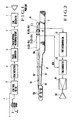
- Fig. 2 shows an embodiment wherein the present invention is applied to a six-string guitar.
- reference numeral 11 denotes a guitar body.
- metal frets 13 1 , 13 2 ,.., 13 n are fixed on a fingerboard 13 in a direction perpendicular to the longitudinal direction of the fingerboard 13, and the fingerboard 13 is fixed on a neck 12 connected to the body 11.
- Bare steel strings 151, 152,... 156 having different diameters are kept taut between tuning keys 12a fixed at the head at the distal end of the neck 12 and a tailpiece 14 extending on the body 11.
- Six ceramic piezoelectric elements 161, 162,... 166 as the ultrasonic transmitting/receiving means are separated from each other and mounted near the tailpiece 14.
- the strings 151 to 156 are respectively in contact with the piezoelectric elements 161 to 166.
- a pair of bolts 18A extend on the body 11 so as to cause a bridge holder 17 to be vertically movable.
- the bridge holder 17 is urged by the elastic forces of the strings 151 to 156 against nuts 18 threadably engaged with the pair of bolts 18A.
- the nuts 18 are turned. Holes each having a rectangular cross section are vertically formed from the upper surface of the bridge holder 17 and are spaced apart from each other at a predetermined pitch. Adjusting screws 191, 192,... 196 extend parallel to the strings 151, 152,... 156 through the holes.
- the heads of the adjusting screws 191 to 196 project from one side surface of the bridge holder 17 such that the screws 191 to 196 can be turned with a screwdriver.
- Bridges 201, 202,... 206 carrying the piezoelectric elements 161 to 166 are threadably engaged with the adjusting screws 191 to 196 extending through the holes formed in the bridge holder 17.
- the bridges 201 to 206 are moved parallel to the strings 151 to 156, respectively.
- the pivotal movement of the bridges 201 to 206 is defined by the edges of the holes in a direction parallel to the strings.
- the bridges 201 to 206 can be moved within the above-mentioned range in the axial direction of the adjusting screws 191 to 196, i.e., the extending direction of the strings 151 to 156.
- a common damper 23 is arranged between the tailpiece 14 and the bridges 201 to 206.
- the damper 23 is made of rubber for absorbing vibrations of the strings.
- Electromagnetic pickups 211, 212,... 216 are arranged between the piezoelectric elements 161, 162,... 166 and the frets 131, 132,... 13 n fixed on the fingerboard 13 of the neck 12 so as to respectively correspond to the strings 151, 152,... 156 (i.e., independently).
- the electromagnetic pickups 211, 212,... 216 detect vibrations of the corresponding strings 151, 152,... 156 picked by the player. As a result of the detection, each electromagnetic pickup supplies a picking signal KON to a tone generator 47.
- the piezoelectric elements 161 to 166 are connected to a fret discriminating means 22.
- a rubber damper 24 is arranged at the end of the fingerboard 13 near each key 12a to absorb the string vibrations when the string is not held on the fret.
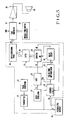
- the electrical circuit connected to the piezoelectric elements 161 to 166 and the electromagnetic pickups 211 to 216 will be described with reference to Figs. 5 to 7.
- the electrical circuit in Figs. 5 to 7 is arranged for each one of the strings 151 to 156. In the following description, one (associated with the string 151) of the electrical circuits will be exemplified.
- Predetermined RF pulses (or pulses including the RF wave) P1 are generated by a pulse generator 31 at an interval of 3 to 10 msec.
- the RF pulses are applied from a transmitter 32 to the piezoelectric element 161 (time t1 in Fig. 6A).
- the piezoelectric element 161 generates an ultrasonic wave having a frequency of 400 kHz to 1 MHz (in the case of bare wires).
- the ultrasonic wave propagates through the string 151.
- the string is brought into contact with at least one of the frets 131 to 13 n according to the depression position of the string 151.
- the ultrasonic wave is reflected by one of the metal frets 131 to 13 n which is in contact with the string 151, so that an echo is generated.
- a drive pulse generator 34 in a receiver 33 in Fig. 7 supplies a set signal S1 to a set terminal S of an RS flip-flop 35 (Fig. 6B).
- the RS flip-flop 35 supplies a gate enable signal S2 to a gate 36 (Fig. 6C) to open the gate 36.
- An output from a clock generator 37 for generating a clock signal C1 (Fig. 6D) is supplied as an output (Fig. 6E) of the gate 36 to a counter 38 while the gate enable signal S2 is supplied to the gate 36 (Fig. 6E).
- the counter 38 counts pulses of the clock signal C1 supplied from the clock generator 37.
- the piezoelectric element 161 When the echo reaches the piezoelectric element 161 at time t2, the piezoelectric element 161 generates an electrical signal S3 (Fig. 6F) having a waveform similar to that of the echo.
- the electrical signal S3 is then supplied to the receiver 33.
- an amplifier 39 in Fig. 7 amplifies the electrical signal S3.
- a high-pass filter (HPF) 40 eliminates a low-frequency component caused by string vibrations from the electrical signal S3.
- a pulse signal P2 (Fig. 6G) which goes high during the ON duration of the echo in response to the electrical signal S3 is output from a signal detector 41.
- the signal P2 is supplied to a reset terminal R of the RS flip-flop 35 through an OR gate 42.
- the gate enable signal S2 supplied from the RF flip-flop 35 goes low (Fig. 6C).
- the gate 36 is disabled and the counter 38 stops counting the clock pulses. Therefore, the counter 38 stores the number of clock pulses output between time t1 and time t2 (Fig. 6E).
- a falling edge differentiator 43 generates a pulse signal P3 (Fig. 6H) which rises at the trailing edge of the gate enable signal S2.
- the count of the counter 38 is latched by a latch 44 in response to the pulse signal P3.
- the pulse signal P3 is also supplied to a delay circuit 45.
- a delayed pulse P4 from the delay circuit 45 is supplied to a reset terminal RS of the counter 38, so that the counter 38 is ready for the next counting cycle. If the player does not depress the string 151 at any position and then the echo is not generated, the counter 38 overflows.
- An overflow signal OF from the counter 38 is supplied to an OR gate 42 (Fig. 4) in the receiver 33 to reset the RS flip-flop 35.
- the count of the counter 38 which is transferred to the latch 44 is converted into a key code signal KC by a data conversion table 46.
- the tone generator 47 specifies a pitch of a musical tone to be produced, according to the key code signal KC.
- a musical tone signal is generated according to the instruction from a musical tone control switch circuit 48 and is supplied to a sound system including an amplifier 49 and a loudspeaker 50. The sound system produces the musical tone having a pitch corresponding to the discriminated fret position.
- the position of the fret with which one of the strings 151 to 156 is in contact is discriminated according to the propagation time of the ultrasonic wave through the corresponding one of the strings 151 to 156 regardless of the string vibrations upon picking.
- the position of the fret contacting one of the strings 151 to 156 is discriminated in an ultrasonic reciprocal propagation time between one of the piezoelectric elements 161 to 166 and one of the frets 131 to 13 n which contacts the depressed string.
- a musical tone having a pitch corresponding to the position of the fret contacting the string can be generated simultaneously when the player picks the string.
- the ultrasonic wave propagating through the strings 151 to 156 cannot be transferred to the piezoelectric elements 161 to 166 without being through the bridges 201 to 206, the adjusting screws 191 to 196, and the bridge holder 17, the ultrasonic wave is greatly attenuated.
- the piezoelectric elements 161 to 166 do not therefore receive the influence from the ultrasonic wave propagating through the adjacent strings 151 to 156.
- Pitch data in place of the key code signal KC may be stored in the data conversion table 46 and may be supplied to the tone generator 47.
- the dynamic range (e.g., 10 V) of the RF pulse P1 applied from the transmitter 32 to the piezoelectric element 161 greatly differs from that (e.g., 0.6 V) of the electrical signal S3 based on the echo generated upon reflection of the ultrasonic wave by the fret. Therefore, separate discriminators may be arranged in the transmitter 32 and the receiver 33, respectively. Alternatively, a signal discriminator 60 shown in Fig. 8 may be arranged. More specifically, since the RF pulse P1 supplied from the transmitter 32 has a wide dynamic range, the DC component of the pulse P1 is removed by a capacitor 61, and the pulse P1 then passes through a pair of parallel diodes 62 and 63 reverse-biased with each other.
- the resultant pulse is then applied to the piezoelectric element 161. Since the RF pulse P1 is also supplied through diodes 64 and 65, the pulse cannot be detected as the electrical signal S3 by the receiver 33.
- the electrical signal S3 generated by the piezoelectric element 161 has a narrow dynamic range and does not pass through the diodes 64 and 65.
- the DC component of the signal S3 is eliminated by a capacitor 66, and the resultant pulse is supplied to the receiver 33.
- the electrical signal S3 does not pass through the diodes 62 and 63, it cannot be applied to the transmitter 32. Threshold levels of the diodes 62, 63, 64, and 65 fall within the range between the dynamic ranges of the RF pulse P1 and the electrical signal S3.
- the pulse generator 31, the transmitter 32, the receiver 33, the gate 36, the clock generator 37, the counter 38, the falling edge differentiator 43, the latch 44, the delay circuit 45, and the data conversion table 46 are arranged for each one of the strings 151 to 156.
- the RF pulses P1 may be generated by a single pulse generator 31 and sequentially supplied to the piezoelectric elements 161 to 166, and the echoes from the strings 151 to 156 may be processed by a single receiver 33, a single gate, a single clock generator 37, a single counter 38, a single falling edge differentiator 43, a single latch 44, a single delay circuit 45, and a single data conversion table 46 in a time-divisional manner. If fret position detection is time-divisionally performed, the arrangement of the fret discriminating means can be simplified.
- the amplifier 39 recieving the electrical signal S3 from the piezoelectric element 161 may be connected in parallel with the high-pass filter 40 and a low-pass-filter (LPF) 61.
- a picking component may be extracted from the electrical signal S3 or separately from the signal S3.
- the picking component extracted by the low-pass filter 61 is supplied to the tone generator 47.
- the picking components are extracted from the electrical signals S3 from the piezoelectric elements 161 to 166 to obtain picking signals KON, thereby eliminating the electromagnetic pickups 211 to 216 and thus simplifying the construction.
- the picking timings are discriminated on the basis of the low-frequency vibrations detected by the electromagnetic pickups.
- the fret is discriminated according to the propagation time of the ultrasonic signal propagating in the string through the piezoelectric element.
- Two types of vibration detecting means i.e., the piezoelectric element and the electromagnetic pickup
- a single detecting means is provided for detecting the picking timing and discriminating the fret contacting the picked string, as shown in Figs. 10 to 12.
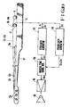
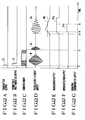
- FIG. 10 to 12G Another embodiment of the present invention will be described with reference to Figs. 10 to 12G.
- the same reference numerals as in Fig. 2 denote the same parts and functions in Fig. 10 to 12G.
- an instrument body 11, tuning keys 12a, a tailpiece 14, six strings 151 to 156 having different diameters and kept taut between the tuning keys 12a and the tailpiece 14, n frets 131 to 13 n fixed on a neck 12 of the body 1 in a direction substantially perpendicular to the strings 151 to 156, and a bridge holder 17 extending on the body 11 at the tailpiece 14 side and having ceramic piezoelectric elements 161 to 166 corresponding to the strings 151 to 156 are substantially the same as those of Fig. 2.
- the piezoelectric elements 161 to 166 are in direct contact with the strings 151 to 156, respectively.
- the piezoelectric elements 161 to 166 generate ultrasonic signals in response to drive pulses P1 as a first electric signal supplied from a pitch data generating means 137 and transmit the ultrasonic signals to the corresponding strings 151 to 156.
- the ultrasonic signals transmitted to the strings 151 to 156 propagate toward the frets 131 to 13 n through the strings 151 to 156.
- the ultrasonic signals are reflected by the frets contacting the corresponding strings, so that the corresponding echoes are generated.
- the echoes propagate back to the piezoelectric elements through the strings and are converted by the piezoelectric elements into reflection signals S11 as a second electrical signal.
- Each reflection signal S11 is supplied to the pitch data generating means 137.
- the pitch data generating means 137 counts the time interval between the sending timing of the drive pulse P1 and the reception timing of the reflection signal S11.
- the frets which caused generation of the echoes are discriminated according to the count results.
- the frets discriminated by the echoes represent pitches of the desired musical tones.
- the pitch data generating means 137 generates a pitch signal S12 representing the pitch of the tone to be produced.
- the pitch signal S12 is supplied to a musical tone signal generator 139.
- the picked strings are vibrated at low frequencies.
- the low-frequency vibrations are converted into low-frequency picking signals S13 as third electrical signals by the corresponding ones of the piezoelectric elements 161 to 166.
- Each picking signal S13 is detected by a picking data generating means 141.
- the picking data generating means 141 supplies a volume signal S14 representing a musical tone volume and a duration signal S15 representing the duration of the musical tone according to the picking signal S13 to the musical tone signal generator 139.
- the musical tone generator 139 generates a musical tone signal S16 according to the pitch signal S12, the volume signal S14, and the duration signal S15.
- the musical tone signal S16 is supplied to a sound system including an amplifier 49 and a loudspeaker 50, thereby producing a musical tone.
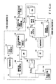
- Fig. 11 denotes a pulse generator for generating a drive pulse P1.
- the drive pulse P1 is supplied from the pulse generator 101 to the piezoelectric element 161 and a monostable multivibrator 105 through a transmitter 103 (Fig.
- the piezoelectric element 161 generates an ultrasonic wave in response to the drive pulse P1, and the ultrasonic wave is transmitted to the string 151 (N in Fig. 12D represents self-excited noise of the piezoelectric element 161).
- the ultrasonic wave transmitted to the string 151 propagates through the string 151 toward the frets 13 n ,... 131.
- the ultrasonic wave is reflected by one of the frets 131 to 13 n which is in contact with the string 151, and the corresponding echo is generated.
- the echo propagates back through the string 151 toward the piezoelectric element 161.
- the monostable multivibrator 105 generates a one-shot pulse P2 in response to the drive pulse P1.
- the one-shot pulse P2 is supplied to a pitch designation circuit 107 (Fig. 12B).
- the pitch designation circuit 107 causes its built-in counter 107a to count clock pulses in response to the one-shot pulse P2 (Fig. 12C).
- the piezoelectric element 151 When the echo reaches the piezoelectric element 151 at time t2, the piezoelectric element 151 generates the reflection signal S11 derived from the echo (Fig. 12D).
- the reflection signal S11 is amplified by an amplifier 109, and the amplified signal is supplied to a high-pass filter 111 and a low-pass filter 113.
- the reflection signal S11 Since the reflection signal S11 is generated on the basis of the echo of the ultrasonic signal, its frequency is very high. Therefore, the reflection signal S11 passes through only the high-pass filter 111, and the filtered signal is supplied to the pitch designation circuit 107.
- the counter 107a in the pitch designation circuit 107 stops counting the clock pulses, and the current count is held thereby (Fig. 12C). The count corresponds to a time interval between the sending timing of the drive pulse P1 and the reception timing of the reflection signal S11, thereby representing the fret which generated the echo.
- the pitch designation circuit 107 supplies the pitch signal S12 representing the pitch of the musical tone to the musical tone generator 139 according to the count.
- the string 151 When the player picks the string 151 to produce a desired musical tone after the pitch of the musical tone to be produced is determined, the string 151 is vibrated at a low frequency.
- the string vibrations are converted into the low-frequency picking signal S13 by the piezoelectric element 161 at time t3 (Fig. 12D).
- the picking signal S13 is amplified by an amplifier 109, and the amplified signal is filtered through only a low-pass filter 113.
- the filtered signal is then supplied to a waveshaper 115.
- the waveshaper 115 extracts an envelope of the picking signal S13 (Fig. 12E).
- a speed detector 117 in the next stage holds a peak value obtained after a lapse of a predetermined period of time.
- the volume signal S14 is formed according to the value (Fig. 12F). In general, if the string is strongly picked, the amplitude of the picked string is increased. The peak value obtained after the lapse of the predetermined period of time is proportional to the picking strength and to the volume level of the musical tone. An output from the waveshaper 115 is also supplied to a duration discriminator 119 so that the peak value is compared with a threshold value Vth. If the output from the waveshaper 115 exceeds the threshold value Vth at time t4, the duration signal S15 output from the duration discriminator 119 goes high. When the output from the waveshaper 115 is lower than the threshold value Vth at time t5, the duration signal S15 goes low (Fig. 12G).
- a switch circuit 121 While the duration signal S15 is kept high, a switch circuit 121 is turned on and then the volume signal S14 is supplied to a voltage-controlled amplifier (VCA) 123.
- VCA voltage-controlled amplifier
- the musical tone generator 139 receives the output from the amplifier 123 and the pitch signal S12 and generates a musical tone signal having predetermined pitch and volume levels. The musical tone signal is supplied to the sound system.
- the piezoelectric elements 161 to 166 can be used to generate the reflection signal S11 and the picking signal S13, thereby simplifying the overall construction and reducing the manufacturing cost.
- the volume signal S14 and the duration signal S15 are generated by the picking data generating means 141.
- the present invention is not limited to these signals.
- a signal associated with other string picking may be generated.
- the material and structure of the strings are selected to minimize attenuation of the ultrasonic signals propagating through the string.
- the echo of the ultrasonic signal generated in response to the drive pulse P1 applied to the piezoelectric element is not greatly attenuated, but converted into the electrical signal E1 (corresponding to signal S11 in Fig. 12D) by the piezoelectric element.
- the signal E1 is used to discriminate the fret which has generated the echo.
- a secondary echo is generated, and then noise N2 is generated on the basis of the second echo.
- noise is generated on the basis of the ternary echo.
- the secondary and subsequent echoes are not normally greatly attenuated. It is difficult to discriminate the electrical signal E1 from the noise N2 or the noise generated on the basis of the ternary echo. In order to accurately discriminate the fret which has generated the echo, the pulse interval must be increased.
- Figs. 13 to 15 show still another embodiment for solving the above problem.
- the same reference numerals as in Figs. 2 to 4 denote the same parts and functions in Figs. 13 to 15.
- six strings 151 to 156 having different diameters are kept tout on an instrument body 11 between tuning keys 12a and a tailpiece 14.
- frets 131 to 13 n are fixed on a neck 12 of the body 11 in a direction substantially perpendicular to the strings 151 to 156.
- the strings 151 to 156 can be brought into contact with these frets.
- a bridge holder 17 is fixed on the body 11 at the tailpiece 14 side.
- the bridge holder 17 supports six ceramic piezoelectric elements 1161 to 1166 as the piezoelectric transducer means.
- the piezoelectric elements 1161 to 1166 are in direct contact with the strings 151 to 156, respectively.
- the piezoelectric elements 1161 to 1166 can generate ultrasonic vibrations in response to drive pulses P1 as a first electric signal supplied from a fret discriminator 37.
- the ultrasonic vibrations are transmitted to the corresponding strings 151 to 156.
- the ultrasonic vibrations propagate as ultrasonic signals through the strings 151 to 156 toward the frets 13 n to 131.
- the ultrasonic signals are reflected at positions where frets are in contact with the corresponding strings, so that the corresponding echoes are generated.
- the echoes propagate back to the piezoelectric elements 1161 to 1166 through the strings 151 to 156.
- the echoes are converted into reflection signals S1 as second electrical signals by the piezoelectric elements 1161 to 1166.
- Each reflection signal S1 is supplied to the fret discriminator 37.
- the fret discriminator 37 counts a time interval between a sending timing of the drive pulse P1 and a reception timing of the reflection signal S1, thereby discriminating each fret contacting the corresponding string.
- the frets 131 to 13 n which generate the echoes represent pitches of the desired musical tones.
- the fret discriminator 37 generates a pitch signal S2 representing a pitch of a tone to be produced, according to the fret position discrimination result.
- the pitch signal S2 is sent to a tone generator 39.
- the strings 151 to 156 are vibrated at low frequencies.
- the low-frequency vibrations are picked up by electromagnetic pickups 211 to 216 respectively arranged for the strings 151 to 156.
- Picking signals KON based on the detection results are supplied to the tone generator 39.
- the tone generator 39 In response to each picking signal KON, the tone generator 39 generates a musical tone signal S3 according to the pitch signal S2.
- the musical tone signal S3 is generated to the sound system including an amplifier 49 and a loudspeaker 53. Therefore, a musical tone is produced.
- the arrangement of a damping means 155 will be described.
- the damping means 155 is fixed on the body 11 near the electromagnetic pickups 211 to 216.
- the detailed arrangement of the damping means is illustrated in Figs. 14 and 15.
- a pair of studs 157 and 159 extending on the body 11 are slidably fitted at both ends of a support member 161.
- Six plate members 631 to 636 respectively corresponding to the strings 151 to 156 are disposed on the upper surface of the support member 161.
- One end of each of the plate members 631 to 636 is coupled by a pin 62 to the support member 161.
- the other end of each of the plate members 631 to 636 is threadably engaged with a corresponding one of screws 751 to 756.
- each of the plate members 631 to 636 comes near a corresponding one of the strings 151 to 156.
- Dampers 871 to 876 are adhered to the centers of the plate members 631 to 636, respectively.
- the dampers 871 to 876 are brought into contact with the strings 151 to 156.
- the support member 161 is urged downward (Fig. 14) by the elastic forces of the strings 151 to 156.
- the downward movement of the support member 161 is defined by nuts 200 and 201 threadably engaged with the studs 157 and 159.
- the dampers 871 to 876 can damp the propagating ultrasonic signal or the primary echo or an echo of higher order generated by contact between the string and any one of the frets 131 to 13 n at a predetermined ratio, the dampers cannot damp the primary echo which causes the piezoelectric elements 1161 to 1166 to disable generation of the reflection signals S1.
- the contact state between the dampers 871 to 876 and the strings 151 to 156 can be adjusted, and thus the above damping ratio can be adjusted.
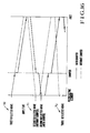
- Fig. 16 is a graph showing the attenuation state of the ultrasonic vibrations.
- the ultrasonic vibrations generated by the piezoelectric elements 1161 to 1166 are transmitted as ultrasonic signals to the strings 151 to 156 and propagate through the strings 151 to 156 toward the frets 13 n to 131.
- the ultrasonic signals are damped by the damping means 155 at a predetermined ratio. Each damped ultrasonic signal is then reflected by one of the frets 131 to 13 n to generate a primary echo.
- the primary echo is damped again by the damping means 155 before it reaches the corresponding one of the piezoelectric elements 1161 to 1166.
- the ultrasonic vibrations are damped by the damping means 155 twice while they reciprocate between the piezoelectric elements 1161 to 1166 and the frets 131 to 13 n , thereby, reducing the amplitudes of the ultrasonic vibrations.
- the decreases in amplitudes occur in the secondary echo and the subsequent echoes of higher orders based on the primary echo.
- the difference between the amplitudes of the ultrasonic signal and the echo becomes typical when the order of echoes is increased.
- the fret discriminator 37 can easily discriminate the reflection signal S1 based on the primary echo from undesirable noise. Therefore, the fret which caused generation of the echo can be accurately discriminated. Since the echoes of higher orders are rapidly damped, the interval of the drive pulses P1 can be shortened. Therefore, the resolution of the fret position discrimination can be improved.
- the above embodiment exemplifies an electronic stringed instrument using piezoelectric elements for ultrasonic transmission and reception.
- the present invention is applicable to an electronic musical instrument wherein transmitting piezoelectric elements are arranged in units of frets, and the ultrasonic signals transmitted from the transmitting piezoelectric elements to the strings are received by receiving piezoelectric elements so as to convert the echoes into electrical signals.
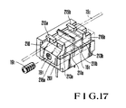
- a piezoelectric element mounted on a bridge may be arranged, as shown in Fig. 17.
- a bridge 201 having a piezoelectric element 161 will be exemplified.
- the bridge 201 has a substantially C-shaped groove 210 open upward from one of the side walls thereof in the direction toward which a screw 191 is threadably engaged.
- a plate-like piezoelectric element 161 having a rectangular section is disposed at the center of the groove 210.
- Conductive rubber members 211a and 211b are located in contact with both ends of the piezoelectric element 161.
- Leaf electrodes 213a and 213b are arranged in contact with the rubber members 211a and 211b, respectively.
- String seat members 216a and 216b are disposed outside the leaf electrodes 213a and 213b.
- the string seat members 216a and 216b have string seats 215a and 215b for receiving the string 151 and tightly hold the piezoelectric element 161, the rubber members 211a and 211b, and the leaf electrodes 213a and 213b so as to constitute an integral body.
- the legs of the leaf electrodes 213a and 213b extend downward through the holes formed in the bottom of the bridge 201 and are connected to a printed circuit board (not shown) disposed along the lower surface of the bridge holder.
- the lower surfaces of the rubber member 211a, the piezoelectric element 161, and the rubber member 211b are placed on a projection extending on the bottom of the bridge 201.
- the respective components are in contact with a screw extending from the lower surface side of the bridge holder through the holes of the bridge holder and the bridge and are fixed in position on the projection.
- the vibrations are transmitted to the string seat members 216a and 216b through the rubber members 211a and 211b, and the electrodes 213a and 213b.
- Ultrasonic vibrations are transferred from the string seats 215a and 215b to the string 151.
- the ultrasonic vibrations are reflected by the fret to generate an echo.
- the echo is transmitted to the piezoelectric element 161 in the reverse order and is converted into an electrical signal.
Landscapes
- Physics & Mathematics (AREA)
- Engineering & Computer Science (AREA)
- Acoustics & Sound (AREA)
- Multimedia (AREA)
- Electrophonic Musical Instruments (AREA)
Claims (17)
- Ein elektronisches Saitenmusikinstrument, bestehend aus:- einem Instrumentenkörper (11);- einer Saite (15₁ - 15₆), die über den Instrumentenkörper (11) gespannt ist;- eine Vielzahl von Bünden (13₁ - 13n), die auf dem Instrumentenkörper (11) und unterhalb der Saite (15₁ - 15₆) vorgesehen sind, so daß das Niederdrücken der Saite seitens des Spielers einen Kontakt zwischen der Saite und einem oder einigen der Vielzahl von Bünden hervorruft,
gekennzeichnet durch- Ultraschall-Sende/Empfangseinrichtungen (16₁ - 16₆), die auf dem Instrumentenkörper (11) vorgesehen und mit einem bestimmten Punkt der Saite gekoppelt sind, um eine Ultraschallwelle zu erzeugen, wenn ein erstes elektrisches Signal erzeugt wird, so daß sich die Ultraschallwelle über die Saite (15₁ - 15₆) zu dem Bund (13₁ - 13n) unter den die Saite berührenden Bünden oder Bund fortpflanzt, der dem bestimmten Punkt am nächsten liegt, um eine Echowelle zu empfangen, die eine von dem nächstgelegenen Bund reflektierte Welle der Ultraschallwelle ist, und ein zweites elektrisches Signal auf der Grundlage der Echowelle zu erzeugen; und- eine mit den Ultraschall-Sende/Empfangseinrichtungen (16₁ - 16₆) verbundene Bundunterscheidungseinrichtung (22) zum Unterscheiden des nächstliegenden Bundes unter der Vielzahl von Metallbünden entsprechend einer Zeitdifferenz zwischen der Erzeugung der Ultraschallwelle und dem Empfang der Echowelle auf der Basis des ersten und zweiten elektrischen Signals und zum Erzeugen eines Bundsignals (KC), das den nächstgelegenen Bund repräsentiert. - Ein elektronisches Saitenmusikinstrument nach Anspruch 1,
ferner aufweisend:
eine Dämpfungseinrichtung (155) zum Dämpfen einer Ultraschallschwingung der Saite (15₁ - 15₆) in einem vorbestimmten Verhältnis, so daß eine weitere Echoschwingung, die durch eine Reflektion einer Echoschwingung von dem nächstgelegenen Bund erzeugt wird, im wesentlichen beseitigt werden kann, wobei die Ultraschallschwingung und die Echoschwingung von der Ultraschallwelle bzw. der Echowelle hervorgerufen werden. - Ein elektronisches Saitenmusikinstrument nach Anspruch 1 oder 2,
bei dem die Ultraschall-Sende/Empfangseinrichtungen (16₁ - 16₆; 116₁ - 116₆) ein piezoelektrisches Wandlerelement einschließen, das zusätzlich ein drittes elektrisches Signal auf der Basis von durch das Zupfen der Saite (15₁ - 15₆) seitens des Spielers hervorgerufenen Saitenschwingungen erzeugt, wobei das dritte elektrische Signal einer Zupfdaten-Erzeugungseinrichtung (141) zum Erzeugen von Zupfdaten zugeführt wird. - Ein elektronisches Saitenmusikinstrument nach einem der Ansprüche 1 bis 3,
bei dem der Instrumentenkörper (11) ein Körperteil, ein Halsteil und ein Kopfteil aufweist, wobei das Halsteil zwischen dem Kopfteil und dem Körperteil angeordnet und die Saite (15₁ - 15₆) zwischen dem Körperteil und dem Kopfteil gespannt ist. - Ein elektronisches Saitenmusikinstrument nach Anspruch 4,
ferner aufweisend- einen Saitenhalter (14), der am Kopfteil zum Befestigen eines der Enden der Saite (15₁ - 15₆) angebracht ist, und- einen Dämpfer (23), der zwischen den auf dem Körperteil vorgesehenen Ultraschall-Sende/Empfangseinrichtungen (16₁ - 16₆) und dem Saitenhalter zum Dämpfen einer Schwingung der Saite vorgesehen ist, die durch das Zupfen der Saite seitens des Spielers erzeugt wird. - Ein elektronisches Saitenmusikinstrument nach Anspruch 4 oder 5,
ferner aufweisend- einen Abstimmwirbel (12a), der am Kopfteil zum Befestigen eines der Enden der Saite (15₁ - 15₆) vorgesehen ist; und- einen Dämpfer (24), der zwischen dem Abstimmwirbel (12a) und dem dem Kopfteil am nächsten gelegenen Bund (13₁ - 13₆) zum Dämpfen einer Schwingung der Saite angeordnet ist, die durch das Zupfen der Saite seitens des Spielers erzeugt wird. - Ein elektronisches Saitenmusikinstrument nach einem der Ansprüche 4 bis 6,
dadurch gekennzeichnet,
daß die Vielzahl von Metallbünden (13₁ - 13₆) auf dem Halsteil in einer Reihe angeordnet sind. - Ein elektronisches Saitenmusikinstrument nach einem der Ansprüche 1 bis 7,
ferner aufweisend einen Tongenerator (47), der mit der Bundunterscheidungseinrichtung (22) zum Erzeugen eines Tonsignals verbunden ist, das eine vom Bundsignal bestimmte Tonhöhe aufweist. - Ein elektronisches Saitenmusikinstrument nach einem der Ansprüche 1 bis 8,
ferner aufweisend eine Schwingungserfassungseinrichtung (21₁ - 21₆), die zwischen den Ultraschall-Sende/Empfangseinrichtungen (16₁ - 16₆) und dem Bund (13₁ - 13₆) unter der Vielzahl von Metallbünden angeordnet ist, der den Ultraschall-Sende/Empfangseinrichtungen am nächsten liegt, um die durch das Zupfen der Saite seitens des Spielers erzeugte Schwingung der Saite (15₁ - 15₆) zu erfassen und ein auf der erfaßten Schwingung beruhendes Erfassungssignal zu erzeugen. - Ein elektronisches Saitenmusikinstrument nach Anspruch 8 oder 9,
bei dem der Tongenerator (47) mit der Schwingungserfassungseinrichtung (21₁ - 21₆) zum Erzeugen eines Tonsignals in Erwiderung auf das Erfassungssignal verbunden ist. - Ein elektronisches Saitenmusikinstrument nach Anspruch 1,
bei dem die Ultraschall-Sende/Empfangseinrichtungen (16₁ - 16₆) zum Umwandeln einer Schwingung der Saite in ein Schwingungssignal dient, wobei die Schwingung eine von der Echowelle erzeugte Echoschwingung und eine durch das Zupfen der Saite seitens des Spielers erzeugte Zupfschwingung aufweist. - Ein elektronisches Saitenmusikinstrument nach Anspruch 11,
ferner aufweisend eine Schwingungserfassungseinrichtung (141), die mit den Ultraschall-Sende/Empfangseinrichtungen (16₁ - 16₆) verbunden ist und ein Tiefpaßfilter (113) aufweist, das das Schwingungssignal empfängt und lediglich die Zupfschwingung entnimmt. - Ein elektronisches Saitenmusikinstrument nach Anspruch 11 oder 12,
bei dem die Bundunterscheidungseinrichtung ein Hochpaßfilter (111) aufweist, das das Schwingungssignal empfängt und eine Komponente der Zupfschwingung entnimmt. - Ein elektronisches Saitenmusikinstrument nach einem der Ansprüche 1 bis 13,
ferner aufweisend- einen Steghalter (17), der auf dem Instrumentenkörper (11) befestigt ist;- Stege (20₁ - 20₆), die auf dem Steghalter befestigt und parallel zu den Saiten (15₁ - 15₆) bewegbar sind; und- ein auf jedem Steg (20₁ - 20₆) zum Senden und Empfangen der Ultraschallwelle befestigtes Sende/Empfangselement (16₁ - 16₆). - Ein elektronisches Saitenmusikinstrument nach Anspruch 14,
bei dem das Sende/Empfangselement ein piezoelektrisches Element aufweist. - Ein elektronisches Saitenmusikinstrument nach Anspruch 14,
bei dem der Steg (20₁) ein piezoelektrisches Element (16₁), leitende Gummielemente (211a, 211b), die in engem Kontakt mit den beiden Seiten des piezoelektrischen Elements stehen, und Blattelektroden (213a, 213b) aufweist, die in engem Kontakt mit den beiden Enden der leitenden Gummielemente stehen. - Ein elektronisches Saitenmusikinstrument nach einem der Ansprüche 3 bis 16,
bei dem die Zupfdaten Daten einschließen, die die Stärke und/oder Zeitdauer des Zupfens des Spielers wiedergeben.
Applications Claiming Priority (6)
| Application Number | Priority Date | Filing Date | Title |
|---|---|---|---|
| JP240138/85 | 1985-10-26 | ||
| JP60240138A JPS6299790A (ja) | 1985-10-26 | 1985-10-26 | 電子弦楽器 |
| JP61068947A JPH0631952B2 (ja) | 1986-03-25 | 1986-03-25 | 電子弦楽器 |
| JP4505386U JPH0624877Y2 (ja) | 1986-03-25 | 1986-03-25 | 電子弦楽器 |
| JP45053/86U | 1986-03-25 | ||
| JP68947/86 | 1986-03-25 |
Publications (3)
| Publication Number | Publication Date |
|---|---|
| EP0227906A2 EP0227906A2 (de) | 1987-07-08 |
| EP0227906A3 EP0227906A3 (en) | 1989-02-08 |
| EP0227906B1 true EP0227906B1 (de) | 1992-09-09 |
Family
ID=27292102
Family Applications (1)
| Application Number | Title | Priority Date | Filing Date |
|---|---|---|---|
| EP86114768A Expired - Lifetime EP0227906B1 (de) | 1985-10-26 | 1986-10-24 | Elektronisches Saitenmusikinstrument |
Country Status (3)
| Country | Link |
|---|---|
| US (1) | US4723468A (de) |
| EP (1) | EP0227906B1 (de) |
| DE (1) | DE3686707T2 (de) |
Cited By (1)
| Publication number | Priority date | Publication date | Assignee | Title |
|---|---|---|---|---|
| DE102008044933B3 (de) * | 2008-08-29 | 2010-04-22 | Uli Gobbers | Laser PickUp |
Families Citing this family (31)
| Publication number | Priority date | Publication date | Assignee | Title |
|---|---|---|---|---|
| US4911053A (en) * | 1986-07-04 | 1990-03-27 | Casio Computer | Electronic stringed instrument having a string trigger switch |
| US5040447A (en) * | 1986-09-10 | 1991-08-20 | Casio Computer Co., Ltd. | Electronic stringed instrument with fingering operating data memory system and navigate display device |
| US5018428A (en) * | 1986-10-24 | 1991-05-28 | Casio Computer Co., Ltd. | Electronic musical instrument in which musical tones are generated on the basis of pitches extracted from an input waveform signal |
| US4919031A (en) * | 1987-03-24 | 1990-04-24 | Casio Computer Co., Ltd. | Electronic stringed instrument of the type for controlling musical tones in response to string vibration |
| DE3881930T2 (de) * | 1987-04-03 | 1993-10-07 | Yamaha Corp | Elektronisches Musikinstrument und Saitenpositionsdetektor dazu. |
| US4873904A (en) * | 1987-04-22 | 1989-10-17 | Yamaha Corporation | Electronic musical instrument having playing and parameter adjustment modes |
| JP2778645B2 (ja) * | 1987-10-07 | 1998-07-23 | カシオ計算機株式会社 | 電子弦楽器 |
| US4951546A (en) * | 1988-01-14 | 1990-08-28 | Yamaha Corporation | Electronic stringed musical instrument |
| KR920004102B1 (ko) * | 1988-03-22 | 1992-05-25 | 가시오 게이상기 가부시끼가이샤 | 전자 현악기 |
| US5033353A (en) * | 1988-04-14 | 1991-07-23 | Fala Joseph M | Note sensing in M.I.D.I. guitars and the like |
| JP2797112B2 (ja) * | 1988-04-25 | 1998-09-17 | カシオ計算機株式会社 | 電子弦楽器のコード判別装置 |
| JPH01160498U (de) * | 1988-04-25 | 1989-11-07 | ||
| US4951545A (en) * | 1988-04-26 | 1990-08-28 | Casio Computer Co., Ltd. | Electronic musical instrument |
| JP2615825B2 (ja) * | 1988-05-02 | 1997-06-04 | カシオ計算機株式会社 | 電子弦楽器 |
| JPH01177794U (de) * | 1988-06-03 | 1989-12-19 | ||
| US4991488A (en) * | 1988-08-12 | 1991-02-12 | Fala Joseph M | Acoustic detection of note bending in stringed M.I.D.I. compatible musical instruments |
| JPH0244789U (de) * | 1988-09-20 | 1990-03-28 | ||
| JPH02176792A (ja) * | 1988-12-28 | 1990-07-09 | Casio Comput Co Ltd | 電子弦楽器 |
| US5149904A (en) * | 1989-02-07 | 1992-09-22 | Casio Computer Co., Ltd. | Pitch data output apparatus for electronic musical instrument having movable members for varying instrument pitch |
| USH1503H (en) * | 1990-01-09 | 1995-12-05 | Threadgill; Irene C. | Cordless electric guitar |
| US5221159A (en) * | 1990-03-28 | 1993-06-22 | Environmental Improvement Technologies, Inc. | Subsurface contaminant remediation, biodegradation and extraction methods and apparatuses |
| US5669878A (en) * | 1992-01-30 | 1997-09-23 | Intravascular Research Limited | Guide wire for a catheter with position indicating means |
| GB2263641A (en) * | 1992-01-30 | 1993-08-04 | Intravascular Res Ltd | Determining catheter location |
| FR2694707B1 (fr) * | 1992-08-13 | 1994-12-23 | Aquafrance | Procédé de dépollution de fumée de chaudières à combustible liquide par refroidissement et lavage des fumées, et neutralisation des effluents. |
| DE4343411C2 (de) * | 1993-12-18 | 2001-05-17 | Blue Chip Music Gmbh | Gitarren-Signalanalyseeinrichtung |
| JP2805598B2 (ja) * | 1995-06-16 | 1998-09-30 | ヤマハ株式会社 | 演奏位置検出方法およびピッチ検出方法 |
| US6770807B1 (en) * | 2003-04-01 | 2004-08-03 | Allen P. Myers | Sound pickup device |
| US8450593B2 (en) * | 2003-06-09 | 2013-05-28 | Paul F. Ierymenko | Stringed instrument with active string termination motion control |
| US7462767B1 (en) | 2005-06-10 | 2008-12-09 | Swift Dana B | Stringed musical instrument tension balancer |
| JP2009516213A (ja) * | 2005-11-14 | 2009-04-16 | コットン,ギル | 弦楽器に結合されるセンサにより集められたデータから音を再生すると共にシンセサイザー制御データを生成するための方法及びシステム |
| US7598450B2 (en) * | 2007-04-19 | 2009-10-06 | Marcodi Musical Products, Llc | Stringed musical instrument with improved method and apparatus for tuning and signal processing |
Citations (1)
| Publication number | Priority date | Publication date | Assignee | Title |
|---|---|---|---|---|
| US4151775A (en) * | 1977-08-31 | 1979-05-01 | Merriman George W | Electrical apparatus for determining the pitch or fundamental frequency of a musical note |
Family Cites Families (8)
| Publication number | Priority date | Publication date | Assignee | Title |
|---|---|---|---|---|
| US2187611A (en) * | 1937-03-02 | 1940-01-16 | Miessner Inventions Inc | Method and apparatus for the production of music |
| US3519721A (en) * | 1968-03-21 | 1970-07-07 | Baldwin Co D H | Electropiano with plural piezoelectric pickups on unitary acoustic rail |
| US3619468A (en) * | 1970-03-05 | 1971-11-09 | Columbia Broadcasting Systems | Stringed musical instrument with piezoelectric transducer providing gate control and music signals |
| US4241430A (en) * | 1979-01-08 | 1980-12-23 | Douglas J. Kayem | Method and apparatus for determining the length of tubular members |
| US4248120A (en) * | 1979-05-29 | 1981-02-03 | Stewart Dickson | Stringed musical instrument with electrical feedback |
| CH656954A5 (de) * | 1981-10-30 | 1986-07-31 | Maag Zahnraeder & Maschinen Ag | Verfahren und anordnung zum auswerten von signalen aus einem ultraschallwegmesssystem. |
| US4584676A (en) * | 1982-03-15 | 1986-04-22 | Measurement Systems, Inc. | Method of and apparatus for pipe length measurement |
| US4597183A (en) * | 1983-02-24 | 1986-07-01 | Standard Oil Company (Indiana) | Methods and apparatus for measuring a length of cable suspending a well logging tool in a borehole |
-
1986
- 1986-10-23 US US06/922,688 patent/US4723468A/en not_active Expired - Fee Related
- 1986-10-24 DE DE8686114768T patent/DE3686707T2/de not_active Expired - Fee Related
- 1986-10-24 EP EP86114768A patent/EP0227906B1/de not_active Expired - Lifetime
Patent Citations (1)
| Publication number | Priority date | Publication date | Assignee | Title |
|---|---|---|---|---|
| US4151775A (en) * | 1977-08-31 | 1979-05-01 | Merriman George W | Electrical apparatus for determining the pitch or fundamental frequency of a musical note |
Cited By (1)
| Publication number | Priority date | Publication date | Assignee | Title |
|---|---|---|---|---|
| DE102008044933B3 (de) * | 2008-08-29 | 2010-04-22 | Uli Gobbers | Laser PickUp |
Also Published As
| Publication number | Publication date |
|---|---|
| EP0227906A3 (en) | 1989-02-08 |
| DE3686707T2 (de) | 1993-04-22 |
| EP0227906A2 (de) | 1987-07-08 |
| DE3686707D1 (de) | 1992-10-15 |
| US4723468A (en) | 1988-02-09 |
Similar Documents
| Publication | Publication Date | Title |
|---|---|---|
| US4723468A (en) | Electronic stringed instrument | |
| US5033353A (en) | Note sensing in M.I.D.I. guitars and the like | |
| KR920010919B1 (ko) | 전자 현악기 | |
| US4991488A (en) | Acoustic detection of note bending in stringed M.I.D.I. compatible musical instruments | |
| US4882965A (en) | Direction of bowing detection method and apparatus | |
| JPS6289995A (ja) | 楽器用の汎用ピツチ及び振幅計算器及び変換器 | |
| JPH0624877Y2 (ja) | 電子弦楽器 | |
| JPS6412392B2 (de) | ||
| JPH0624880Y2 (ja) | 電子弦楽器 | |
| JPH0624875Y2 (ja) | 電子弦楽器 | |
| JPH0624874Y2 (ja) | 電子弦楽器 | |
| JPS6412396B2 (de) | ||
| JPH0624879Y2 (ja) | 電子弦楽器 | |
| JPH068637Y2 (ja) | 電子弦楽器 | |
| JPH0631950B2 (ja) | 電子弦楽器 | |
| JPH0631951B2 (ja) | 電子弦楽器 | |
| JPH0626957Y2 (ja) | 電子弦楽器 | |
| CA1304141C (en) | Direction of bowing detection method and apparatus | |
| JPS6412395B2 (de) | ||
| JPH0626956Y2 (ja) | 電子弦楽器 | |
| JPH0631952B2 (ja) | 電子弦楽器 | |
| JPS62231293A (ja) | 電子弦楽器 | |
| JPH0641275Y2 (ja) | 電子弦楽器 | |
| JPS6412394B2 (de) | ||
| JP2746153B2 (ja) | 電子弦楽器 |
Legal Events
| Date | Code | Title | Description |
|---|---|---|---|
| PUAI | Public reference made under article 153(3) epc to a published international application that has entered the european phase |
Free format text: ORIGINAL CODE: 0009012 |
|
| AK | Designated contracting states |
Kind code of ref document: A2 Designated state(s): DE GB |
|
| 17P | Request for examination filed |
Effective date: 19870817 |
|
| PUAL | Search report despatched |
Free format text: ORIGINAL CODE: 0009013 |
|
| RAP1 | Party data changed (applicant data changed or rights of an application transferred) |
Owner name: YAMAHA CORPORATION |
|
| AK | Designated contracting states |
Kind code of ref document: A3 Designated state(s): DE GB |
|
| 17Q | First examination report despatched |
Effective date: 19910327 |
|
| GRAA | (expected) grant |
Free format text: ORIGINAL CODE: 0009210 |
|
| AK | Designated contracting states |
Kind code of ref document: B1 Designated state(s): DE GB |
|
| REF | Corresponds to: |
Ref document number: 3686707 Country of ref document: DE Date of ref document: 19921015 |
|
| PLBE | No opposition filed within time limit |
Free format text: ORIGINAL CODE: 0009261 |
|
| STAA | Information on the status of an ep patent application or granted ep patent |
Free format text: STATUS: NO OPPOSITION FILED WITHIN TIME LIMIT |
|
| 26N | No opposition filed | ||
| PGFP | Annual fee paid to national office [announced via postgrant information from national office to epo] |
Ref country code: GB Payment date: 19951016 Year of fee payment: 10 |
|
| PGFP | Annual fee paid to national office [announced via postgrant information from national office to epo] |
Ref country code: DE Payment date: 19951026 Year of fee payment: 10 |
|
| PG25 | Lapsed in a contracting state [announced via postgrant information from national office to epo] |
Ref country code: GB Effective date: 19961024 |
|
| GBPC | Gb: european patent ceased through non-payment of renewal fee |
Effective date: 19961024 |
|
| PG25 | Lapsed in a contracting state [announced via postgrant information from national office to epo] |
Ref country code: DE Effective date: 19970701 |