EP0227911A2 - Optisches Luftdatenmesssystem - Google Patents
Optisches Luftdatenmesssystem Download PDFInfo
- Publication number
- EP0227911A2 EP0227911A2 EP86115064A EP86115064A EP0227911A2 EP 0227911 A2 EP0227911 A2 EP 0227911A2 EP 86115064 A EP86115064 A EP 86115064A EP 86115064 A EP86115064 A EP 86115064A EP 0227911 A2 EP0227911 A2 EP 0227911A2
- Authority
- EP
- European Patent Office
- Prior art keywords
- radiation
- fluorescence
- intensity
- aircraft
- air
- Prior art date
- Legal status (The legal status is an assumption and is not a legal conclusion. Google has not performed a legal analysis and makes no representation as to the accuracy of the status listed.)
- Withdrawn
Links
Images


Classifications
-
- G—PHYSICS
- G01—MEASURING; TESTING
- G01N—INVESTIGATING OR ANALYSING MATERIALS BY DETERMINING THEIR CHEMICAL OR PHYSICAL PROPERTIES
- G01N21/00—Investigating or analysing materials by the use of optical means, i.e. using sub-millimetre waves, infrared, visible or ultraviolet light
- G01N21/62—Systems in which the material investigated is excited whereby it emits light or causes a change in wavelength of the incident light
- G01N21/63—Systems in which the material investigated is excited whereby it emits light or causes a change in wavelength of the incident light optically excited
- G01N21/64—Fluorescence; Phosphorescence
- G01N21/6402—Atomic fluorescence; Laser induced fluorescence
-
- G—PHYSICS
- G01—MEASURING; TESTING
- G01P—MEASURING LINEAR OR ANGULAR SPEED, ACCELERATION, DECELERATION, OR SHOCK; INDICATING PRESENCE, ABSENCE, OR DIRECTION, OF MOVEMENT
- G01P5/00—Measuring speed of fluids, e.g. of air stream; Measuring speed of bodies relative to fluids, e.g. of ship, of aircraft
- G01P5/26—Measuring speed of fluids, e.g. of air stream; Measuring speed of bodies relative to fluids, e.g. of ship, of aircraft by measuring the direct influence of the streaming fluid on the properties of a detecting optical wave
-
- G—PHYSICS
- G06—COMPUTING OR CALCULATING; COUNTING
- G06F—ELECTRIC DIGITAL DATA PROCESSING
- G06F9/00—Arrangements for program control, e.g. control units
- G06F9/06—Arrangements for program control, e.g. control units using stored programs, i.e. using an internal store of processing equipment to receive or retain programs
- G06F9/30—Arrangements for executing machine instructions, e.g. instruction decode
- G06F9/38—Concurrent instruction execution, e.g. pipeline or look ahead
- G06F9/3836—Instruction issuing, e.g. dynamic instruction scheduling or out of order instruction execution
- G06F9/3842—Speculative instruction execution
-
- G—PHYSICS
- G01—MEASURING; TESTING
- G01N—INVESTIGATING OR ANALYSING MATERIALS BY DETERMINING THEIR CHEMICAL OR PHYSICAL PROPERTIES
- G01N21/00—Investigating or analysing materials by the use of optical means, i.e. using sub-millimetre waves, infrared, visible or ultraviolet light
- G01N21/17—Systems in which incident light is modified in accordance with the properties of the material investigated
- G01N2021/1793—Remote sensing
Definitions
- the invention relates generally to the field of air data measurement systems and more particularly to an optical measurement system which induces fluorescence in one or more particular types of air molecules at the sample location to determine other related air data parameters such as density, pressure, and/or barometric altitude.
- the system also creates three-dimensional patterns of fringes at a remote sample location for the purpose of measuring the velocity of aerosol particles at that location as a function of the radiation which they scatter back to the device.
- the known prior art does not teach or show how fluorescent emissions, and, in particular, how the decay characteristics of such fluorescent emissions once the fluorescent energy source has been interrupted, may be utilized to calculate air data parameters such as the relative density of a particular molecular species or, if the fluorescing molecules represent a known percentage of the atmosphere, the density, pressure and barometric altitude of the atmosphere at the elevation at which the measurement is being made.
- a fluorescent gas measurement device for measuring a gas parameter at a sample location comprising: first means for inducing at least one molecular species within the gas at said sample location to emit fluorescence, second means for measuring the intensity of said fluorescence, and third means responsive to the measured fluorescence intensity for computing said parameter therefore, characterised in that said gas is air and said sample location is remote from said device, and said device is adapted to measure a parameter related to the concentration of said molecular species in said air, such as density, pressure and/or barometric altitude.
- the atmosphere contains many naturally occurring aerosols having a diameter on the order of from 0.1 to 10 micrometers.
- aerosols are pollen and dust that naturally occur in the atmosphere. These aerosols tend to follow the motion of the atmosphere in which they are entrained and hence by observing the motion of such particles, it is possible to measure the velocity of the surrounding airstream.
- optical techniques have also been utilized to measure wind.
- One such technique employed scattered sunlight as a source and cross- correlated the outputs of two radiometers having intersecting fields of view. Against localized flumes, such as the flume from a smokestack, it produces satisfactory results.
- a more sophisticated type of optical device measured the Doppler shift in light scattered by particles within the moving fluid to measure velocity along the system's optical axis.
- fringe laser velocimeter which measured a velocity component transverse to the instrument's line of sight by detecting the movement of aerosol particles through a layered pattern of interference fringes created by two intersecting beams of coherent laser light.
- Another optical technique relied upon variations in refractive index moving with the wind across the line of sight of the instrument, detecting such variation by means of a so-called double-ended system having separated source and receiver.
- the known prior art does not teach or suggest how the above-mentioned optical and other related techniques may be utilized to provide a compact radiation fringe velocimeter for measuring in three dimensions.
- the known prior art suggests that at least one velocity component-that parallel to the velocimeter's main axis-should be measured by the above-described Doppler method which requires that the coherency of the radiation be maintained even after it has been scattered back towards the velocimeter where it still must be combined with unscattered light from a referenced source related in frequency and coherency to the radiation impinging upon the object, thus requiring a radiation source that is coherent and which is capable of maintaining such coherency over relatively long distances.
- the known devices which satisfy such a criterion employ a CO 2 laser having a relatively long wavelength that is not optimal for the relatively small aerosol particles that are naturally found in the earth's atmosphere.
- the known prior art does not teach or suggest how air data measurements that are critical to the operation of an aircraft (such as true air speed, side slip, angle of attack, air density, air pressure, and/or barometric altitude) can be simply and reliably measured by means of an accurate and reliable measurement device free of any Pitot tubes, pressure ports or protrusions into the airstream.
- two novel optical subsystems namely, a radiation fringe velocimeter subsystem for measuring in three dimensions and a subsystem for inducing fluorescence in selected air molecules and thereby determining air density related parameters, are combined into a single system which permits various important parameters associated with the operation of an aircraft to be measured by means of purely optical techniques at a sample location at a sufficient distance from the aircraft (or any physical attachment thereto) so that the measurements will not be subject to systemic errors such as those caused by air compression effects and airflow disturbances, and which does not require that any Pitot tubes, pressure ports or other similar mechanical devices protrude into the airstream where the measurements are to be made.
- the combined system contains a laser or other suitable radiation source (or sources) as well as an optical arrangement for transmitting the radiation from the laser to a sample volume in order both to form linearly independent sets of radiation fringes at the sample location as well as to focus the radiation at the sample location so as to cause selected air molecules to fluoresce.
- the device also contains an optical receiving arrangement for focusing backscattered radiation and fluorescent emissions from the sample volume onto one or more photodetectors.
- the radiation that forms the pattern of fringes originates from a single laser having an output spectral content that results not only in a significant portion of the radiation being backscattered by the type of aerosol particles that will normally be encountered at the operational altitudes of the aircraft but which will also result in substantial fluorescence of particular molecules which comprise a known percentage of the earth's atmosphere of which Nitrogen (N 2 ) is the most prevalent.
- both radiation sources are provided and the spectral content of the radiation used to create the fringe patterns is different from that used to fluoresce the air molecules.
- both sources of radiation may be caused to propagate along a common optical path leading to the same sample volume in the external free airstream, thus permitting common receiving optical elements to function as part of both subsystems.
- the resultant backscattered radiation containing the velocity information may differ in spectral content from the fluorescent emissions containing the density (pressure) information.
- two separate photodetectors may be each provided with a suitable optical filter such that the output of one photodetector is indicative of the present intensity of the fluorescence of the selected air molecules (and thus of air pressure and density) and the output of the other photodetector is indicative of the changing intensity of the backscattered radiation caused by the movement of aerosol particles relative to the sample volume (and thus of air speed, etc.).
- a radiation source such as a Q-switched laser
- a single photodetector that is responsive both to backscattered radiation and to fluorescent re-emissions, since the backscattered radiation will cease as soon as the radiation is turned off, but the fluorescent emissions will decay exponentially.
- FIG. 1 reflects an exemplary embodiment of the present invention installed aboard a supersonic aircraft (10).
- a sample volume (12) is defined by the intersection of the laser beams (14) at the focal point of the transmitting optical subsystem, and is located at some distance removed from the nearest surface (16) of the aircraft (10) such that the sample volume (12) is in fact located in a portion of the airstream undisturbed by the supersonic shock wave (18).
- output of the receiving optical subsystem (20) is preferably conditioned by a data processor (22) prior to display by the instrumentation system (24) and utilization by the aircraft's avionics (26).
- the data processor - (22) also has, as another input, a temperature signal provided by a conventional temperature sensing subsystem (28). (A value for temperature is required to derive the pressure of a gas from its density.)
- the system in effect uses changes in induced fluorescence to measure optically the density of the air mass and changes in the backscattered radiation as the scattering particle moves relative to interference fringes to measure optically the velocity of the air.
- Air density (D) combined with static temperature (T,) can be used to determine pressure altitude (P,): where R is the ideal gas constant.
- Static temperature (T,) is related to total temperature (T t ) and Mach number (M) as follows:
- FIG. 2 illustrates graphically such an exponential relationship between Intensity (I) and Time (t) in which it can be seen that at equally spaced intervals of time (e.g., "(t, -t2)") following the interruption of the energy source at time to, the intensity is successively reduced by a constant factor.
- the collision rate constant is merely the mean collision rate between the excited molecule and all other molecules present.
- n M , n A are the number densities of species M and A respectively
- d MA is the average diameter of molecules M and A
- k is the Boltzmann constant
- T the absolute temperature
- m * MA is the reduced mass of molecules M and A
- the mean fluorescence lifetime can be determined and the density can then be computed from the relation between mean lifetime and the collision rate calculated above.
- the above-described technique has several advantages, including sensitivity to even short-lived fluorescence at low altitudes (high density, pressure), and freedom from calibration of the photodetector for absolute intensity measurement, since only relative intensity is used.
- a first embodiment of the optical subsystem (20) of the present invention comprises a high intensity light source (32) of coherent monofrequency radiation - (e.g., a primary light beam (34) produced by a laser operated in single-line mode), a beam splitting device (36) for generating a first plurality of radiation beams, a modulating device (38) for generating from said first plurality of beams a second plurality of beams each having a distinguishing characteristic, a focusing device in the form of a transmit/receive window lens (40) for forming three separately identifiable sets of non-orthogonal, but linearly independent, three-dimensional patterns of fringe planes, and a detector device (42).
- a high intensity light source of coherent monofrequency radiation - (e.g., a primary light beam (34) produced by a laser operated in single-line mode)
- a beam splitting device (36) for generating a first plurality of radiation beams
- a modulating device (38) for generating from said first plurality of beams a second plurality of
- the primary light beam (34) which in the case of the illustrated embodiment may be a coherent monofrequency light beam generated by the laser - (32), is split such that approximately thirty percent of the beam is transmitted as a first secondary beam (44), thirty-five percent is transmitted as a second secondary beam (46), and thirty-five percent as a third secondary beam (48).
- the secondary beams (44, 46, 48) are thus of substantially equal intensity and are arranged more or less parallel to one another and spaced at approximately equal angular intervals about, and at approximately equal radial distances from, a central axis (50).
- the secondary beams (44, 46, 48) impinge on a modulating array of ac p ustooptic cells (38) at so-called "Bragg angles" 8 determined in accordance with the equation where ?. is the wavelength of the entry beam and S is the wavelength of the acoustic waves within the cell.
- ?. is the wavelength of the entry beam
- S is the wavelength of the acoustic waves within the cell.
- the acoustic waves in the deflection medium inside each of the cells effectively set up a phase diffraction grating moving with the velocity of sound within the medium and having a grating spacing equal to the sound wavelength. Since the incoming beam enters the cell at the Bragg angle, a substantial percentage of the beam is diffracted from the exit side of the cell in a first order diffracted beam that is deflected from the incident light beam by an angle -2 B . This deflected beam is subjected to a slight frequency displacement Af as a result of a Doppler effect occasioned by the movement relative to the moving acoustic wave front; the deflected beam is also phase modulated in accordance with the frequency and amplitude of the sound wave.
- each of the three cells is driven at a different characteristic frequency; accordingly, each cell has its own individual Bragg angle (B ⁇ , B ⁇ , B ⁇ ") at which the incoming light beam should enter.
- B ⁇ , B ⁇ , B ⁇ individual Bragg angle
- FIG. 2 in addition to the three diffracted beams - (52, 54, 56) exiting from the three respective Bragg cells, three respective undeflected beams (58, 60, 62) are also present. These three undeflected beams represent the portion of the respective incoming beams (44, 46, 48) that were not diffracted (and modulated in frequency and phase) by the corresponding respective Bragg cells.
- each pair having a substantially unshifted beam (58, 60, 62) (i.e., a zero order diffraction) and a modulated beam (52, 54, 56) (the above-mentioned deflected beams).
- the plane containing the two diverging beams (56, 62) of third beam pair (68) is oriented vertically (i.e., in the X-Z plane).
- the planes containing the first pair of beams (52, 58) and the second pair of beams (54, 60) subtend angles of -120° and +120°, respectively, with respect to the vertical (X-Y) plane.
- the window lens (40) as shown in the particular embodiment of FIG. 3 comprises a front lens element (70) and a rear lens element (72); the output beam (14) comprises a first converging beam pair (74), a second converging beam pair - (76) and a third converging beam pair (78).
- the first converging beam pair (74) is in fact comprised of a first outer beam (80) corresponding to the undeflected input beam (58) and a first inner beam (82) corresponding to the deflected beam (52) of the first input beam pair (64).
- the inner beam (82) and the outer beam (84) in fact are both directed toward the central axis (50) of the window lens (40) so that all three converging beam pairs (74, 76, 78) will all converge within the same sample region (12).
- the second converging output beam pair (76) consists of a second outer beam (84) and a second inner beam (80) corresponding respectively to beams (60, 54) of the second diverging beam pair (66), while the third converging beam pair (78) consists of a third outer beam (88) and a third inner beam (90) corresponding to diverging beams (62, 56).
- FIG. 4 is an enlarged cross-sectional view of one set of moving fringe patterns formed by the intersection of two beams of a convergent pair - (e.g., beams (80, 82) of the first converging pair - (74)).
- Each bright or dark fringe may be said to occur in a respective bright or dark fringe plane perpendicular to the plane containing the two intersecting beams and generally parallel to the bisector of the angle of intersection of the beam pair, the orientation of the fringe planes within such a fringe pattern being defined by a so-called fringe plane normal vector (e.g., vector (92)) disposed perpendicular to the fringe planes.
- fringe plane normal vector e.g., vector (92)
- the attitude or position of the three bisectors and of the three planes respectively, containing the three beam pairs are selected such that the three corresponding fringe normal vectors (e.g., vector - (92)) are disposed non-orthogonal with respect to each other and are linearly independent of one another (i.e., all three normal vectors do not lie on a common plane). Accordingly, when a small physical object (such as a particle of dust or similar aerosol) traverses the three sets of fringe patterns formed by the three beam pairs, a velocity component of the object may be measured in the direction of each of the three fringe normal vectors providing a set of three (non-orthogonal) velocity components in three dimensions.
- a small physical object such as a particle of dust or similar aerosol
- the velocity component produced by each beam pair may be measured perpendicular to the bisector of the angle subtended by, and in the plane containing, the beams of the pair (i.e., measured along the normal to the interference pattern fringe planes formed by that beam pair).
- the coherent radiation from the laser (32) is scattered by the entity with an amplitude that depends on the location of the entity relative to the nearest bright fringe.
- the scattered light is refocused by the whole of the window lens (40) (except for the segments (106) onto the photodetector (42).
- the detector (42) provides a processor with a composite output signal representing all three non-orthogonal components of the velocity of the entity through the fringes.
- the processor then separates the signal into the three linearly independent, non-orthogonal velocity components corresponding to the three normal vectors, and then transforms these individual non-orthogonal velocity components to measurements in a desired orthogonal frame of reference.
- the illustrated device will function even if the three sets of fringe patterns associated respectively with the three beam pairs (74, 76, 78) do not actually overlap but are merely located in the same general spatial volume so that the window lens (40) may still gather light from all three sets of fringe patterns onto a single detector (42).
- the window lens (40) may still gather light from all three sets of fringe patterns onto a single detector (42).
- all three sets of fringe patterns overlap one another, there is a greater probability of measuring all three linearly independent components of the velocity of a single aerosol particle, since any particle having an effective cross section larger than the wavelength of the incident radiation will scatter at least some light back to the detector (42) from each of the three sets of fringe patterns.
- Peaks (94, 96) correspond to maximum scatter at the central bright fringe regions (98, 100) (FIG. 4) and the troughs (102, 104) (FIG. 5) correspond to substantially no scatter at the corresponding dark fringe regions (106, 108) (FIG. 4).
- the optical system (20) of the three-dimensional fringe velocimeter subsystem components may also function as the optical subsystem of a fluorescent air data measurement subsystem arranged coaxially therewith.
- the propagation of energy from the fluorescent air data measurement subsystem to the sample region (12) is switched on and off (preferably by means of an internal Q-switch associated with the laser (32)) in accordance with the timing diagram of FIG. 6.
- the laser (32) is preferably a continuous wave type of laser that may be operated at a relatively high duty factor-as indicated in FIG. 6, a 20 millisecond "On” (110) followed by a 10 microsecond "Off” (112).
- the optical subsystem (20) may be generating the three sets of non-orthogonal linearly independent moving interference fringe planes in accordance with the requirements of the velocity measuring subsystem.
- the radiation source (32) is switched off and the photodetector (42) measures only the exponential decay of the fluorescent emissions originating from the sample region (12).
- the radiation source for inducing the fluorescence originates with the laser - (32) which, as noted previously, has an output in the form of a beam (34) that is split into three secondary beams (44, 46, 48) which are modulated to form three beam pairs (54, 56, 58) resulting in a total of six individual beams which are all focused by front lens (70) onto sample region (12).
- the laser - (32) which, as noted previously, has an output in the form of a beam (34) that is split into three secondary beams (44, 46, 48) which are modulated to form three beam pairs (54, 56, 58) resulting in a total of six individual beams which are all focused by front lens (70) onto sample region (12).
- the output of the photodetector (42) which has its field of view concentrated on sample region (12) will be a function of the intensity of the fluorescence.
- the velocimeter function of the apparatus is dependent only upon the frequency with which the amplitude of the output from the photodetector (42) is modulated.
- the fact that a constant fluorescence phenomenon is occurring in the same region of space at which the aerosol particles are crossing from a dark interference fringe plane to a bright interference fringe plane or vice versa will only serve to provide a constant bias to the amplitude of the photodetector's output and will not affect the frequency spectrum from which the velocity measuring subsystem extracts the velocity data.
- the fluorescent re-emissions radiating from the sample region (12) towards the window lens (40) are focused by the combination of the front lens - (70) and the rear lens (72) onto the photodetector - (42).
- the frequency of the light emitted by the laser (32) it is possible to cause only one particular molecular species within the atmosphere to fluoresce with sufficient intensity for such fluorescence to affect the output of the detector (42).
- the molecular species of interest is Nitrogen (N2) (and in that regard, it should be remarked that the proportion of N z within the atmosphere is relatively constant, at least at the elevations at which aircraft are normally operated, and therefore the density of N2 within a given sample of atmospheric air will be a reliable indication of the air pressure and barometric altitude in the vicinity of the sample)
- the N 2 molecules in the sample region, rather than other species not of interest may be caused to fluoresce by means of, for example, an N2 laser.
- a window lens (40) is shown as being the means for projecting the six laser radiation beams and three sets of interference fringe plane patterns onto the detection volume (12) and for focusing the backscattered radiation and fluorescent re-emissions from the detection volume onto the detection de- . vice (42), it would be a simple matter well within the level of skill of the average artisan to substitute other functionally equivalent means for projecting and/or focusing, such as a concave reflective surface of optical quality formed on the front of a suitably shaped support.
- the window function of the lens (40) could be satisfied by means of a suitable thickness of a transparent material, possibly provided with self-cleaning segments in which a stream of pressurized air from inside the aircraft is directed across the critical portions of the window's exterior.
- the above-described arrangement has an advantageous self-aligning characteristic even if the window lens assembly (40) is mounted independently of the other components, thereby permitting the transmit/receive lens to be rigidly flush-mounted in the skin of the airplane (10), while permitting the other components contained inside the aircraft - (e.g., the laser (32), and the beam splitters/modulators (36, 38)) to be isolated from vibrations and/or to be conveniently removed and replaced for maintenance without disturbing the window and its associated seal.
- the window lens assembly (40) is mounted independently of the other components, thereby permitting the transmit/receive lens to be rigidly flush-mounted in the skin of the airplane (10), while permitting the other components contained inside the aircraft - (e.g., the laser (32), and the beam splitters/modulators (36, 38)) to be isolated from vibrations and/or to be conveniently removed and replaced for maintenance without disturbing the window and its associated seal.
- the window it is preferable (on account of strength, cost, weight, ease of replacement, and other similar considerations) for the window to have a maximum diameter (or other equivalent effective aperture dimension) that is relatively small.
- a maximum diameter or other equivalent effective aperture dimension
- the distance that separates the detection volume from the window and the rest of the aircraft's surface be significantly greater than the thickness of the boundary layer formed at the surface of the aircraft.
- the distance separating the detection volume from the surface of the aircraft be at least 0.5 metres and preferably in excess of 1 metre.
- the maximum practical window size is less than 0.5 meters.
- the effective window aperture dimensions should be less than the distance between the window and the sample.
- FIG. 7 is a block diagram depicting schematically the flow of raw data through the various signal processing and conditioning subsystems.
- the photodetector (42) generates a raw data output signal (120) which corresponds to the variation in intensity of the backscattered light received from sample volume area (12) through the window lens (40) (FIG. 3).
- each of the three acousto-optic cells (38) had its particular associated acoustic frequency which resulted in each of the three different sets of fringe planes having its own distinguishing modulation frequency that will be imparted to the scattered light as the fringe planes move relative to a "stationary" aerosol particle.
- the three modulating frequencies are selected such that a "moving" particle will still result in the scattered light being modulated at a frequency that still is contained within three frequency bands centered about the three modulation frequencies and since the three modulating frequencies are sufficiently separated from one another that the three associated frequency bands associated with the three sets of fringe planes do not overlap-at least for the range of particle velocities anticipated-it is thus possible to separate the raw output signal (12)) - (depicted as a single burst of frequencies), by means of three separate conventional band pass filters (122, 124, 126); the raw output signal may thus be divided into a low frequency component - (128), a mid-frequency component (130) and a high frequency component (132), respectively corresponding to the fringe planes associated with first normal vector N a , second normal vector N b , and third normal vector N c .
- These three signal components are input into three respective channels (134, 136, 138) of a conventional frequency analyzer - (140) which processes successive such frequency burst components to derive a corresponding fundamental frequency from the background noise and to output a digital indication thereof to the digital data processor (142).
- the frequency analyzer (140) is provided with an adaptive tracking capability whereby it concentrates its search for the desired fundamental frequency component about a known or predicted value thereof.
- This is indicated diagrammatically in the Figure by the provision of three digital signals from the data processor (142) to the" frequency analyzer (140) labeled respectively f a - (150), f b (152) and ? c (154).
- the data processor - (142) has the benefit of accelerometer data and rate-gyro data from the aircraft's guidance system.
- such an estimation may make use of the mathematical technique known as the "Kalman Filter” whereby such frequency changes may be predicted with reasonable accuracy even when the frequency analyzer is unable to make an accurate measurement of the actual frequency because of a poor signal-to-noise ratio, sudden perturbations in the signal caused by fleeting gusts of wind and the like and by the failure of the photodetector (42) to output any meaningful signal for some interval of time as the result of the temporary absence of any suitable aerosol particles within the actual sample volume.
- Kalman Filter the mathematical technique known as the "Kalman Filter”
- the data processor (142) produces three velocity output signals (which may be either analog or digital, or both), identified in the drawings by the symbol V (172), a (174) and 6 - (176) respectively corresponding to true air speed, angle of attack and angle of side slip.
- V (172) the output of the data processor will effectively be a composite of data measured by the fringe velocimeter with data measured by conventional accelerometers and rate gyroscopes.
- a data switch (180) is located in a signal path between the photodetector (42) and the three band pass filters (122, 124, 126).
- a timer (182) provides a timing signal to switch the laser (32) On and Off - (as described previously with reference to FIG. 6); at the same time it also controls the data switch - (180).
- the sample output by the photodetector (42) is coupled through the switch (180) to the three band pass filters (122, 124, 126) as aforesaid.
- the switch (180) couples the output of the photodetector (42) to an analog to digital (A/D) converter circuit (184) which digitizes the exponentially decayed signal (186) then being output from the photodetector (42) as the result of the exponential decay of the intensity of the fluorescent re-emissions at discrete time intervals t, which is accordingly input to the data processor (142) in digital form.
- the data processor (142) is also provided with a digital temperature signal T, (188). From these two inputs and also from the air speed measurement V (172), the data processor (142) is thus able to derive a digital signal P s (190) representing the pressure altitude of the aircraft in accordance with the physical equations discussed previously with reference to FIG. 1.
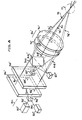
- FIGS. 8 and 9 show alternative embodiments generally similar to that of FIG. 3 but employing more than one radiation source and/or more than one photodetector. Accordingly, components generally similar in construction and function to specific components of the FIG. 3 embodiment will bear the same reference numbers with the addition of a "prime" symbol ('). Where components that are somewhat analogous to components shown in the FIG. 3 embodiment have been replaced with several components, then double prime (' ') and triple prime (' ' '), etc. symbols will also be employed.
- a primary laser source (32') provides the radiation that forms the moving interference fringe planes utilized to make the velocity measurements associated with the velocimeter subsystem.
- the laser (32') should preferably be of a type that may be continuously operated and provides a well-collimated beam of coherent light of a sufficiently short wavelength relative to the diameter of a typical atmospheric aerosol particle that a substantial backscattering will occur as the aerosol particles that naturally occur in the atmosphere pass through the interference fringe planes created in the sample region - (12) by the velocimeter subsystem.
- a second radiation source (32") that functions as the radiation source for the altimeter subsystem.
- the spectral content of the second laser (32' ') should preferably be such as to cause a measurable degree of fluorescence of particular air molecules within the sample region (12) at the altitudes and pressures for which the system will be utilized.
- a dichroic mirror (200) is utilized to combine the- output beam (34') from the first laser (32') with the output beam - (34' ') of the second laser (32' ') to form a combined output beam (34 ' ' ') that is functionally analogous to the output beam (34) of the FIG. 3 embodiment, except that its spectral and coherency characteristics will be a combination of the respective characteristics of the two input beams (34', 34' ').
- Combined beam (34' ' ') is divided into three beams (44', 46', 48') by the beam splitter (36'), these three beams being oriented at approximately 120° intervals about the central axis (50').
- These three beams are then modulated into three diverging beam pairs (64', 66', 68') by the acousto-optic modulator assembly - (38') and are focused by the front element (70') of the window lens (40') into three converging beam pairs (74', 76', 78') that each have their point of intersection centered within the sample region (12) to thereby form interference fringe planes as described previously with reference to the FIG. 3 embodiment.
- the three converging beams - (74', 76', 78') also contain radiant energy originating from the second laser (32'), accordingly, the particular air molecules in the sample region (12) that are sensitive to the radiation (34' ') from the second laser (32' ') will fluoresce.
- a second dichroic mirror (202) separates the received energy (204) into a first component - (206) that has been backscattered from the aerosol molecules and a second component (208) that is associated with the fluorescent re-emissions from individual air molecules with the first component - (206) being directed toward the first photodetector - (42') and the second component being directed to the second photodetector (42' ').
- a single laser radiation source (32) results in two distinct types of received radiation differing substantially in their respective spectral content
- a suitable beam splitter such as dichroic mirror - (202) of the FIG. 8 embodiment
- two individual photodetectors may be employed, each sensitive to only one type of radiation.
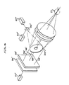
- FIG. 9 shows yet another possible embodiment of the optical components utilized to focus the radiation received from the sample volume (12) onto two photodetectors (42' ' ', 42' ' ' '). It should be noted that this particular embodiment does not employ three separate beam pairs such as were shown in the embodiments of FIGS. 3 and 8 but rather three separate modulated output beams (52', 54', 56') and a single central unmodulated beam - (58').
- Such an alternative form of construction is but one example of a number of different optical arrangements utilizing refracting and/or reflecting optical elements that may be utilized to transmit and focus laser radiation onto a sample volume and to gather and receive the resultant radiation from the sample volume and focus it onto the photodetector or other radiation measurement device.
- an auxiliary focusing element in the optical receiving subsystem namely, a convex reflector (202' ') that is tilted with respect to the central axis of the optics - (50' '), so as to permit the use of two off-axis detectors (42' ' ', 42' ' ' '), with the two radiation components (206', 208') that are focused onto the two photodetectors (42' ' ', 42' ' ' ') being separated by a dichroic mirror (202' ' ').
- the laser velocimeter subsystem and the fluorescent altimeter subsystem may each have utility apart from the other.
- the energy source within the velocimeter subsystem would not need to be switched on and off but could be operated continuously.
- other energy sources could be used in place of the laser within the altimeter subsystem, in particular, fluorescent emissions may be generated in response to radio-frequency electromagnetic radiation (or soft x-rays) directed away from the aircraft skin with the radiant energy preferably being oriented cylindrically about a propagation axis so that it does not significantly fall off in intensity in the vicinity of the sample volume.
- the optical axis of the detector subsystem could cross the radiant energy propagation axis at the sample volume, thereby effectively confining the sample volume to the intersection in three-dimensional space of the detector's effective field of view with the radiant energy beam.
- An optical air data measurement system constructed in accordance with the teachings of the present invention may be utilized in many different types of instrumentation systems, such as provided for use aboard an aircraft, in which case air flight data measurements of variables such as air density, altitude, air speed, angle of attack and side slip angle may be made with enhanced accuracy and reliability.
- the velocimeter subsystem may find separate utility in aircraft instrumentation systems provided with a conventional altimeter.
Landscapes
- Engineering & Computer Science (AREA)
- Physics & Mathematics (AREA)
- General Physics & Mathematics (AREA)
- Health & Medical Sciences (AREA)
- Software Systems (AREA)
- Theoretical Computer Science (AREA)
- Nuclear Medicine, Radiotherapy & Molecular Imaging (AREA)
- Analytical Chemistry (AREA)
- Optics & Photonics (AREA)
- Multimedia (AREA)
- General Engineering & Computer Science (AREA)
- Life Sciences & Earth Sciences (AREA)
- Chemical & Material Sciences (AREA)
- Aviation & Aerospace Engineering (AREA)
- Biochemistry (AREA)
- General Health & Medical Sciences (AREA)
- Immunology (AREA)
- Pathology (AREA)
- Investigating, Analyzing Materials By Fluorescence Or Luminescence (AREA)
- Investigating Or Analysing Materials By Optical Means (AREA)
- Optical Radar Systems And Details Thereof (AREA)
Applications Claiming Priority (6)
| Application Number | Priority Date | Filing Date | Title |
|---|---|---|---|
| US06/328,721 US4506979A (en) | 1981-12-08 | 1981-12-08 | Compact radiation fringe velocimeter for measuring in three dimensions |
| US328721 | 1981-12-08 | ||
| US328476 | 1981-12-08 | ||
| US06/328,476 US4572667A (en) | 1981-12-08 | 1981-12-08 | Fluorescent air data measurement device |
| US06/360,500 US4483614A (en) | 1981-12-08 | 1982-03-22 | Optical air data measurement system |
| US360500 | 1982-03-22 |
Related Parent Applications (2)
| Application Number | Title | Priority Date | Filing Date |
|---|---|---|---|
| EP82306478A Division EP0083162B1 (de) | 1981-12-08 | 1982-12-06 | Optisches Luftdaten Mess-System |
| EP82306478.7 Division | 1982-12-06 |
Publications (2)
| Publication Number | Publication Date |
|---|---|
| EP0227911A2 true EP0227911A2 (de) | 1987-07-08 |
| EP0227911A3 EP0227911A3 (de) | 1988-08-24 |
Family
ID=27406602
Family Applications (2)
| Application Number | Title | Priority Date | Filing Date |
|---|---|---|---|
| EP86115064A Withdrawn EP0227911A3 (de) | 1981-12-08 | 1982-12-06 | Optisches Luftdatenmesssystem |
| EP82306478A Expired EP0083162B1 (de) | 1981-12-08 | 1982-12-06 | Optisches Luftdaten Mess-System |
Family Applications After (1)
| Application Number | Title | Priority Date | Filing Date |
|---|---|---|---|
| EP82306478A Expired EP0083162B1 (de) | 1981-12-08 | 1982-12-06 | Optisches Luftdaten Mess-System |
Country Status (4)
| Country | Link |
|---|---|
| EP (2) | EP0227911A3 (de) |
| JP (1) | JPH01301171A (de) |
| CA (1) | CA1209230A (de) |
| DE (1) | DE3279005D1 (de) |
Cited By (3)
| Publication number | Priority date | Publication date | Assignee | Title |
|---|---|---|---|---|
| EP0446101A1 (de) * | 1990-03-08 | 1991-09-11 | SEXTANT Avionique | Lasersystem zur Messung des Anstellwinkels eines Flugzeugs |
| EP0374822B1 (de) * | 1988-12-22 | 1992-11-25 | Honeywell Inc. | Gepulstes Fluoreszenz-Geschwindigkeitsmessgerät und Verfahren zum Messen der Geschwindigkeit mittels Fluoreszenz |
| GB2284667A (en) * | 1993-12-10 | 1995-06-14 | Sextant Avionique | Optical measurement of the pressure of a gaseous mixture |
Families Citing this family (3)
| Publication number | Priority date | Publication date | Assignee | Title |
|---|---|---|---|---|
| US4887213A (en) * | 1987-07-31 | 1989-12-12 | The Titan Corporation | System for, and methods of, providing for a determination of the movement of an airborne vehicle in the atmosphere |
| GB0304344D0 (en) | 2003-02-26 | 2003-04-02 | Bae Systems Plc | Gas velocity sensor |
| US12068076B1 (en) * | 2020-05-10 | 2024-08-20 | Aleck Alexopoulos | System and method for asthma monitoring and prognosis |
Family Cites Families (6)
| Publication number | Priority date | Publication date | Assignee | Title |
|---|---|---|---|---|
| US3334235A (en) * | 1963-12-19 | 1967-08-01 | Sperry Rand Corp | Photosensitive fluorescent lifetime measuring apparatus |
| US3612859A (en) * | 1968-01-31 | 1971-10-12 | Westinghouse Electric Corp | Method for measuring and controlling the density of a metallic vapor |
| FR2154376B1 (de) * | 1971-09-29 | 1975-07-18 | Sogreah | |
| US4148585A (en) * | 1977-02-11 | 1979-04-10 | The United States Of America As Represented By The Department Of Health, Education & Welfare | Three dimensional laser Doppler velocimeter |
| DE2841499C2 (de) * | 1978-09-23 | 1984-04-12 | Messerschmitt-Bölkow-Blohm GmbH, 8000 München | Laser-Luftwerte-Sensor |
| US4572667A (en) * | 1981-12-08 | 1986-02-25 | Lockheed Corporation | Fluorescent air data measurement device |
-
1982
- 1982-12-06 EP EP86115064A patent/EP0227911A3/de not_active Withdrawn
- 1982-12-06 DE DE8282306478T patent/DE3279005D1/de not_active Expired
- 1982-12-06 EP EP82306478A patent/EP0083162B1/de not_active Expired
- 1982-12-07 CA CA000417139A patent/CA1209230A/en not_active Expired
-
1989
- 1989-04-18 JP JP1098617A patent/JPH01301171A/ja active Pending
Non-Patent Citations (4)
| Title |
|---|
| CHEMICAL PHYSICS LETTERS, vol. 37, no. 2, 15th January 1976, pages 243-248; R.F.HEIDNER III et al.: "Kinetic study of N2(B3IIg,v) quenching by laser-induced fluorescence" * |
| IBM TECHNICAL DISCLOSURE BULLETIN, vol. 8, no. 7, 7th December 1965, page 98, New York, US; K.B.EISENTHAL et al.: "Laser induced luminescence" * |
| LASER & ELEKTRO-OPTIK, vol. 12, no. 3, September 1980, pages 36-39, Stuttgart, DE; U.BRINKMANN et al.: "Diagnostik gasdynamischer Strahlen mit laserinduzierter Fluoreszenz: lokale Geschwindigkeits-, Dichte- und Temperaturprofile" * |
| REVIEW SCIENTIFIC INSTRUMENTS, vol. 50, no. 12, December 1979, pages 1505-1515, American Institute of Physics, New York, US; D.D.DAVIS et al.: "Airborne laser induced fluorescence system for measuring OH and other trace gases in the parts-per-quadrillion to parts-per-trillion range" * |
Cited By (5)
| Publication number | Priority date | Publication date | Assignee | Title |
|---|---|---|---|---|
| EP0374822B1 (de) * | 1988-12-22 | 1992-11-25 | Honeywell Inc. | Gepulstes Fluoreszenz-Geschwindigkeitsmessgerät und Verfahren zum Messen der Geschwindigkeit mittels Fluoreszenz |
| EP0446101A1 (de) * | 1990-03-08 | 1991-09-11 | SEXTANT Avionique | Lasersystem zur Messung des Anstellwinkels eines Flugzeugs |
| FR2659452A1 (fr) * | 1990-03-08 | 1991-09-13 | Sextant Avionique | Systeme a laser, de mesure de l'angle d'incidence d'un aeronef. |
| GB2284667A (en) * | 1993-12-10 | 1995-06-14 | Sextant Avionique | Optical measurement of the pressure of a gaseous mixture |
| GB2284667B (en) * | 1993-12-10 | 1997-12-10 | Sextant Avionique | Method & apparatus for the optical measurement of the pressure of a gaseous mixture |
Also Published As
| Publication number | Publication date |
|---|---|
| JPH01301171A (ja) | 1989-12-05 |
| CA1209230A (en) | 1986-08-05 |
| EP0083162A1 (de) | 1983-07-06 |
| EP0227911A3 (de) | 1988-08-24 |
| EP0083162B1 (de) | 1988-09-07 |
| DE3279005D1 (en) | 1988-10-13 |
Similar Documents
| Publication | Publication Date | Title |
|---|---|---|
| US4483614A (en) | Optical air data measurement system | |
| US4506979A (en) | Compact radiation fringe velocimeter for measuring in three dimensions | |
| US5002389A (en) | Pulsed fluorescence velocimeter | |
| US7106447B2 (en) | Molecular optical air data systems (MOADS) | |
| Durst | Combined measurements of particle velocities, size distributions, and concentrations | |
| JPH0345341B2 (de) | ||
| US5159407A (en) | Single-ended dual spatial filter detector for the passive measurement of winds and turbulence aloft | |
| Bilbro | Atmospheric laser Doppler velocimetry: an overview | |
| US4148585A (en) | Three dimensional laser Doppler velocimeter | |
| Foremen et al. | 8C2-fluid flow measurements with a laser Doppler velocimeter | |
| US3547540A (en) | Laser fluid velocity detector | |
| US5160976A (en) | Optical determination of velocity using crossed interference fringe patterns | |
| US20080297762A1 (en) | System and method for determining crosswinds | |
| US3548655A (en) | Measurement of fluid or surface velocities | |
| US8749794B2 (en) | Optical device for measuring anemometer parameters | |
| US4026655A (en) | Pseudo-backscatter laser doppler velocimeter employing antiparallel-reflector in the forward direction | |
| EP1053453B1 (de) | Verbesserungen bei der detektion von akustischen signalen | |
| US12555484B2 (en) | Systems and methods for diminishing vehicle contrails | |
| HK143394A (en) | Apparatus attached to a moveable device to obtain signals representative of the speed of the device relative to a fluid, and measurement system incorporating such apparatus | |
| US3623361A (en) | Optical probing of supersonic flows with statistical correlation | |
| US3680961A (en) | Measurement of particle sizes | |
| EP0083162B1 (de) | Optisches Luftdaten Mess-System | |
| Seyfried et al. | Continuous monitoring of volcanic eruption dynamics: a review of various techniques and new results from a frequency-modulated radar Doppler system | |
| US4284350A (en) | Laser geophone | |
| EP0374607A1 (de) | Vorrichtung zur Bestimmung der Bewegung eines Flugzeuges in der Atmosphäre |
Legal Events
| Date | Code | Title | Description |
|---|---|---|---|
| PUAI | Public reference made under article 153(3) epc to a published international application that has entered the european phase |
Free format text: ORIGINAL CODE: 0009012 |
|
| AC | Divisional application: reference to earlier application |
Ref document number: 83162 Country of ref document: EP |
|
| AK | Designated contracting states |
Kind code of ref document: A2 Designated state(s): DE FR GB NL |
|
| PUAL | Search report despatched |
Free format text: ORIGINAL CODE: 0009013 |
|
| AK | Designated contracting states |
Kind code of ref document: A3 Designated state(s): DE FR GB NL |
|
| 17P | Request for examination filed |
Effective date: 19881010 |
|
| 17Q | First examination report despatched |
Effective date: 19900523 |
|
| STAA | Information on the status of an ep patent application or granted ep patent |
Free format text: STATUS: THE APPLICATION IS DEEMED TO BE WITHDRAWN |
|
| 18D | Application deemed to be withdrawn |
Effective date: 19901204 |
|
| RIN1 | Information on inventor provided before grant (corrected) |
Inventor name: ROGERS, PHILIP LOUIS |